What is worth exchange Cortex-M3?
 ARM Cortex-M3 is probably the most popular 32-bit processor core for embedded systems today. Microcontrollers on its base produce dozens of manufacturers. The reason for this is a universal, well-balanced architecture, and the result is a continuously growing base of ready-made software and hardware solutions.
In general, there is nothing to blame the Cortex-M3, but today I propose to consider in detail the Cortex-M4F - an extended version of the well-loved processor core. To transfer a project from a microcontroller based on a Cortex-M3 to a crystal based on a Cortex-M4F is quite simple, and for a number of tasks such a transition is worth the effort.
Under the cat a brief overview of modern Cortex, a detailed description of the blocks and commands that distinguish the Cortex-M4F from the Cortex-M3, as well as a comparison of the processor cores on the real problem - we will measure the flicker frequency of the lamp on microcontrollers with different cores.
')
Part of the review
A huge number of articles and reviews have been written about how each generation of the ARM processor cores succeeded each other. I see no reason to paint everything that is in Wikipedia, but I recall the basic facts.
ARM Ltd. develops microprocessor and microcontroller cores with a RISC architecture and sells licenses for the manufacture of crystals using appropriate technology to electronic component manufacturers. There are dozens and even hundreds of such manufacturers all over the world, there are domestic companies among them.
Modern ARM cores are united by the name Cortex.
By the way, the word “cortex” is translated as “cerebral cortex” - a structure responsible for coordinated work of organs, thinking, and higher nervous activity. In my opinion, a great name.
So, ARM Cortex processor cores are divided into three main groups:
- Cortex-A - Application Processors - for applications requiring high performance; most often, they run linux, android and the like.
- Cortex-R - Embedded Real-time Processors - for real-time applications
- Cortex-M - Embedded Processors - for embedded systems
Consider the last group, gradually approaching the Cortex-M3 / Cortex-M4F pair. In total, at the end of 2015, six processor cores were presented: Cortex-M0, -M0 +, -M1, -M3, -M4, -M7.
The Cortex-M1 often falls out of this list, this is because -M1 is designed and used exclusively in FPGA-related applications. The remaining cores do not have such a specialized application and differ in performance - from the simplest -M0 to high-performance -M7.

Compared to Cortex-M0, Cortex-M0 + is additionally equipped with an MPU memory protection unit, Micro Trace Buffer for debugging programs, and also has a two-stage conveyor instead of three-step and simplified access to peripheral units and I / O lines.
Cortex-M0 and Cortex-M0 + have a single-Von-Neumann architecture, and the core Cortex-M3 is already Harvard. Cortex-M3 is quite different from the "younger" representatives of the line and has much more opportunities.
Cortex-M4 is built according to absolutely the same architecture and “structurally” does not differ from the Cortex-M3. The difference is in the supported command system, but more on that later. Cortex-M4F differs from -M4 in the presence of the FPU floating point unit.
The Cortex-M7 architecture is relatively new and differs from the Cortex-M3 / M4 as much as the Cortex-M3 / M4 differs from the Cortex-M0. The 6-step superscalar pipeline, a separate cache for data and commands, a configurable TCM memory, and other distinctive features of this core are “sharpened” for maximum performance. Indeed, the capabilities of the Cortex-M7 based controllers are compared with the Cortex-A5 and -R5, rather than with other controllers of the Embedded Processors group. The boundaries of technology continue to blur.
Despite the completely different capabilities of the cores of the Cortex-M group, the instruction set of each core includes all the commands supported in the younger cores. This ensures the possibility of developing software-compatible microcontrollers based on different cores, and this is what most manufacturers of microcontrollers are doing.

The Cortex-M0 and Cortex-M0 + kernels have the same instruction set. The Cortex-M3 instruction set includes all the Cortex-M0 commands and about a hundred additional instructions. The Cortex-M4 and Cortex-M7 processor cores have, again, an identical instruction set — the Cortex-M3 instruction set plus the so-called DSP instructions. The Cortex-M4F core, in addition to the Cortex-M4 / M7 set, supports floating-point commands, and the Cortex-M7F command system includes 14 more commands for double-precision floating-point operations.
Part theoretical
So, the closest "neighbors" of the popular Cortex-M3 processor core are Cortex-M4, supplemented by support for DSP instructions, and Cortex-M4F, additionally containing an FPU and supporting the appropriate commands. Consider the DSP and FPU commands.
DSP instructions
The DSP abbreviation is often stands for Digital Signal Processor, i.e. A separate and completely independent controller or coprocessor designed for the tasks of digital signal processing. Do not confuse a specialized DSP chip and a set of DSP instructions. DSP commands (decrypted by Digital Signal Process ing instead of Process or ) is a set of commands that is supported by a number of ARM processor cores and corresponds to some typical operations for digital signal processing.
The first group of such operations is Single-cycle Multiply Accumulate or simply MAC.
For the smallest ones: multiplication with accumulation is described by the formula S = S + A x B. The corresponding commands describe multiplication of two registers with summation of the result into the accumulator and related operations: multiplication with subtraction of the result from the accumulator, multiplication without using the accumulator, etc.
Operations are provided for 16- and 32-bit variables and play an important role in many typical digital signal processing algorithms. For example, an FIR filter (this is a classic, almost banal “for example”) is a sequence of multiplication with accumulation, which means its speed directly depends on the speed of multiplication with accumulation.
All MAC instructions in microcontrollers with a Cortex-M4 (F) core are executed in one machine cycle.
The second group of DSP instructions is parallel data processing operations (Single Instruction Multiple Data, SIMD), which allow optimizing data processing due to parallelism of calculations. Pairs of independent variables are placed in pairs in one register of a higher dimension, and arithmetic operations are already performed on “large” registers.
For example, the SADD16 command implies the simultaneous addition of two pairs of 16-bit signed numbers with the result written to the register storing the first operand.
SADD16 R1, R0 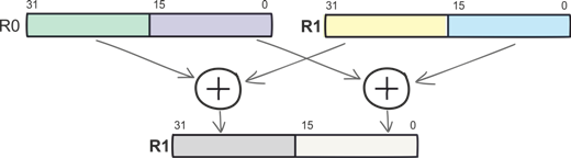
Since general-purpose registers are 32 bits wide, not only two 16-bit variables (half words) can be written to each of them, but also up to four 8-bit variables (bytes). Now it's easy to figure out why you need the SADD8 command.
Here is a more complicated operation: multiplication of the older half words, multiplication of the lower half words, and summation of works among themselves and with 64-bit accumulation. The SMLALD team describes all these actions and performs Cortex-M4 in one machine cycle. SMLALD, like many other commands, combines multiplication with the accumulation and processing of data on the principle of SIMD.
SMLALD R6, R8, R5, R1 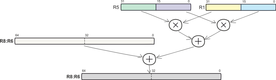
Both simple SIMD commands (signed and unsigned 8- and 16-bit addition and subtraction, etc.), and complex instructions like SMLALD are executed in one machine cycle.
The next group of DSP instructions is the Saturating instructions. They are also known as cut-off operations and provide protection against overflows. When using standard commands, the register storing the result, when overflowed, “reboots” from scratch, and commands providing saturation, when overflowing, fix the result at the maximum allowed by the digit capacity. Thus, the programmer eliminates the need to take care of overflow flags.
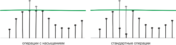
Among the commands of the Cortex-M4 processor core there are both “ordinary” arithmetic operations and the same operations with saturation. The use of the latter is especially in demand in tasks where the accuracy of calculations can be sacrificed for the sake of speed. There are a lot of such tasks in DSP.
FPU instructions
Hardware support for floating-point calculations (or a dot, whichever you like) is a feature of the Cortex-M4F core and more senior Cortex-M members.
Commands for floating-point calculations allow you to perform operations on real numbers with maximum performance. In general, today two numbers are used to represent real numbers - fixed and floating point. In the first case, the number of digits for recording the whole and fractional parts is fixed and the calculations are reduced to operations on integers; in the second, the number is represented as a set of a sign bit, several order bits and a mantissa:
(-1) s * m × b e ,
where s is the sign, b-base, e is the order, and m is the mantissa
Using floating point format is preferable when processing signals due to a much wider range of float variable values. Using FPU operations also saves the developer from having to keep track of the bit depth. The single-precision floating-point format is described by the IEEE 754 standard, this representation is used in microcontrollers with the Cortex-M4F core. The range of acceptable values is (10 –38 ... 10 38 ) with approximate conversion to decimal numbers.

By the way, for the double-precision floating-point format, which is supported in the Cortex-M7F, the same principle is used, but instead of the 32-bit representation, 64-bit is used, i.e. the order is 11 bits, and the mantissa is 52.
About how and why the floating-point format is used more than once is written on Habré (for example, an excellent article). I, perhaps, do not write better, so go ahead.
List of assembler DSP and FPU commands
To get a feel for the scale — understand how much data processing can be accelerated using Cortex-M4 — you can study the full list of DSP and FPU instructions. I have big doubts about the practical value of these tables, it’s interesting to see.
All DSP and most FPU instructions are executed in one machine cycle.
Cortex-M4 core DSP instructions
| Team | Operation |
| PKHTB, PKHBT | rewriting the half-word from one register to another, if necessary, shifting the contents of the "receiving" register |
| QADD | sign addition with saturation |
| QADD16 | sign addition of the corresponding half-words of two operands (with saturation) |
| QADD8 | sign addition of the corresponding bytes of two operands (with saturation) |
| QASX | the sign addition of the younger half-word of the second operand and the higher half-word of the first operand, the sign subtraction of the higher half-word of the second operand from the younger half-word of the first operand (with saturation) |
| QDADD | doubling the second operand, summing the result with the first operand (signed, with saturation) |
| QDSUB | doubling the second operand, subtracting the result from the first operand (signed, with saturation) |
| QSAX | signed subtraction of the lower half-word of the second operand from the higher half-word of the first operand + sign addition of the lower half-word of the first operand and higher half-word of the second operand (with saturation) |
| QSUB | sign subtraction (with saturation) |
| QSUB16 | sign subtraction of the corresponding half words of two operands (with saturation) |
| QSUB8 | signed subtraction of the corresponding bytes of two operands (with saturation) |
| SADD16 | sign addition of the corresponding half words of two operands |
| SADD8 | sign addition of the corresponding bytes of two operands |
| SASX | the sign addition of the upper half word of the first transpend and the lower half word of the second operand with the entry in the upper half word of the result, the sign subtraction of the lower half word of the second operand from the higher half word of the first half word with a record in the younger half word of the result |
| SEL | selection of bytes from operands in accordance with GE [3: 0] bits ("flags" set when various conditions of the "greater or equal" type are met when performing arithmetic operations) |
| SHADD16 | sign addition of the corresponding half-words of operands, shift of two results by one bit to the right |
| SHADD8 | the sign addition of the corresponding byte operands, the shift of the four results by one bit to the right |
| SHASX | sign addition of the high half word of the first operand and the lower half word of the second operand, writing the result to the upper half word of the specified register with a right shift by one bit, sign subtraction of the high half word of the second operand from the lower half word of the first operand, writing result to the lower half word of the specified register with right shift by one bit |
| SHSAX | sign subtraction of the lower half word of the second operand from the high half word of the first operand, writing the result to the lower half word of the specified register with a shift to the right by one bit, sign addition of the high half word of the second operand and the lower half word of the first operand, writing the result to the senior half word of the specified register with right shift by one bit |
| SHSUB16 | signed subtraction of the high and low half words of the second operand from the corresponding half words of the first operand, shift the result by a bit to the right |
| SHSUB8 | signed subtraction of the high and low bytes of the second operand from the corresponding bytes of the first operand, shift the result by a bit to the right |
| SMLABB, SMLABT, SMLATB, SMLATT | multiplying the upper or lower half words of two operands with 32-bit accumulation |
| SMLAD, SMLADX | pairwise multiplication of the half-words of two operands, summing two products with 32-bit accumulation |
| SMLALBB, SMLALBT, SMLALTB, SMLALTT | multiplication of the sign half-words of two operands (major or minor) with 64-bit accumulation and 64-bit result |
| SMLALD, SMLALDX | pairwise multiplication of two bytes taken from the first operand by two bytes from the second operand, the summation of the two products obtained with 64-bit accumulation and 64-bit result |
| SMLAWB, SMLAWT | multiplying the upper or lower half-word of the first operand by the second operand with 32-bit accumulation, the first 32 bits of the 48-bit result are written into the resulting register |
| SMLSD | subtracting the product of the higher half words of two operands from the lower half words of two operands with 32-bit accumulation |
| SMLSLD | subtracting the product of the higher half words of two operands from the lower half words of two operands with 64-bit accumulation |
| SMMLA | multiplying two operands with 32-bit accumulation (only 32 high-order digits are taken) |
| SMMLS, SMMLR | multiplying two operands, subtracting the result from the specified register (only 32 senior bits of the product are taken) |
| SMMUL, SMMULR | multiplication of operands (the result is the highest 32-bit product) |
| SMUAD | multiplication of the higher half words of two operands, multiplication of the lower half words of two operands, addition of products |
| SMULBB, SMULBT SMULTB, SMULTT | multiplication of the upper or lower half words of two opernds |
| SMULWB, SMULWT | multiplying the first operand by the upper or lower half word of the second operand; the first 32 bits of the 48-bit result are written to the resulting register |
| SMUSD, SMUSDX | multiplication of the higher half words of two operands, multiplication of the lower half words of two operands, subtraction of the first product from the second |
| SSAT16 | sign saturation of half words to the specified value |
| SSAX | significant subtraction of the lower half-word of the second operand from the higher half-word of the first operand with the entry in the lower half-word of the result, the addition of the higher half-word of the first operand and the younger half-word of the second operand with a record in the high-half word |
| SSUB16 | sign subtraction of the corresponding half words of two operands |
| SSUB8 | signed subtraction of the corresponding bytes of the two operands |
| SXTAB | extracting bits [7: 0] from the register and converting them into a 32-bit word, taking into account the sign, adding the result with the word or half-word |
| SXTAB16 | extracting bits [7: 0] and [23:16] from the register, converting them to half-words, taking into account the sign, adding the result to a word or half-word |
| SXTAH | extracting bits [15: 0] from the register and converting them into a 32-bit word, taking into account the sign, adding the result with the word or half-word |
| SXTB16 | conversion of two bytes to two half words, taking into account the sign, the addition of the result with a word or a half-word |
| UADD16 | unsigned addition of the corresponding half words of two operands |
| UADD8 | unsigned addition of the corresponding bytes of two operands |
| USAX | addition of the lower half-word of the first operand and the higher half-word of the second operand with recording the result in the lower half-word of the result, unsigned subtraction of the lower half-word of the second operand from the higher half-word of the first operand with a record in the older half-word of the result |
| UHADD16 | unsigned addition of the corresponding half words of the two operands and shift the results by one bit to the right |
| UHADD8 | unsigned addition of the corresponding bytes of the two operands and shift the results by one bit to the right |
| Uhasx | unsigned addition of the upper half-word of the first operand and the lower half-word of the second operand with a shift of the result of addition by one bit to the right and writing to the higher half-word of the result, unsigned subtraction of the higher half-word of the second operand from the younger half-word of the first operand with shift of the result of subtraction by one bit to the right and writing to the younger half-word result |
| UHSAX | unsigned subtraction of the second half-word of the second operand from the upper half-word of the first operand with a shift of the subtraction result by one bit to the right and writing to the upper half-word of the result, unsigned addition of the younger half-word of the first operand and the higher half-word of the second operand with a shift of the addition result by one bit to the right and writing to the younger half-word result, |
| UHSUB16 | unsigned subtraction of the corresponding half words of two operands, shifting the result one bit to the right |
| UHSUB8 | unsigned subtraction of the corresponding bytes of the two operands, shift the result one bit to the right |
| Umaal | unsigned multiplication with double 32-bit accumulation and 64-bit result |
| UQADD16 | unsigned addition of 16-bit variables (with saturation) |
| UQADD8 | unsigned addition of 8-bit variables (with saturation) |
| Uqasx | unsigned subtraction of the lower half-word of the second operand from the higher half-word of the first operand, unsigned addition of the younger half-word of the first operand and the higher half-word of the second operand (with saturation) |
| UQSAX | unsigned subtraction of the lower half-word of the second operand from the higher half-word of the first operand, unsigned addition of the younger half-word of the first operand and the higher half-word of the second operand (with saturation) |
| UQSUB16 | unsigned subtraction of the corresponding half words of two operands (with saturation) |
| UQSUB8 | unsigned subtraction of the corresponding bytes of two operands (with saturation) |
| USAD8 | unsigned subtraction of the corresponding bytes of the two operands, the addition of absolute differences |
| USADA8 | unsigned subtraction of the corresponding bytes of the two operands, the addition of absolute differences, the addition of the result of the operation with the contents of the battery |
| USAT16 | unsigned saturation of half words to the specified value |
| Uasx | unsigned subtraction of the higher half-word of the second operand from the lower half-word of the first operand with the entry in the lower half-word of the result, the addition of the higher half-word of the first operand and the younger half-word of the second operand with a record of the result in the higher half-word result |
| USUB16 | unsigned subtraction of the corresponding half words of two operands |
| USUB8 | unsigned subtraction of the corresponding bytes of the two operands |
| UXTAB | extracting bits [7: 0] from the register and converting them into a 32-bit word without a sign, adding the result with a word or a half-word |
| UXTAB16 | extracting bits [7: 0] and [23:16] from the register, converting them to half-words without taking into account the sign, adding the result to a word or half-word |
| Uxtah | extract bits [15: 0] from the register and convert them to a 32-bit word without a sign, adding the result to a word or a half-word |
| UXTB16 | conversion of two bytes to two half-words without a sign, adding the result with a word or a half-word |
Cortex-M4F FPU kernel instructions
| Team | Operation |
| VABS.F32 | obtaining the absolute value of the operand |
| VADD.F32 | addition of operands |
| VCMP.F32 | comparing two operands or operand and zero |
| VCMPE.F32 | comparison of two operands or operand and zero with checking for an incorrect operand (NaN) |
| VCVT.S32.F32 | conversion between data types (float / integer) |
| VCVT.S16.F32 | conversion between data types (floating point / fixed point) |
| VCVTR.S32.F32 | conversion between data types (float / integer) with rounding |
| VCVT <B | H> .F32.F16 | conversion between data types (floating point half-word - it's also a half-precision number / floating-point) |
| VCVTT <B | T> .F32.F16 | conversion between data types (floating point / floating point half-word) |
| VDIV.F32 | division of operands |
| VFMA.F32 | multiplication of two variables, adding the result of multiplication to the contents of the specified register |
| VFNMA.F32 | Invert the first sample, multiply the result by the second operand, add the product and the inverted value from the specified register |
| VFMS.F32 | Invert the first sample, multiply the result by the second operand, add the product and the value from the specified register |
| VFNMS.F32 | multiplying two operands, adding the product and the inverted value from the specified register |
| VLDM.F <32 | 64> | extracting the contents of several specified registers from program memory |
| VLDR.F <32 | 64> | extracting the contents of the specified register from the program memory |
| VLMA.F32 | multiplication with accumulation |
| VLMS.F32 | subtracting the product of two operands from the specified register |
| VMOV | transferring data between "standard" ARM registers and FPSCR registers (Floating-Point Status and Control Register), transferring data between registers storing floating-point format (FPU registers), writing constants to FPU registers, etc. |
| VMOV, VMRS, VMSR | data transfer between the “standard” ARM registers and the FPSCR (Floating-Point Status and Control Register) registers |
| VMUL.F32 | multiplication of operands |
| VNEG.F32 | inversion |
| VNMLA.F32 | multiplication of two operands, result inventing, addition of the inverted product and the inverted value from the specified register |
| VNMLS.F32 | multiplication of two operands, product and inverted value from the specified register |
| VNMUL | multiplication of two operands, result inventing |
| VPOP | pop |
| VPUSH | push |
| VSQRT.F32 | square root |
| VSTM | saving the contents of several specified registers to the program memory |
| VSTR.F <32 | 64> | saving the contents of the specified register to the program memory |
| VSUB.F <32 | 64> | subtraction of operands |
However, in practice, the kernel instructions themselves are not often used. Usually during development it is enough to deal with the documentation for the controller and the libraries from the core and chip manufacturers. In particular, for the Cortex cores, there is an ARM CMSIS library set, which is used for Cortex-M processors from different manufacturers. CMSIS also includes the CMSIS-DSP library, it includes:
- basic math functions, vector operations
- fast trigonometric and transcendental functions (sin, cos, sqrt, etc.)
- linear and bilinear interpolations
- complex arithmetic
- statistical functions
- filtering algorithms - IIR, FIR filters, minimal mean square error algorithm
- signal conversion algorithms (FFT, etc.)
- matrix arithmetic
- PID controller
- array functions
Part practical
As a rule, the comparison of the Cortex-M3 and Cortex-M4 (F) cores ends with beautiful graphs - histograms that show a significant acceleration of the operation of the Cortex-M4 based controller when performing typical DSP operations (FIR filter, FFT, matrix calculations, FID -regulator, etc.). Without instructions of the used controllers, a technique of calculations and measurements.
But we will not compare Tide and Regular laundry detergent; instead, we will take a real hardware and software platform.
At this point, it makes sense to digress and think a little about the problems for which the mathematical apparatus Cortex-M4F is relevant. It is clear that the work with streaming data and multimedia performance of the Cortex-M4 core is not enough, we are talking more about control systems and data processing.
For example, some telemetry data is being collected. , , «» . — , .
. - -. bluetooth ? Of course not. .
. , « »? ! , .
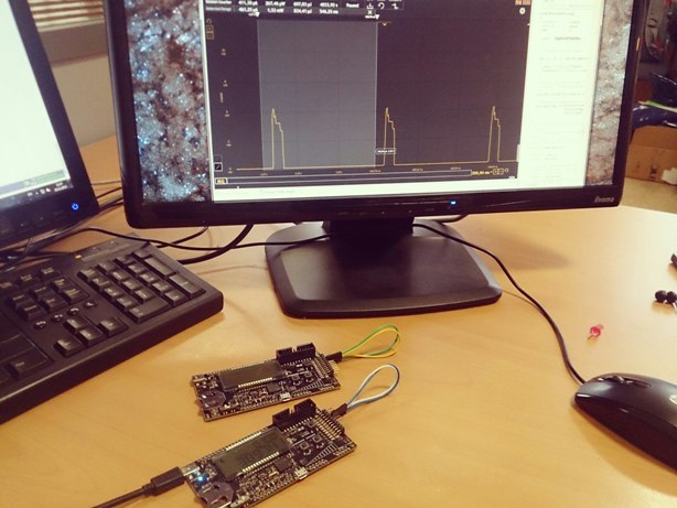
EFM32 Wonder Gecko SiLabs. . -.
EFM32WG — Cortex-M4F. EFM32, . Cortex-M3 Cortex-M4F.
:
EFM32WG-STK3800 — Cortex-M4F
EFM32GG-STK3700 — Cortex-M3
.

Simplicity Studio. SiLabs- , , , , Silabs. — IDE, energy profiler, user guide .
The essence of the experiment
. , , , 0,5 : 512 . ProcessFFT().
, . .
Simplicity Studio, Simplicity IDE, .
, — , Simplicity IDE, IAR, Keil .
/***************************************************************************//** * @file lightsensefft.c * @brief FFT transform example * @details * Use ADC in order to capture and analyse input from the * light sensor on the STK. Runs floating point FFT algorithm from the CMSIS * DSP Library, and estimate the frequency of the most luminous light source * using sinc interpolation. The main point with this example is to show the * use of the CMSIS DSP library and the floating point capability of the CPU. * * @par Usage * Connect the light sensor output to the ADC input by shorting pins * 15 and 14 on the EXP_HEADER of the STK. * Direct various light sources to the light sensor. Expect no specific * frequency from daylight or from a flashlight. Mains powered incandescent * bulbs should give twice the mains frequency. Using another STK running the * "blink" example modified to various blink rates is an excellent signal * source. The frequency bandwidth is approximately 10-500 Hz. * The frequency shows in the 4 digit numerical display upper right on * the LCD. The LCD also displays the number of CPU cycles used to do * the FFT transform. * * @author Silicon Labs * @version 1.04 ******************************************************************************* * @section License * <b>(C) Copyright 2014 Silicon Labs, http://www.silabs.com</b> ******************************************************************************* * * Permission is granted to anyone to use this software for any purpose, * including commercial applications, and to alter it and redistribute it * freely, subject to the following restrictions: * * 1. The origin of this software must not be misrepresented; you must not * claim that you wrote the original software. * 2. Altered source versions must be plainly marked as such, and must not be * misrepresented as being the original software. * 3. This notice may not be removed or altered from any source distribution. * * DISCLAIMER OF WARRANTY/LIMITATION OF REMEDIES: Silicon Labs has no * obligation to support this Software. Silicon Labs is providing the * Software "AS IS", with no express or implied warranties of any kind, * including, but not limited to, any implied warranties of merchantability * or fitness for any particular purpose or warranties against infringement * of any proprietary rights of a third party. * * Silicon Labs will not be liable for any consequential, incidental, or * special damages, or any other relief, or for any claim by any third party, * arising from your use of this Software. * ******************************************************************************/ #include "em_common.h" #include "em_emu.h" #include "em_cmu.h" #include "em_chip.h" #include "em_adc.h" #include "em_gpio.h" #include "em_rtc.h" #include "em_acmp.h" #include "em_lesense.h" #include "segmentlcd.h" #include "arm_math.h" #include "math.h" /** * Number of samples processed at a time. This number has to be equal to one * of the accepted input sizes of the rfft transform of the CMSIS DSP library. * Increasing it gives better resolution in the frequency, but also a longer * sampling time. */ #define BUFFER_SAMPLES 512 /** (Approximate) sample rate used for sampling data. */ #define SAMPLE_RATE (1024) /** The GPIO pin used to power the light sensor. */ #define EXCITE_PIN gpioPortD,6 /* Default configuration for alternate excitation channel. */ #define LESENSE_LIGHTSENSE_ALTEX_DIS_CH_CONF \ { \ false, /* Alternate excitation enabled.*/ \ lesenseAltExPinIdleDis, /* Alternate excitation pin is disabled in idle. */ \ false /* Excite only for corresponding channel. */ \ } /* ACMP */ #define ACMP_NEG_REF acmpChannelVDD #define ACMP_THRESHOLD 0x38 /* Reference value for the lightsensor. * Value works well in office light * conditions. Might need adjustment * for other conditions. */ /* LESENSE Pin config */ #define LIGHTSENSE_CH 6 #define LIGHTSENSE_EXCITE_PORT gpioPortD #define LIGHTSENSE_EXCITE_PIN 6 #define LIGHTSENSE_SENSOR_PORT gpioPortC #define LIGHTSENSE_SENSOR_PIN 6 #define LCSENSE_SCAN_FREQ 5 #define LIGHTSENSE_INTERRUPT LESENSE_IF_CH6 /** Buffer of uint16_t sample values ready to be FFT-ed. */ static uint16_t lightToFFTBuffer[BUFFER_SAMPLES]; /** Buffer of float samples ready for FFT. */ static float32_t floatBuf[BUFFER_SAMPLES]; /** Complex (interleaved) output from FFT. */ static float32_t fftOutputComplex[BUFFER_SAMPLES * 2]; /** Magnitude of complex numbers in FFT output. */ static float32_t fftOutputMag[BUFFER_SAMPLES]; /** Flag used to indicate whether data is ready for processing */ static volatile bool dataReadyForFFT; /** Indicate whether we are currently processing data through FFT */ static volatile bool processingFFT; /** Instance structures for float32_t RFFT */ static arm_rfft_instance_f32 rfft_instance; /** Instance structure for float32_t CFFT used by the RFFT */ static arm_cfft_radix4_instance_f32 cfft_instance; /**************************************************************************//** * Interrupt handlers prototypes *****************************************************************************/ void LESENSE_IRQHandler(void); /**************************************************************************//** * Functions prototypes *****************************************************************************/ void setupCMU(void); void setupACMP(void); void setupLESENSE(void); /**************************************************************************//** * @brief LESENSE_IRQHandler * Interrupt Service Routine for LESENSE Interrupt Line *****************************************************************************/ void LESENSE_IRQHandler(void) { /* Clear interrupt flag */ LESENSE_IntClear(LIGHTSENSE_INTERRUPT); } /***************************************************************************//** * @brief Enables LFACLK and selects osc as clock source for RTC ******************************************************************************/ void RTC_Setup(CMU_Select_TypeDef osc) { RTC_Init_TypeDef init; /* Ensure LE modules are accessible */ CMU_ClockEnable(cmuClock_CORELE, true); /* Enable osc as LFACLK in CMU (will also enable oscillator if not enabled) */ CMU_ClockSelectSet(cmuClock_LFA, osc); /* Division prescaler to decrease consumption. */ CMU_ClockDivSet(cmuClock_RTC, cmuClkDiv_32); /* Enable clock to RTC module */ CMU_ClockEnable(cmuClock_RTC, true); init.enable = false; init.debugRun = false; init.comp0Top = true; /* Count only to top before wrapping */ RTC_Init(&init); /* RTC clock divider is 32 which gives 1024 ticks per second. */ RTC_CompareSet(0, ((1024 * SAMPLE_RATE) / 1000000)-1); /* Enable interrupt generation from RTC0, needed for WFE (wait for event). */ /* Notice that enabling the interrupt in the NVIC is not needed. */ RTC_IntEnable(RTC_IF_COMP0); } /**************************************************************************//** * @brief Enable clocks for all the peripherals to be used *****************************************************************************/ void setupCMU(void) { /* Ensure core frequency has been updated */ SystemCoreClockUpdate(); /* Set the clock frequency to 11MHz so the ADC can run on the undivided HFCLK */ CMU_HFRCOBandSet(cmuHFRCOBand_11MHz); /* ACMP */ CMU_ClockEnable(cmuClock_ACMP0, true); /* GPIO */ CMU_ClockEnable(cmuClock_GPIO, true); /* ADC */ CMU_ClockEnable(cmuClock_ADC0, true); /* Low energy peripherals * LESENSE * LFRCO clock must be enables prior to enabling * clock for the low energy peripherals */ CMU_ClockSelectSet(cmuClock_LFA, cmuSelect_LFRCO); CMU_ClockEnable(cmuClock_CORELE, true); CMU_ClockEnable(cmuClock_LESENSE, true); /* RTC */ CMU_ClockEnable(cmuClock_RTC, true); /* Disable clock source for LFB clock. */ CMU_ClockSelectSet(cmuClock_LFB, cmuSelect_Disabled); } /**************************************************************************//** * @brief Sets up the ACMP *****************************************************************************/ void setupACMP(void) { /* Configuration structure for ACMP */ static const ACMP_Init_TypeDef acmpInit = { .fullBias = false, /* The lightsensor is slow acting, */ .halfBias = true, /* comparator bias current can be set to lowest setting.*/ .biasProg = 0x0, /* Analog comparator will still be fast enough */ .interruptOnFallingEdge = false, /* No comparator interrupt, lesense will issue interrupts. */ .interruptOnRisingEdge = false, .warmTime = acmpWarmTime512, /* Not applicable, lesense controls this. */ .hysteresisLevel = acmpHysteresisLevel5, /* Some hysteresis will prevent excessive toggling. */ .inactiveValue = false, /* Not applicable, lesense controls this. */ .lowPowerReferenceEnabled = false, /* Can be enabled for even lower power. */ .vddLevel = 0x00, /* Not applicable, lesense controls this through .acmpThres value. */ .enable = false /* Not applicable, lesense controls this. */ }; /* Initialize ACMP */ ACMP_Init(ACMP0, &acmpInit); /* Disable ACMP0 out to a pin. */ ACMP_GPIOSetup(ACMP0, 0, false, false); /* Set up ACMP negSel to VDD, posSel is controlled by LESENSE. */ ACMP_ChannelSet(ACMP0, acmpChannelVDD, acmpChannel0); /* LESENSE controls ACMP thus ACMP_Enable(ACMP0) should NOT be called in order * to ensure lower current consumption. */ } /**************************************************************************//** * @brief Sets up the LESENSE *****************************************************************************/ void setupLESENSE(void) { /* LESENSE configuration structure */ static const LESENSE_Init_TypeDef initLesense = { .coreCtrl = { /* LESENSE configured for periodic scan. */ .scanStart = lesenseScanStartPeriodic, .prsSel = lesensePRSCh0, .scanConfSel = lesenseScanConfDirMap, .invACMP0 = false, .invACMP1 = false, .dualSample = false, .storeScanRes = false, .bufOverWr = true, .bufTrigLevel = lesenseBufTrigHalf, .wakeupOnDMA = lesenseDMAWakeUpDisable, .biasMode = lesenseBiasModeDutyCycle, /* Lesense should duty cycle comparator and related references etc. */ .debugRun = false }, .timeCtrl = { .startDelay = 0 /* No start delay needed for this application. */ }, .perCtrl = { /* DAC is not needed for this application. */ .dacCh0Data = lesenseDACIfData, .dacCh0ConvMode = lesenseDACConvModeDisable, .dacCh0OutMode = lesenseDACOutModeDisable, .dacCh1Data = lesenseDACIfData, .dacCh1ConvMode = lesenseDACConvModeDisable, .dacCh1OutMode = lesenseDACOutModeDisable, .dacPresc = 0, .dacRef = lesenseDACRefBandGap, .acmp0Mode = lesenseACMPModeMuxThres, /* Allow LESENSE to control ACMP mux and reference threshold. */ .acmp1Mode = lesenseACMPModeMuxThres, .warmupMode = lesenseWarmupModeNormal /* Normal mode means LESENSE is allowed to dutycycle comparator and reference. */ }, .decCtrl = { /* Decoder or statemachine not used in this code example. */ .decInput = lesenseDecInputSensorSt, .initState = 0, .chkState = false, .intMap = true, .hystPRS0 = false, .hystPRS1 = false, .hystPRS2 = false, .hystIRQ = false, .prsCount = true, .prsChSel0 = lesensePRSCh0, .prsChSel1 = lesensePRSCh1, .prsChSel2 = lesensePRSCh2, .prsChSel3 = lesensePRSCh3 } }; /* Channel configuration */ /* Only one channel is configured for the lightsense application. */ static const LESENSE_ChDesc_TypeDef initLesenseCh = { .enaScanCh = true, .enaPin = false, /* Pin is input, no enabling needed. Separate pin is exciting the sensor. */ .enaInt = true, /* Enable interrupt for this channel. */ .chPinExMode = lesenseChPinExHigh, /* Excite by pullin pin high. */ .chPinIdleMode = lesenseChPinIdleDis, /* During Idle, excite pin should be disabled (tri-stated). */ .useAltEx = true, /* Use alternate excite pin. */ .shiftRes = false, /* Not applicable, only for decoder operation. */ .invRes = false, /* No need to invert result. */ .storeCntRes = true, /* Not applicable, don't care really. */ .exClk = lesenseClkLF, /* Using low frequency clock for timing the excitation. */ .sampleClk = lesenseClkLF, /* Using low frequency clock for timing the sample instant. */ .exTime = 0x01, /* 1 LFclk cycle is enough excitation time, this depends on response time of light sensor. */ .sampleDelay = 0x01, /* Sampling should happen when excitation ends, it it happens earlier, excitation time might as well be reduced. */ .measDelay = 0x00, /* Not used here, basically only used for applications which uses the counting feature. */ .acmpThres = ACMP_THRESHOLD, /* This is the analog comparator threshold setting, determines when the acmp triggers. */ .sampleMode = lesenseSampleModeACMP, /* Sampling acmp, not counting. */ .intMode = lesenseSetIntLevel, /* Interrupt when voltage goes above threshold. */ .cntThres = 0x0000, /* Not applicable. */ .compMode = lesenseCompModeLess /* Not applicable. */ }; /* Alternate excitation channels configuration. */ /* The lightsensor is excited by alternate excite channel 0. */ static const LESENSE_ConfAltEx_TypeDef initAltEx = { .altExMap = lesenseAltExMapALTEX, .AltEx[0] = { .enablePin = true, .idleConf = lesenseAltExPinIdleDis, .alwaysEx = true }, .AltEx[1] = LESENSE_LIGHTSENSE_ALTEX_DIS_CH_CONF, .AltEx[2] = LESENSE_LIGHTSENSE_ALTEX_DIS_CH_CONF, .AltEx[3] = LESENSE_LIGHTSENSE_ALTEX_DIS_CH_CONF, .AltEx[4] = LESENSE_LIGHTSENSE_ALTEX_DIS_CH_CONF, .AltEx[5] = LESENSE_LIGHTSENSE_ALTEX_DIS_CH_CONF, .AltEx[6] = LESENSE_LIGHTSENSE_ALTEX_DIS_CH_CONF, .AltEx[7] = LESENSE_LIGHTSENSE_ALTEX_DIS_CH_CONF }; /* Initialize LESENSE interface _with_ RESET. */ LESENSE_Init(&initLesense, true); /* Configure LESENSE channel */ LESENSE_ChannelConfig(&initLesenseCh, LIGHTSENSE_CH); /* Configure alternate excitation channels */ LESENSE_AltExConfig(&initAltEx); /* Set scan frequency */ LESENSE_ScanFreqSet(0, LCSENSE_SCAN_FREQ); /* Set clock divisor for LF clock. */ LESENSE_ClkDivSet(lesenseClkLF, lesenseClkDiv_2); } /**************************************************************************//** * @brief Sets up the GPIO *****************************************************************************/ void setupGPIO(void) { /* Configure the drive strength of the ports for the light sensor. */ GPIO_DriveModeSet(LIGHTSENSE_EXCITE_PORT, gpioDriveModeStandard); GPIO_DriveModeSet(LIGHTSENSE_SENSOR_PORT, gpioDriveModeStandard); /* Initialize the 2 GPIO pins of the light sensor setup. */ GPIO_PinModeSet(LIGHTSENSE_EXCITE_PORT, LIGHTSENSE_EXCITE_PIN, gpioModePushPull, 0); GPIO_PinModeSet(LIGHTSENSE_SENSOR_PORT, LIGHTSENSE_SENSOR_PIN, gpioModeDisabled, 0); } /**************************************************************************//** * @brief Configure ADC for 12 bit mode, sample channel 0 with Vdd as reference * and use shortest acquisition time. *****************************************************************************/ static void ADC_Config(void) { CMU_ClockEnable(cmuClock_ADC0, true); ADC_Init_TypeDef init = ADC_INIT_DEFAULT; ADC_InitSingle_TypeDef singleInit = ADC_INITSINGLE_DEFAULT; /* Init common settings for both single conversion and scan mode- */ /* Set timebase to 10, this gives 11 cycles which equals 1us at 11 MHz. */ init.timebase = 10; /* Set ADC clock prescaler to 0, we are using 11MHz HFRCO, which results in HFPERCLK < 13MHz- */ init.prescale = 0; ADC_Init(ADC0, &init); /* Init for single conversion use, measure channel 0 with Vdd as reference. */ /* Using Vdd as reference removes the 5us warmup time for the bandgap reference. */ singleInit.reference = adcRefVDD; singleInit.input = adcSingleInpCh5; /* Resolution can be set lower for even more energy efficient operation. */ singleInit.resolution = adcRes8Bit; /* Assuming we are mesuring a low impedance source we can safely use the shortest */ /* acquisition time. */ singleInit.acqTime = adcAcqTime1; ADC_InitSingle(ADC0, &singleInit); /* Enable ADC Interrupt when Single Conversion Complete. */ /* This is necessary for WFE (wait for event) to work. */ /* Notice that enabling the interrupt in the NVIC is not needed. */ ADC0->IEN = ADC_IEN_SINGLE; } /**************************************************************************//** * @brief A separate function for taking all the samples is preferred since * the whole idea is to stay in EM2 between samples. If other code is added, * it might be more energy efficient to configure the ADC to use DMA while * the cpu can do other work. *****************************************************************************/ void doAdcSampling(uint16_t* buffer) { uint16_t sample_count = 0; /* Enable RTC, this can be enabled all the time as well if needed. */ RTC_Enable(true); while(sample_count < BUFFER_SAMPLES) { /* Enable deep sleep to enter EM2 between samples. */ SCB->SCR = SCB_SCR_SEVONPEND_Msk | SCB_SCR_SLEEPDEEP_Msk; /* Go to sleep while waiting for RTC event (set by RTC_IRQ pending bit) */ /* Since IRQ is not enabled in the NVIC, no ISR will be entered */ __WFE(); /* Start ADC conversion as soon as we wake up. */ ADC_Start(ADC0, adcStartSingle); /* Clear the interrupt flag */ RTC_IntClear(RTC_IF_COMP0); /* Clear pending RTC IRQ */ NVIC_ClearPendingIRQ(RTC_IRQn); /* Wait while conversion is active in EM1, should be almost finished since it */ /* takes 13 cycles + warmup (1us), and it was started a while ago. */ /* Disable deep sleep so we wait in EM1 for conversion to finish. */ SCB->SCR = SCB_SCR_SEVONPEND_Msk; __WFE(); /* Clear the interrupt flag */ ADC_IntClear(ADC0, ADC_IF_SINGLE); /* Clear pending IRQ */ NVIC_ClearPendingIRQ(ADC0_IRQn); /* Get ADC result */ buffer[sample_count++] = ADC_DataSingleGet(ADC0); } RTC_Enable(false); } /***************************************************************************//** * @brief * Process the sampled data through FFT. *******************************************************************************/ void ProcessFFT(void) { uint16_t *inBuf; int32_t value; int i; inBuf = lightToFFTBuffer; /* * Convert to float values. */ for (i = 0; i < BUFFER_SAMPLES; ++i) { value = (int32_t)*inBuf++; floatBuf[i] = (float32_t)value; } /* Process the data through the RFFT module, resulting complex output is * stored in fftOutputComplex */ arm_rfft_f32(&rfft_instance, floatBuf, fftOutputComplex); /* Compute the magnitude of all the resulting complex numbers */ arm_cmplx_mag_f32(fftOutputComplex, fftOutputMag, BUFFER_SAMPLES); } /***************************************************************************//** * @brief * Find the maximal bin and estimate the frequency using sinc interpolation. * @return * Frequency of maximal peak *******************************************************************************/ float32_t GetFreq(void) { float32_t maxVal; uint32_t maxIndex; /* Real and imag components of maximal bin and bins on each side */ float32_t rz_p, iz_p, rz_n, iz_n, rz_0, iz_0; /* Small correction to the "index" of the maximal bin */ float32_t deltaIndex; /* Real and imag components of the intermediate result */ float32_t a, b, c, d; #define START_INDEX 4 /* Find the biggest bin, disregarding the first bins because of DC offset and * low frequency noise. */ arm_max_f32(&fftOutputMag[START_INDEX], BUFFER_SAMPLES / 2 - START_INDEX, &maxVal, &maxIndex); maxIndex += START_INDEX; /* Perform sinc() interpolation using the two bins on each side of the * maximal bin. For more information see page 113 of * http://tmo.jpl.nasa.gov/progress_report/42-118/118I.pdf */ /* z_{peak} */ rz_0 = fftOutputComplex[maxIndex * 2]; iz_0 = fftOutputComplex[maxIndex * 2 + 1]; /* z_{peak+1} */ rz_p = fftOutputComplex[maxIndex * 2 + 2]; iz_p = fftOutputComplex[maxIndex * 2 + 2 + 1]; /* z_{peak-1} */ rz_n = fftOutputComplex[maxIndex * 2 - 2]; iz_n = fftOutputComplex[maxIndex * 2 - 2 + 1]; /* z_{peak+1} - z_{peak-1} */ a = rz_p - rz_n; b = iz_p - iz_n; /* z_{peak+1} + z_{peak-1} - 2*z_{peak} */ c = rz_p + rz_n - (float32_t)2.0 * rz_0; d = iz_p + iz_n - (float32_t)2.0 * iz_0; /* Re (z_{peak+1} - z_{peak-1}) / (z_{peak+1} + z_{peak-1} - 2*z_{peak}) */ deltaIndex = (a*c + b*d) / (c*c + d*d); return ((float32_t)maxIndex + deltaIndex) * (float32_t)SAMPLE_RATE / (float32_t)BUFFER_SAMPLES; } /***************************************************************************//** * @brief * Main function. Setup ADC, FFT, clocks, PRS, DMA, Timer, * and process FFT forever. *******************************************************************************/ int main(void) { uint32_t time; arm_status status; /* Chip errata */ CHIP_Init(); /* Enable clocks for used peripherals */ setupCMU(); /* Setup the ACMP */ setupACMP(); /* Setup the GPIO */ setupGPIO(); /* setup lesense */ setupLESENSE(); /* Enable LCD without voltage boost */ SegmentLCD_Init(false); SegmentLCD_Symbol(LCD_SYMBOL_GECKO, 1); SegmentLCD_Symbol(LCD_SYMBOL_EFM32, 1); /* Initialize the CFFT/CIFFT module */ status = arm_rfft_init_f32(&rfft_instance, &cfft_instance, BUFFER_SAMPLES, 0, /* forward transform */ 1); /* normal, not bitreversed, order */ if (status != ARM_MATH_SUCCESS) { /* Error initializing RFFT module. */ SegmentLCD_Write(" Error "); while (1) ; } /* Configure RTC to use LFXO as clock source */ RTC_Setup(cmuSelect_LFXO); /* Configure ADC */ ADC_Config(); /* Enable DWT */ CoreDebug->DEMCR |= CoreDebug_DEMCR_TRCENA_Msk; /* Make sure CYCCNT is running */ DWT->CTRL |= 1; while (1) { /* Power the light sensor with GPIO. */ GPIO_PinModeSet( EXCITE_PIN, gpioModePushPull, 1); /* Do sampling. */ doAdcSampling(lightToFFTBuffer); /* Power off the light sensor. */ GPIO_PinModeSet( EXCITE_PIN, gpioModeDisabled, 0); /* Do FFT, measure number of cpu cycles used. */ time = DWT->CYCCNT; ProcessFFT(); time = DWT->CYCCNT - time; /* Display dominant frequency. */ SegmentLCD_Number( (int)GetFreq() ); /* Display cpu cycle count used to do FFT. */ SegmentLCD_LowerNumber( (int)time ); /* Check last ADC value to determine if lightlevel is too low. */ /* Go to sleep with lesense enabled if ADC reading is below 10. */ if(lightToFFTBuffer[BUFFER_SAMPLES-1] < 10) { /* Write to LCD that lightlevel is too low. */ SegmentLCD_NumberOff(); SegmentLCD_Write("DARK"); /* Set gpio in pushpull for lesense operation. */ GPIO_PinModeSet(LIGHTSENSE_EXCITE_PORT, LIGHTSENSE_EXCITE_PIN, gpioModePushPull, 0); LESENSE->ROUTE = LESENSE_ROUTE_ALTEX0PEN; /* Start scan. */ LESENSE_ScanStart(); /* Enable deep sleep to enter EM2. */ SCB->SCR = SCB_SCR_SEVONPEND_Msk | SCB_SCR_SLEEPDEEP_Msk; /* Go to sleep while waiting for LESENSE event */ /* Since IRQ is not enabled in the NVIC, no ISR will be entered */ __WFE(); /* Clear interrupt flag */ LESENSE_IntClear(LIGHTSENSE_INTERRUPT); /* Clear pending RTC IRQ */ NVIC_ClearPendingIRQ(LESENSE_IRQn); LESENSE_ScanStop(); LESENSE->ROUTE &= ~LESENSE_ROUTE_ALTEX0PEN; } } } Go
DBG, , ( light sensor), .
: . , — 100 ( 50 , « » , , .. ). «DARK», — «» .

energy profiler , , .
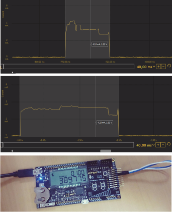
EFM32WG-STK3800.
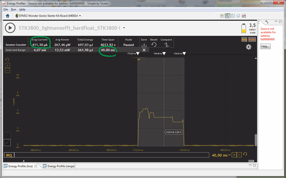
EFM32WG990F256 49 , — 411 . Cortex-M3, DSP- FPU- .
EFM32WG990F256 EFM32GG990F1024,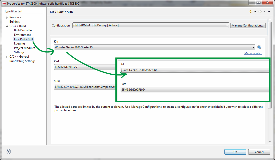
, cortex-m3 cortex-m4,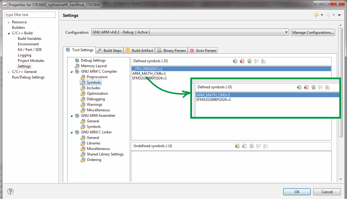
fpu.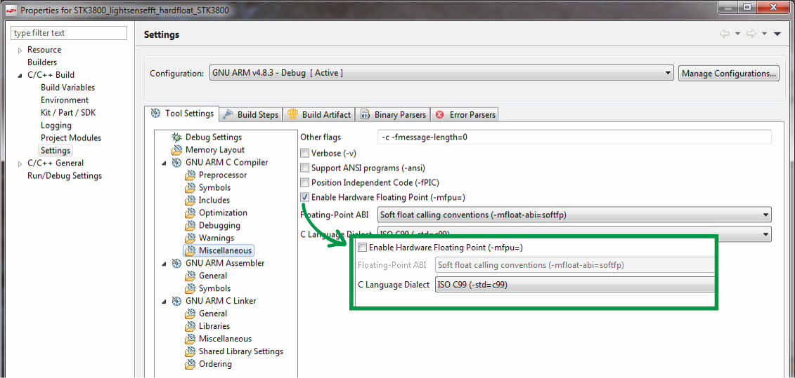
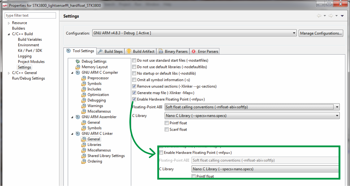
, IDE , , .
, .

: 48 , , .
, . «» . Cortex-M3 2.2 , .
, , Cortex-M3, , .
, .
Source: https://habr.com/ru/post/277491/
All Articles