Like this - to be a software developer for cars. Part 2/2
In the first part of the series, we started developing a servo-driven system, at least mentally. I showed a model of the system on which all the elements and the connections between them are clearly visible.
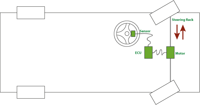
So how do parts of our system connect? Thanks to the FlexRay protocol with an electronic control unit (ECU), the steering wheel is connected to the position sensor. Unlike a conventional sensor that regulates voltage according to temperature, the smart sensor communicates perfectly with FlexRay.
')
In modern cars, as a rule, two types of network technologies are used: CAN and FlexRay. FlexRay is CAN successor. The main advantage of FlexRay is that you can accurately determine the time of transmission of a particular signal, that is, the protocol is deterministic. Using this network, individual vehicle systems, whether brake, steering, or other smart sensor units, continuously exchange the necessary information, which guarantees uninterrupted operation of the car.
The usual FlexRay protocol launch scheme is a process of allocating time to slots, each of which is responsible for sending specific signals or indicators. The protocol sets its rhythm in the course of measuring physical parameters, sending and processing information, as well as regulating the operation of sensors. In the diagram you can see the repetitive FlexRay slots, thanks to which data is transmitted via the bus.
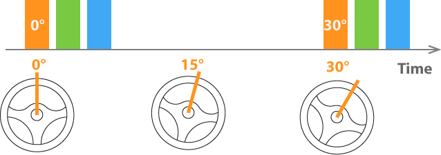
So, the steering angle sensor should send the current figures, when the corresponding slot is in line, not a second sooner or later. Since the standard data sending time is 10 milliseconds, the above diagram had to greatly exaggerate the possible change in the position of the rudder. And the driver will not be able to turn the steering wheel by 5 ° so quickly. But for clarity, we stick to this example.
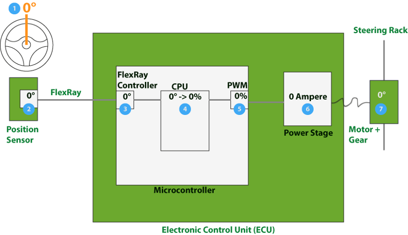
In our microcontroller, a FlexRay controller is provided that accepts values periodically coming from the rudder position sensor. As you have probably guessed, the program for which the processor is responsible also reads and processes FlexRay data from time to time. In this case, processing refers to determining the position of the toothed rack (see diagram above) depending on the angle of rotation of the steering wheel. The mathematical formula allows you to calculate the appropriate mode of operation of the engine, based on the position of the rail. And here even gear shifting is taken into account.
Position Sensor - FlexRay - FlexRay Controller - Processor - PWM - Transmission - Steering rail
You may have noticed the unfamiliar PWM block. This is pulse-width modulation (PWM), which allows to regulate the current supply to the power amplifier - it is also responsible for the motor power supply. But what is PWM?
PWM - pulse width modulation, a great way to control the power of various electrical devices. In other words, you regulate the ratio of electricity and maximum power, where 0% is the lack of power and 100% is the total power that the power amplifier provides to the engine. And, as always, more information can be found on Wikipedia :
Pulse width modulation (PWM, pulse-width modulation (PWM)) is the process of controlling the power supplied to the load by changing the pulse duty cycle at a constant frequency. There are analog PWM and digital PWM, binary (two-level) PWM, and ternary (three-level) PWM.
What happens when the driver turns the steering wheel? At some point, the software running on the processor receives information about the new steering position and generates the PWM value that is needed to start the engine. He, in turn, moves the steering rack. In the example below, the driver turns the steering wheel by 5 ° (1). The sensor analyzes the position and sends the corresponding value on the FlexRay channel (2). Our FlexRay controller receives data (3), on the basis of which the program calculates the appropriate PWM parameters (4) and sets them to the PWM module of the microcontroller (5). The PWM module regulates the flow of electricity, which in turn sets the engine power determined by the power amplifier (6). The current drives the motor (7), and it moves the steering rack (8).

Position Sensor-FlexRay- controller FlexRay-Processor-PWM-Transmission-Steering Rack
Now you know that the previous example involved many different physical calculations and elements. For example, somehow you need to bring% PWM from the degree of rotation of the steering wheel. It is important to consider the current position of the engine, because it is only so clear in which direction and with which speed the engine will have to be started. But, unfortunately, this is a topic of control technology, which I did not plan to cover in this article.
Although I am an architect by profession, software development gives me great pleasure, though, of course, most of all I like to study software architecture that supports the functioning of the system as a whole. Gradually, you realize that the software architecture has to adapt to the rhythm of the system, and it would probably be easier if everything was reduced to a single rhythm. But, no, there are several of them, and they are closely interrelated. For example, the rhythm corresponding to the engine is much faster than the rhythm of the communication channel, so that when you turn the steering wheel, the movement is smooth, without jerks.
Rhythmic software architecture
Thus, the software environment requires rhythmic signal processing. Rhythm implies the existence of certain cycles in the program. Have you ever considered the architecture of an embedded application? If not, do not be alarmed. We start the dive.
Let's analyze how we can separate our program running on the processor from the image above (see illustration of the steering wheel rotation). If you think about the tasks of the application components, you will obviously notice that we are dealing with 3 blocks: one for receiving the FlexRay signal, one for determining the PWM value based on the FlexRay data and one for adjusting the total PWM power. In the following diagram, these components are superimposed on the microcontroller and voila, the multi-tier software architecture is ready.
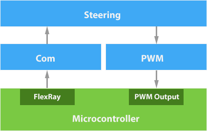
“Com” is used to denote communication lines: this element reads the signal from the FlexRay controller that is part of the microcontroller. It also checks the correctness of the signal transmission (for example, by auto-summarizing data) and transfers it to the rest of the program's components in the form of rudder position indicators. Thanks to a smart algorithm, which had to work hard over one year, the element “Steering” takes this value and calculates the necessary PWM parameters. I'm not kidding, the development of such an algorithm can take a lot of time, because driving is at stake. And, therefore, it is necessary to take into account the mass of variables relevant to certain driving conditions. But back to multi-tier architecture - PWM remained. This PWM component reads the received information about sets the total power of the PWM microcontroller.
And a couple of words about the concept of synchronization. New data comes in every time FlexRay receives a corresponding signal and if it is every 10 milliseconds, the picture is as follows:
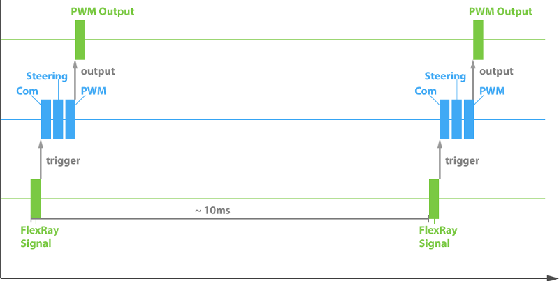
Receiving a FlexRay signal triggers 3 interdependent functions or components. Then determined the total power of the PWM. And all this is repeated every 10 milliseconds. Here you have the rhythm of the software.
Having received the total values from the program, calculated on the basis of the initial data, we get the following diagram:
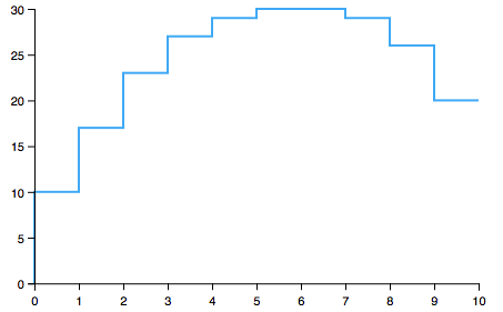
PWM is calculated and adjusted every 10 milliseconds, which means that we coped with the first stage. Now you can turn the car!
As you may have guessed, with such results, the engine obviously will not work smoothly. So it's better:

In the meantime, the driver clearly does not like the trembling of the front wheels when turning the steering wheel. We'll have to refine the architecture of the program. This is what we devote to the new section of the series. I hope you liked the prepared materials, and you will continue to follow the news. Moreover, I am sure that now you, with more, have figured out the principles of building software architecture for cars. As we said, it is determined by the environment or context of the system.
From the translator:
While this is the second and last post about the automotive software from the author of the original text, but I will closely follow the updates in his blog on Medium.
Thanks for attention.
So how do parts of our system connect? Thanks to the FlexRay protocol with an electronic control unit (ECU), the steering wheel is connected to the position sensor. Unlike a conventional sensor that regulates voltage according to temperature, the smart sensor communicates perfectly with FlexRay.
')
In modern cars, as a rule, two types of network technologies are used: CAN and FlexRay. FlexRay is CAN successor. The main advantage of FlexRay is that you can accurately determine the time of transmission of a particular signal, that is, the protocol is deterministic. Using this network, individual vehicle systems, whether brake, steering, or other smart sensor units, continuously exchange the necessary information, which guarantees uninterrupted operation of the car.
The usual FlexRay protocol launch scheme is a process of allocating time to slots, each of which is responsible for sending specific signals or indicators. The protocol sets its rhythm in the course of measuring physical parameters, sending and processing information, as well as regulating the operation of sensors. In the diagram you can see the repetitive FlexRay slots, thanks to which data is transmitted via the bus.
So, the steering angle sensor should send the current figures, when the corresponding slot is in line, not a second sooner or later. Since the standard data sending time is 10 milliseconds, the above diagram had to greatly exaggerate the possible change in the position of the rudder. And the driver will not be able to turn the steering wheel by 5 ° so quickly. But for clarity, we stick to this example.
In our microcontroller, a FlexRay controller is provided that accepts values periodically coming from the rudder position sensor. As you have probably guessed, the program for which the processor is responsible also reads and processes FlexRay data from time to time. In this case, processing refers to determining the position of the toothed rack (see diagram above) depending on the angle of rotation of the steering wheel. The mathematical formula allows you to calculate the appropriate mode of operation of the engine, based on the position of the rail. And here even gear shifting is taken into account.
Position Sensor - FlexRay - FlexRay Controller - Processor - PWM - Transmission - Steering rail
You may have noticed the unfamiliar PWM block. This is pulse-width modulation (PWM), which allows to regulate the current supply to the power amplifier - it is also responsible for the motor power supply. But what is PWM?
PWM - pulse width modulation, a great way to control the power of various electrical devices. In other words, you regulate the ratio of electricity and maximum power, where 0% is the lack of power and 100% is the total power that the power amplifier provides to the engine. And, as always, more information can be found on Wikipedia :
Pulse width modulation (PWM, pulse-width modulation (PWM)) is the process of controlling the power supplied to the load by changing the pulse duty cycle at a constant frequency. There are analog PWM and digital PWM, binary (two-level) PWM, and ternary (three-level) PWM.
What happens when the driver turns the steering wheel? At some point, the software running on the processor receives information about the new steering position and generates the PWM value that is needed to start the engine. He, in turn, moves the steering rack. In the example below, the driver turns the steering wheel by 5 ° (1). The sensor analyzes the position and sends the corresponding value on the FlexRay channel (2). Our FlexRay controller receives data (3), on the basis of which the program calculates the appropriate PWM parameters (4) and sets them to the PWM module of the microcontroller (5). The PWM module regulates the flow of electricity, which in turn sets the engine power determined by the power amplifier (6). The current drives the motor (7), and it moves the steering rack (8).
Position Sensor-FlexRay- controller FlexRay-Processor-PWM-Transmission-Steering Rack
Now you know that the previous example involved many different physical calculations and elements. For example, somehow you need to bring% PWM from the degree of rotation of the steering wheel. It is important to consider the current position of the engine, because it is only so clear in which direction and with which speed the engine will have to be started. But, unfortunately, this is a topic of control technology, which I did not plan to cover in this article.
Although I am an architect by profession, software development gives me great pleasure, though, of course, most of all I like to study software architecture that supports the functioning of the system as a whole. Gradually, you realize that the software architecture has to adapt to the rhythm of the system, and it would probably be easier if everything was reduced to a single rhythm. But, no, there are several of them, and they are closely interrelated. For example, the rhythm corresponding to the engine is much faster than the rhythm of the communication channel, so that when you turn the steering wheel, the movement is smooth, without jerks.
Rhythmic software architecture
Thus, the software environment requires rhythmic signal processing. Rhythm implies the existence of certain cycles in the program. Have you ever considered the architecture of an embedded application? If not, do not be alarmed. We start the dive.
Let's analyze how we can separate our program running on the processor from the image above (see illustration of the steering wheel rotation). If you think about the tasks of the application components, you will obviously notice that we are dealing with 3 blocks: one for receiving the FlexRay signal, one for determining the PWM value based on the FlexRay data and one for adjusting the total PWM power. In the following diagram, these components are superimposed on the microcontroller and voila, the multi-tier software architecture is ready.
“Com” is used to denote communication lines: this element reads the signal from the FlexRay controller that is part of the microcontroller. It also checks the correctness of the signal transmission (for example, by auto-summarizing data) and transfers it to the rest of the program's components in the form of rudder position indicators. Thanks to a smart algorithm, which had to work hard over one year, the element “Steering” takes this value and calculates the necessary PWM parameters. I'm not kidding, the development of such an algorithm can take a lot of time, because driving is at stake. And, therefore, it is necessary to take into account the mass of variables relevant to certain driving conditions. But back to multi-tier architecture - PWM remained. This PWM component reads the received information about sets the total power of the PWM microcontroller.
And a couple of words about the concept of synchronization. New data comes in every time FlexRay receives a corresponding signal and if it is every 10 milliseconds, the picture is as follows:
Receiving a FlexRay signal triggers 3 interdependent functions or components. Then determined the total power of the PWM. And all this is repeated every 10 milliseconds. Here you have the rhythm of the software.
Having received the total values from the program, calculated on the basis of the initial data, we get the following diagram:
PWM is calculated and adjusted every 10 milliseconds, which means that we coped with the first stage. Now you can turn the car!
As you may have guessed, with such results, the engine obviously will not work smoothly. So it's better:
In the meantime, the driver clearly does not like the trembling of the front wheels when turning the steering wheel. We'll have to refine the architecture of the program. This is what we devote to the new section of the series. I hope you liked the prepared materials, and you will continue to follow the news. Moreover, I am sure that now you, with more, have figured out the principles of building software architecture for cars. As we said, it is determined by the environment or context of the system.
From the translator:
While this is the second and last post about the automotive software from the author of the original text, but I will closely follow the updates in his blog on Medium.
Thanks for attention.
Source: https://habr.com/ru/post/277315/
All Articles