Initial Setup of Extreme Networks Wireless Controllers
The previous review dealt with the entire line of Wi-Fi Extreme Networks solutions for wireless access network. The purpose of this review is to familiarize yourself with the configuration of Extreme Networks ExtremeWireless (IdentiFi) series wireless controllers.
The review consists of 4 large sections with detailed screenshots and tincture instructions:
- Overview of settings for the wireless controller
- Wireless and network topology
- Example of setting up the B @ AP topology
- Work with the Initial Installation Wizard (Basic Installation Wizard)
')
The following documents can be found on the Extreme Networks website for each software revision:
• Wireless CLI Reference Guide - the main document for configuring the controller through the console;
• Wireless Getting Started Guide - document on the initial launch of Extreme Networks wireless equipment in English;
• Wireless Maintenance Guide - maintenance manual for controllers;
• Wireless Open Source Declaration - This guide lists open source software used in wireless controllers and access points;
• Wireless User Guide is a basic guide that describes how to install, configure, and manage wireless controllers and access points;
Documents Wireless User Guide and Wireless CLI Reference Guide are the main documents for setting up Extreme Networks wireless controllers.
Overview of settings for the wireless controller
1. Before you begin to configure your wireless equipment: you must have an understanding of SSID, security settings, and policies.
2. It is necessary to prepare the network: make sure that external servers such as DHCP and RADIUS are available and operable (if they are available).
3. Install the wireless controller, more information is on the manufacturer's website:
• IdentiFi Wireless Appliance C5210 Quick Reference.
• IdentiFi Wireless Appliance C25 Quick Reference.
• IdentiFi Wireless Appliance C35 Quick Reference.
• IdentiFi Wireless Virtual Gateway V2110 Installation Guide.
4. Perform initial setup of access to the wireless controller.
1) First you need to determine the type of connection between the controller and the switching network.
a) Determine which physical interfaces (L2 ports) will be connected.
b) Determine which VLANs will be associated with the physical interfaces.
c) Determine which Service (virtual) topologies will distribute the service (determine the correspondence between topologies that distribute services and services — SSID, etc.), and which of the physical interfaces will transmit these services through VLANs. L2 Port Summary - shows a list of matching VLANs and physical interfaces.
2) Configure remote access to the control port for the controller:
• You can connect to the controller through the management port.
3) Topologies directly connected to physical (L2) ports are explicitly defined using the “Physical” tag in their Mode.

If you use tagged VLAN! for topology, please make sure that the tags in the VLANs on the switches and the tag on the controller match.
4) To control the controller through a physical interface, you must put a mark on the management capability (Management Traffic)

5) Configure the IP address on the physical interface.
5. Set the system time - NTP server (optional)
For more information, see the “Configuring the Network Time Using an NTP Server” section in the Extreme Networks Wireless User Guide.
6. Enter the activation key on the controller.
7. Expanding the capabilities of virtual controllers - Small / Medium / Large (optional)
8. Configure routing (optional)
9. Configure VNS.
A VNS is created through the binding of a WLAN service to one or more policies that apply to wireless stations by default. The policy can be changed after authentication on the external interface. VNS integrates WLAN service, topology and access policy.
Policies define the allowed level of user access, bandwidth limitations, and the topology in which the user is located. Global policies are assigned to the VNS, or can be explicitly assigned after verifying user authentication (RADIUS Access-Accept message).
Steps for configuring VNS:
1) Select: wireless service (access), encryption type, topology, and connection points — such as switch ports (the VLAN settings on the switch and on the tagged port of the controller must match). It is also necessary to configure the wired network so that users of the wireless network have access to wired infrastructure resources.
2) Define Topologies: the topology describes the interaction of the wireless controller and the wired network (switch), so the VLANs and ports of the controller connection must be matched with the corresponding ports of the switch.
3) Define Policies: Policies are usually associated with topology. Policies define the allowed level of user access, bandwidth restrictions.
4) Define Class of Service (CoS): CoS determines the priority of transmission of user traffic on the network when bandwidth limits are exceeded.
5) Define WLAN service:
• Select the access point / radio channel on which the service will operate.
• Configure the type of user credential authentication for this service ((None, Internal, Captive Portal, External Captive Portal, Guest Portal, or 802.1x [EAP])
6) Create a VNS connecting the WLAN service with the policy that is used for the default assignment when a user joins the network.
7) Install one or more virtual subnets on the controller. For each VNS, configure in sequence:
• Topology - select one of the topology types:
| Type of | Topology Configuration Steps |
| Bridged @ Controller | Specify the VLAN for the interface. |
| Select physical port, on which is tagged VLAN. | |
| If L3 settings are needed, Specify the IP address and subnet mask. | |
| Determine whether the controller is the DHCP server for the network segment; if so, set up DHCP server settings. | |
| Determine whether the controller is DHCP relay; if so, configure the IP address of the DHCP server. | |
| Routed @ Controller | Specify the IP address and mask subnet. |
| Specify DHCP server options for the network segment; If the controller will be the DHCP server for the segment network, configure DHCP server settings; If the controller will be DHCP relay for the network segment, configure the IP address of the DHCP server. | |
| Bridged @ AP | Set as untagged or specify a tag from the range of 1-4094. |
| Specify the VLAN number to issue a tag on the AP. |
• Policy - select the topology that will be used on the network and be associated with policies, configure the filters:
• Define access policies for users on the network.
• For Bridge @ Controller and Route @ Controller topologies, filtering can be performed both on the controller and on access points
• Is bandwidth required for users on the network (default speed is unlimited)?
• Class of Service - Class of Service (CoS) defines the following parameters for traffic:
• Rate limits - Maximum channel capacity (channel speed limit)
• Transmit queue assignments - determines how quickly the prioritized packet will be sent over the network relative to other traffic.
• Priority remarking behavior - priority remarking affects the priority of sending packets in downstream switches.
• Class of Service (CoS) takes effect when the channel speed limits are exceeded. All incoming packets follow the rules defined in CoS:
• Each incoming packet is checked for compliance with a set of rules defined by the administrator; the first match found is assigned a corresponding CoS policy. If no match is found, a default CoS rule is assigned based on the policy.
• Apply new marking on the package in accordance with the marking defined in the CoS.
• Will the traffic exceed the data transfer rate assigned to the CoS. If so, the packet will be dropped.
• If the packet is not dropped, the priority queue used for data transmission is selected based on the CoS.
• Determine the type of service provided. Choose a standard service that provides wireless access to the network.
• Determine the service name - SSID, which will be distributed by access points.
• Select access points and radio interfaces (2.4 GHz, 5 GHz) through which the service should be provided.
• WLAN Service

• Select the authentication method that users must successfully complete in order to gain access to the wireless network:
| Authentication method | Topology Configuration Steps |
| MBA (MAC address based authentication) | The MAC address of the device must be explicitly allowed to register with the RADIUS server. |
| Captive Portal: | |
| Internal | Configure the authentication page settings on the internal Captive Portal. |
| External | Configure connection settings to interact with an external authentication server. |
| Guest Portal | Identify the credentials that will provide access to the service. |
| RADIUS Accounting | Determine the RADUIS authentication server where statistics will be sent. |
- Privacy tab: Select a wireless network encryption method (None, WEP, WPA / PSK, DynWep, WPA / EAP).
- Configure QoS (optional)
• VNS
- Select WLAN service for VNS.
- Configure a security policy for unauthenticated users that will be initially assigned to a user associated with a WLAN service.
- Configure the security policy for users who have been authenticated; this policy will be assigned to the user after successful authentication.
- Activate VNS service
10. Install the access points, register them on the controller and assign the WLAN Service to the access points.
Wireless and network topology

Initial configuration of the wireless controller
Hardware Wireless Controllers C5210, C25, C35
Initial configuration of the management port:
For hardware controllers, configuring the control port is an optional step. If you do not intend to connect to the controller via the management port (you do not need to change the IP address settings), you can skip this step and use the default settings.
Access to the hardware controller via the GUI interface by default:
192.168.10.1 : 5825
Login: admin
Password: abc123
Access to Wi-Fi controller via Web interface:
1) Manually assign an unused IP address and network mask to a computer (from the same subnet as the controller control port). If you use the default network, you can assign an IP address from the range 192.168.10.2 - 192.168.10.254.
2) Connect the computer to the control port of the controller using a cross-over RJ45 Ethernet cable (if it is a hardware controller).
3) Start the Web-browser and write in the address bar: https: //: 5825
We agree with the exception for the certificate.

4) Enter the controller web page under your Login / Password:

5) Optional . You can configure the controller through the “Basic Installation Wizard”. Or skip the installation wizard, manually setting all parameters later.

6) View of the controller home page, after the first launch:

7) At any time, you can run the installation wizard via the Controller -> Administration -> Installation Wizard menu

Installing the activation key on the controller
Activation key:
• Provides the controller with information about the regulatory domain in which the controller provides wireless service. A regulatory domain is a list of countries with frequency response parameters for configuring access points.
• It is registered by the MAC address of the control port of the controller.
• Includes the basic number of access points connected to the controller (the number varies depending on the platform). You can expand the number of connected access points by purchasing additional Capacity Upgrade licenses.
Attention!
Each time a region of the regulatory domain changes on the controller, all access points automatically switch to automatic channel selection mode in order to prevent possible violations of radio frequency requirements in the region. All settings that have been configured manually will be reset and lost. You must install a license key before configuring.
The procedure for installing a license key on the controller:
1) Through the home page, we go to the licensing section to change the Demo license to the one we need. You can also go to: Controller -> Administration -> Software Maintenance -> EWC Product Keys

2) After installing the license, you can continue to configure the controller (in the example, a license was entered with a trial period of 180 days):

Software update on controller
The controller software can be updated in two ways:
• Locally - the software is already loaded on the device - you only need to update the controller. Or download the image from the USB drive to the controller and perform the update.
• Remotely - download an image from a remote FTP server (or SCP) and perform an update.
The updater downloads the software image file from the FTP server, unpacks it and installs directly on the system, without saving a local copy of the software file.
You can update the controller through the web-interface (GUI) or through the management console (CLI).
SCP can only be used to upload a software image to the controller; the “Upgrade now” button will not be available.
Always back up your existing software version. This will allow you to revert to the previous version, if necessary.
A more detailed description of software updates can be found in the Wireless Maintenance Guide.
In this example, we consider the option of updating the controller remotely via an FTP server.
1) In order to go to the software update menu, it is necessary to go to the “Controller” tab from the main menu.
2) Then "Administration" -> "Software Maintenance"
3) Select the “Remote” menu:

4) Sequentially fill in the necessary data on the FTP server from which you are going to download the software:
• Protocol - FTP.
• Server - the IP address from which you are going to download the software.
• User ID - Login, which has rights to access the server.
• Password - the password for the User ID.
• Confirm - Confirm the password for logging into the FTP server. This field is used to verify correct password entry.
• Directory - The directory in which the software file is located.
• Filename - The name of the file to be downloaded.
5) Optional. You can set a schedule for software updates on the controller.
• Select “Schedule Upgrade for”
• Set the month, day, hour, and minute to update.
• Press the “Schedule Upgrade” button that appears and then “Ok” to confirm the updates.
Scheduled update, not a recurring event. The wireless controller allows you to perform scheduled updates only once, then you need to configure it again.
6) Update controller software:
6.1 Click “Upgrade Now” and then “Ok”

After the update, the controller will reboot.
6.2 Or download the image to the controller - to make sure that the file was downloaded correctly, and then perform the update.

Click the “Upgrade Now” button and then “Ok”
View of the update process page:

After the update, the controller will reboot.
7) After the reboot, you can see the installed version of the software:

Configuration example for B @ AP topology
When using Multicast method of determining the access points of the controller, you must disable igmp snooping on the VLAN in which the access points and the physical interface of the controller are located. By physical interface is meant the network port of the controller to which Physical topology is connected.
If you are using external DHCP, configure the options.
An example of setting up a Bridge (Bridge @ access point) topology:
1) In order for the controller to detect access points, it is necessary that the network has a valid DHCP server that will issue parameters to the access points, this may be local DHCP on the controller or a third-party DHCP server on your network.
We configure local DHCP on the controller (in Physical Topology), which will issue IP addresses for TD and wireless clients.
• To do this, first set up the Physical topology. To do this, go to "VNS -> Topologies -> New button (create a new topology, if you have not done this before)":

• Name - specify the name of the topology.
• Mode - specify the topology mode (in this case Physical)
Physical - The physical topology mode is designed to control Extreme Networks access points. And also to manage third-party access points ("3rd party VNS").
VLAN Settings:
• VLAN ID — The VLAN tag number on the wired network to which the controller is connected.
• Untagged / Tagged - we specify the tagged port or not tagged.
• Port - specify the port that is connected to the wired network. (L2 port)
IPv4 options:
• L3 configuration is required if services (for example, DHCP, captive portal, etc.) are required in a configured network segment, or if it is necessary to control the controller via this interface.
• Interface IP - IP address of the connected physical Ethernet port.
• Mask - subnet mask.
• DHCP - rules for using DHCP.
• MTU (maximum transmission unit) - The maximum size of packets transmitted through this port. The default value is 1500.
• AP Registration — specify that the controller can register access points on the network through this interface.
• Management Traffic - specify if it is necessary to control the controller through this interface.
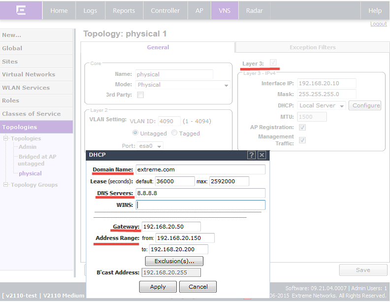
2) Then we specify the parameters for the DHCP server, in accordance with your requirements:
• Domain Name - the name of the external domain of the company.
• Lease - the time for which the IP parameters for the device are issued.
The default value is 36000 seconds (10 hours)
• DNS Servers - DNS server IP address.
• WINS - specify if the DHCP server uses the Windows Internet Naming Service (WINS)
• Gateway - IP address of the gateway for this topology. The controller sends this address to wireless clients that connect to it. Clients will send traffic to the address specified in this field.
• Address Range - the range of addresses issued to DHCP clients.
3) After starting the DHCP server, the AP is associated with the controller.
You can view the status of the AP in the section “AP -> Bulk configuration -> Access Approval”

4) In order for the access point to start using the frequency range allowed in our country, it is necessary to set the region of its “presence” = Ukraine.
“AP -> APs -> All”, then select the desired access point and the “AP Properties” tab in it, section Country = Ukraine.

Changing the region will require restarting the access point.
5) It is also necessary to enable the Radio Interfaces on access points:
“AP -> APs -> All”, then select the desired access point and the tab “Radio 1” / “Radio 2” in it.

6) It is necessary to create the Bridge @ AP topology.
To do this, go to "VNS -> Topologies -> New Button"
Bridged Traffic Locally at AP is a type of topology that is assigned to access points. The access point forwards traffic from the wireless network to the wired network, without the involvement of the controller. The “point of presence” of the wired network in this case is the port of the access point.
• Name - specify the name of the topology.
• Mode — specify the topology mode (in this case, Bridged Traffic Locally at AP)
VLAN Settings:
• VLAN ID — The VLAN tag number on the wired network to which the controller is connected.
• Untagged / Tagged - we specify the tagged port or not tagged.

7) You need to create a role (policy) that will be used in the WLAN service.
To do this, go to "VNS -> Roles -> New button (create a new role)"

You must specify:
• Role Name - the name of the assigned role.
• Access Control - actions performed on the access list in the Policy Rules section:
None - no action for the role.
No change - the default settings.
Allow is the default action for the VLAN / topology.
Deny - any packets that do not fall into the rule will be dropped.
• Default Class of Service — optional, you can specify the CoS settings that will be applied to the wireless client (traffic priorities or bandwidth restrictions).
• Traffic Mirror - traffic mirroring settings.
• Also, if necessary, you can create security policies.
A more detailed description of the security policy settings can be found in the Wireless User Guide, section Policy Rules.

8) Set the WLAN Service
To do this, go to "VNS -> WLAN Services -> New button (create a new WLAN service)"

• Enter a name for the WLAN service (it can also be the SSID name)
• Select the type of service provided (in our case, Standard)
• Standard
• WDS
• Mesh
• Third Party AP
• Remote
• If necessary, change the SSID name (optional)
• Do not forget to press the "Save" button

9) Next, configure the WLAN service, for this:
• Name / SSID - Name and SSID can be changed (optional)
• Default Topology - select the topology by default from the drop-down list (in the example, this is the topology you created earlier) or create a new topology.
The WLAN service uses the topology from the role assigned globally to the VNS, if such a topology in the role is defined. If the topology is not defined in a role, you can assign the existing one as the default topology in this WLAN service. If you do not install the topology yourself, a global default topology will be selected (by default, there is a preconfigured one — Bridged at AP Untagged).
You cannot assign a default topology to WDS, 3rd party, remote WLAN services.
• Set CoS by default (Optional)
• Configure default traffic mirroring (Optional)
• Enable WLAN service - enable button.
• Select the access points to which the WLAN service will be used.
• The choice of access points and their radio interfaces are divided into groups, for ease of selection:
• all radios — assign a WLAN service to all the radio interfaces of all access points.
• radio 1 — assign the WLAN service to the Radio 1 radio interface of all access points.
• radio 2 — assign the WLAN service to the Radio 2 radio interface of all access points.
• local APs — all radios — assign a WLAN service to all the radio interfaces of all local access points.
• local APs - radio 1 — assign the WLAN service to the Radio 1 radio interface of all local access points.
• local APs - radio 2 — assign the WLAN service to the Radio 2 radio interface of all local access points.
• foreign APs — all radios — assign a WLAN service to all radio interfaces of all remote access points.
• foreign APs - radio 1 — assign the WLAN service to Radio 1 radio interface of all remote access points.
• foreign APs - radio 2 — assign the WLAN service to the Radio 2 radio interface of all remote access points.
• clear all selections - Clear all selected points and radio interfaces.
• It is also possible to selectively connect a WLAN service to the radio interfaces of access points (Different WLANs can be connected to different radio interfaces of access points)
• Do not forget to press the "Save" button
10) Select the encryption type and authentication method (optional)

11) Set the VNS in which the WLAN service will work.
To do this, go to "VNS -> Virtual Networks -> New button (create a new VNS)"


• Enter a name for the VNS
• Select WLAN service (in our case EN-SSID)
• Specify the policy that will be applied to an unauthenticated user.
• Specify the policy that will be applied to the user after authentication.
• Turn on VNS service.
• Do not forget to press the "Save" button
12) After that, the TDs start distributing IP addresses to clients from the subnet in which they are located.
Working with the Basic Installation Wizard
Setup via the initial installation wizard:
1) Connect to the controller
2) Start the Controller -> Administration -> Installation Wizard from the main menu.

3) View of the Basic Installation Wizard:

4) In the window that appears, select the time zone settings (timezone):
• Continent or Ocean — select the appropriate large-scale geographic grouping for the time zone. (Europe / America / and so on.)
• Country — select the appropriate country for your time zone. The selection of the list of countries changes depending on the Continent or Ocean drop-down menu.
• Time Zone Region - Select the appropriate time zone region for the selected country from the drop-down menu.
5) Set the time on the wireless controller:
• Set time (manual setting) - set the parameters: year, month, day, hour and minute.
• Run local NTP Server - in order to use the controller as an NTP server, select this item. Also specify the IP address or domain name for the NTP server.
• Use NTP - allows you to synchronize the time of the controller and the NTP server on your network. You must specify the IP address of the remote NTP server.
The address field for the IP address of the NTP server supports both IPv4 and IPv6.
6) In the Topology Configuration section, the topology name, port, IP address and network mask for the physical interface of the controller are specified, and the VLAN ID is shown only as a Read-Only value.
For information on how to obtain a temporary IP address from the network, you can click on the link “To obtain a temporary IP address”.
7) View of the initial installation wizard:

8) In the section for choosing the parameters of the management port (Management Port section), you must ensure that the parameters of the management port are correct and can be changed if necessary.
• Static IP Address - displays the IPv4 control port address settings
• Netmask - displays the subnet mask settings.
• Gateway — displays the default gateway settings.
• Static IPv6 Address — Displays the management port IPv6 address settings.
• Prefix Length — displays the length of the IPv6 prefix. Maximum 64 bits.
• Gateway — Displays default gateway settings.
9) In the SNMP section - you can select the mode of connection to the controller (V2c or V3).
If you select V2c, the Community fields will appear to fill in:
• Read Community — enter the password that is used for the Read-only mode when interacting via SNMP.
• Write Community - enter the password that is used for the write mode when communicating via SNMP.
• Trap Destination - enter the IP address of the server used as the network manager that receives SNMP messages.
If you selected V3, you will need to enter the settings later in the Controller -> Network -> SNMP section.
For more information, see the Wireless User Guide.
10) Syslog Server:
• Enable - allows you to enable Syslog server.
• IP Address - enter the IP address for the Syslog server.
11) OSPF section:
• OSPF enabled on VNS, allowing the controller to dynamically select routes for traffic.
• Area ID - the type of area to which the controller is connected. The default area 0.0.0.0 is set by default.
12) The “Services” initial installation wizard view:

13) RADIUS server section
• Server Alias - enter the name of the RADIUS authentication server.
• IP Address — enter the IP address of the RADIUS authentication server.
• Shared Secret — enter the password that is used to verify the connection between the wireless controller and the RADIUS server.
14) Section Mobility - includes the possibility of seamless roaming, allows users to move between different access points (controllers), without interrupting the connection.
More information is in the Wireless User Guide.
15) Default VNS section - allows you to enable pre-configured default VNS.
The VNS list is displayed in the same section.
16) After moving to the final page, you will need to change the user's password or leave it by default.
We strongly recommend that you change the default password value.

17. After clicking the Save and Close button, the controller will reboot and apply all changes.
That's all!
Distribution of Extreme Netwroks solutions in Ukraine, Belarus, CIS countries.
Extreme Networks training courses
MUK-Service - all types of IT repair: warranty, non-warranty repair, sale of spare parts, contract service
Source: https://habr.com/ru/post/277035/
All Articles