Recommendations for Designing the User Interface of RealSense Applications
Intel® RealSense ™ technology supports two types of camera depth: a front view camera, a short-range (F200) is designed for installation on laptops, ultrabooks, transformers and all-in-one computers; rear-view camera, long-range (R200) is designed for installation on tablets and as a separate removable device. Both cameras are available as stand-alone peripherals and are embedded in computer devices currently available on the market. When using Intel RealSense technology to develop applications for such devices, it should be remembered that the principle of interaction with three-dimensional applications without tactile feedback differs significantly from the model of work to which developers are accustomed to creating applications for touch control.
In this article, we describe some of the common principles and problems of user interfaces for the F200 and R200 cameras and show how you can build visual feedback into your applications using the Intel® RealSense ™ SDK API.
Guidelines for creating user interfaces and using the API for the F200 camera
Result 1. Understanding the volumetric shooting space and interaction areas for laptops and all-in-one computers
UI usage scenario
Consider the use cases shown in Fig. one.
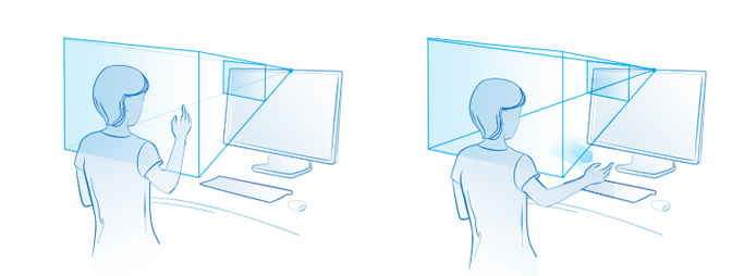
Figure 1. Surround space
The pyramid emanating from the camera in this figure is what is called the volumetric shooting space or field of view of the camera. For the F200, the volumetric shooting space is determined by the deviations from the horizontal and vertical axes of the camera, as well as the effective distance between the user and the camera. If the user moves beyond this pyramid, the camera will not be able to track the interaction mode. Below for reference is a table with parameters of the field of view.
| Parameter | Range |
|---|---|
| Effective Gesture Recognition Range | 0.2–0.6 m |
| Effective face recognition range | 0.35–1.2 m |
| Field of view of a color image camera, degrees | 77 x 43 x 70 (cone) |
| Infrared (IR) camera field of view, degrees | 90 x 59 x 73 (cone) IR illuminator field of view = n / d x 56 x 72 (pyramid) |
| Color Image Resolution | Up to 1080p at a frame rate of 30 frames per second (fps) |
| Depth Map Resolution | Up to 640 x 480 at 60 fps |
The color imaging camera and the depth camera in the F200 device have different resolutions, so developers should consider the volumetric shooting space for the intended modes of operation with the application. As shown in the table above, the effective range of gesture recognition is small, whereas face tracking works at a greater distance.
')
Why is this important in terms of user interface? End users have no idea how the camera “sees” them. Since they know about the interaction zones, this can lead to irritation when working with the application, since it is impossible to determine exactly what the problem arose. The image on the left in Fig. 1 user’s hand is in the camera’s field of view, and the image on the right is out of sight; in this case, tracking may be lost. The problem is further complicated if the application uses control using both hands or several control modes at once, for example, using face and hands simultaneously. Also consider changing the camera's field of view when you deploy the application on devices of different sizes, such as laptops and all-in-one computers: in the latter case, the interaction zone will be located higher than on laptops. In fig. 2 shows the different scenarios in which users are in front of different devices.

Figure 2. Camera field of view and device size
Information about these parameters will help build an effective feedback mechanism into the application to provide users with clear instructions on how to use the device and the camera correctly. Now let's see how to get some of these parameters of the visual field in the application via the SDK.
Technical implementation
The Intel RealSense SDK provides an API for capturing camera field of view and range data. The QueryColorFieldOfView and QueryDepthFieldOfView APIs work in the device interface regardless of the device type. This is how the code is implemented.
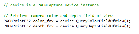
Although the returned data structure has the format PXCPointF32, the returned values indicate the angles of X (horizontal view) and Y (vertical view) in degrees. These are the manufacturer-specified values for this camera model, and not software-configured on the device.
The next parameter of the volumetric shooting space is the distance. The QueryDepthSensorRange API returns the range value in millimeters. This value is also set by the manufacturer by default for this model, and is not programmed on a specific device.
Knowledge of these APIs and how to implement them in code will help create an effective feedback system for users. In fig. 3 and 4 show examples of visual feedback for volumetric shooting.
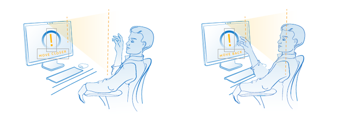
Figure 3. Camera distance tips
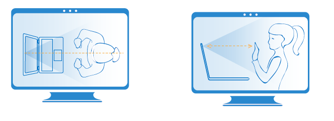
Figure 4. Schematic representation of the surrounding world
Simple hints indicate the near and far borders of the interaction zone. Without prompts, the user simply will not understand what needs to be done if the system stops responding to his actions. Filter distance data and show a prompt after a short delay. Also, use hints and tips instead of error notifications. A schematic depiction of the surrounding world will help users navigate and become familiar with the concepts of the depth camera interaction zone.
It is recommended to use such schematic images on the help screens and in educational screensavers, as well as in games, the users of which can work with the camera for the first time. For maximum efficiency, you should show a schematic depiction of the surrounding world only when educating users and on help screens. Instructions should be simple and comprehensible, in their preparation it is necessary to focus on the intended audience of the application.
Instead of the APIs listed above, you can use the alerts provided in each SDK to record specific user actions. Consider, for example, the following solution for facial recognition. The following table lists the PXC [M] FaceData module alerts.
As you already know, the SDK supports detection of up to 4 people in sight. Using the face ID, you can receive alerts related to each person, depending on the needs of the application. Tracking can also be completely lost (for example, if the face has moved into the camera’s field of view, and then out of sight at a speed that is too high to track). In such a scenario, you can use the data from the survey shooting space along with alerts to create a reliable feedback mechanism for users.
| Alert Type | Description |
|---|---|
| ALERT_NEW_FACE_DETECTED | New face detected. |
| ALERT_FACE_NOT_DETECTED | There is no face in the scene. |
| ALERT_FACE_OUT_OF_FOV | The face is out of sight of the camera. |
| ALERT_FACE_BACK_TO_FOV | The face is back in sight of the camera. |
| ALERT_FACE_LOST | Lost face tracking. |
The SDK also allows you to detect an overlay, i.e. cases where the object to be removed is blocked by a foreign object. For a description of unsupported and partially supported scenarios, see the F200 Camera User Interface Design Guide. No matter what type of overlay you are trying to track, the next set of alerts will be very useful.
| Alert Type | Description |
|---|---|
| ALERT_FACE_OCCLUDED | The face is blocked. |
| ALERT_FACE_NO_LONGER_OCCLUDED | The face is no longer blocked. |
| ALERT_FACE_ATTACHED_OBJECT | A person is blocked by an object, such as a hand. |
| ALERT_FACE_OBJECT_NO_LONGER_ATTACHED | The face is no longer blocked by any object. |
Now let's move on to alerts in the hand tracking module. They are available in the PXC [M] HandData module of the SDK. As you can see, some of these alerts also implicitly involve the determination of the range (remember about the different range of action of the face recognition modules and hand recognition modules).
| Alert Name | Description |
|---|---|
| ALERT_HAND_OUT_OF_BORDERS | The monitored hand is outside the two-dimensional bounding box or the three-dimensional bounding cube specified by the user. |
| ALERT_HAND_INSIDE_BORDERS | The tracked hand has returned to the inside of the two-dimensional bounding box or the three-dimensional bounding cube specified by the user. |
| ALERT_HAND_TOO_FAR | Tracked arm is too far from the camera. |
| ALERT_HAND_TOO_CLOSE | The tracked arm is too close to the camera. |
| ALERT_HAND_DETECTED | The monitored hand is recognized, its mark is available. |
| ALERT_HAND_NOTE_DETECTED | A previously detected arm is lost because it is either out of sight or blocked. |
| And many others... | See the documentation. |
Now you know what features the SDK provides, and you can effortlessly apply them in the application code. An example is shown in the following code snippet.
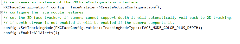
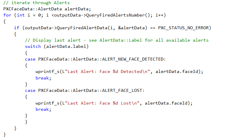
Replace wprintf_s instructions with visual feedback implementation logic. You can include not all alerts, but only some of them, as shown below.

In fig. 5 and 6 show examples of effective visual feedback using alerts.
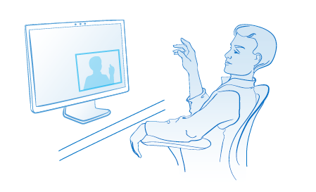
Figure 5. User image in camera view
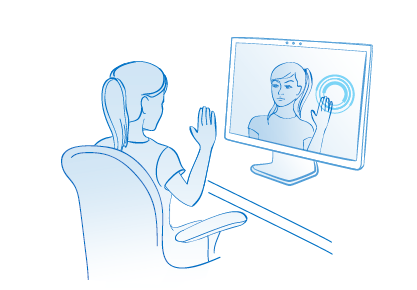
Figure 6. Overlay user image
API references in the SDK documentation
- QueryColorFieldOfView
- QueryDepthFieldOfView
- QueryDepthSensorRange
- Alerts on the field of view of facial recognition module
- Handshake module field of view alerts
Result 2. Reduced user fatigue.
User Interface Use Case: Select the appropriate input method for the required accuracy.
When creating applications using the Intel RealSense SDK, it is important to remember the features of the input modes. The selection of suitable input modes for different scenarios plays a crucial role in the operation of the application. Input using the keyboard, mouse and touch screen is highly accurate, while input using gestures has low accuracy. For example, to work with applications that require a lot of work with data, it is preferable to use keyboard and mouse input, rather than gestures. Try to imagine what it will try to select a specific cell in Excel with your finger instead of the mouse (see. Fig. 7). Such actions will not cause anything but extreme irritation and fatigue of the user. When trying to perform precise actions, users naturally tighten their muscles, which, in turn, leads to increased fatigue.

Figure 7. Choosing the right input method
You can use the touch controls or the mouse to select items in the menu. The input modes supported by the Intel RealSense SDK provide a direct, natural touch-free interaction mechanism and allow you to create exciting applications. Use these modes in such a way that it does not require many repeated gestures. For the use of gestures, permanent actions are best suited, in which mistakes will not lead to unwanted risk.
Selecting the direction of movement of gestures
It is recommended to use gestures directed horizontally or in an arc. If a choice is available, then for the convenience of users, try to use horizontal motions instead of vertical motions. In addition, do not use actions that force users to raise their arms above shoulder level. Remember the effect of "gorilla hands"?
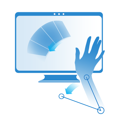
Figure 8. Selecting the direction of movement of gestures
The choice of relative or absolute movement
Allow relative movement instead of absolute movement in all expedient cases. With relative movement, the user can “reset” the arrangement of the virtual hand on the screen in order to achieve a more comfortable position of his own hand in front of the camera. This is about the same as raising the mouse and rearranging it from the edge of the pad to the middle if you need to move the pointer further. In absolute motion, the relationship between the position of the pointer on the screen and the position of the hand on the screen is always preserved. Applications should use a model of movement that is most appropriate for each specific context.
Understanding speed
Part of the accuracy problem is the speed factor. If users move their hands too fast in front of the camera, then there is a risk of complete loss of tracking, since the hands may be out of the shooting volume space. When used in applications gestures with fast movements increases user fatigue and increases the risk of errors. Therefore, it is very important to take into account the speed factor and its effect both on the effective range (close to the camera, at a distance of 20 to 55 cm, fast movement can be detected at a speed of up to 2 m / s) and on the shooting space (with a short distance from the camera only one hand can be in sight).
Understanding user actions and interactions with objects
Natural human movements are not always smooth: the human body often moves unevenly and jerking, which is interpreted by the camera as several different interactions. When creating applications for the Intel RealSense SDK, remember the relationship between actions and objects. For example, if there are objects that you can “take” with your hand using gestures, you should consider the size of such objects and their location, you need to take into account the distance to the edges of the screen and the place where you can “drag” such objects, as well as ways to detect tracking failures .
Here are some recommendations to help overcome such problems.
- Objects must be large enough so that they are not affected by a shiver or an uneven movement of the hand. The distance between objects should be large enough so that users cannot accidentally take the wrong object.
- Do not place the elements of interaction too close to the edges of the screen, because in this case the risk of the user's hand leaving the field of view and loss of tracking increases, which will cause inevitable and righteous irritation to the user.
- If the interface is important dragging objects, it should be obvious exactly where you can drag a taken object and where it can be released.
- If a tracking object fails when the user moves the object, the object being moved must return to its original location, and the user should be notified of the tracking failure.
Technical implementation: speed and accuracy
If the application does not require data on the joints of the hand, but more often uses fast hand movements, it makes sense to use the Blob module. The following table lists the various possible scenarios and the estimated accuracy in each of them. When tracking the entire arm with the data on the joints, the movement should be slower, but this limitation can be circumvented by using either the extremity tracking or the Blob mode. In addition, thanks to the Blob mode, you will get a number of advantages if the application is intended for children.
| Tracking mode | Only hands? | Output | The load on computing resources | Restrictions |
|---|---|---|---|---|
| Full hand | Yes | Segmented image, limb points, lateral side of the arm, alerts, joint data, finger data, open or closed palm, gestures | The highest multiple streams | 2 arms, 60 cm range, slow hand movement |
| Extremities | Yes | Segmented image, limb points, side of arm, alert | Medium, single thread | 2 hands, range 60 cm, average speed of the movement of hands |
| Blob | Not | Segmented image, limb points, contour line | Low single stream | 4 objects, range 100 cm, high speed |
If the application requires more control and you need to control the speed, then you can get the speed data at the level of the arm joints using PXCMHandConfiguration.EnableJointSpeed . This allows you to get either the absolute value of speed, calculated on the basis of the current and previous positions of the hands, or the average speed for a certain period of time. However, with this approach, the load on the CPU and RAM significantly increases, so this method should be applied only when absolutely necessary.
Since it is impossible to force users to move smoothly without jerking, the Smoother program (PXC [M] Smoother) is also included in the SDK, smoothing jerks when moving hands in front of the camera. This program uses various linear and square algorithms. You can experiment with them and choose the most suitable. In fig. 9 below that the uneven movement of the arm is largely smoothed by this program.
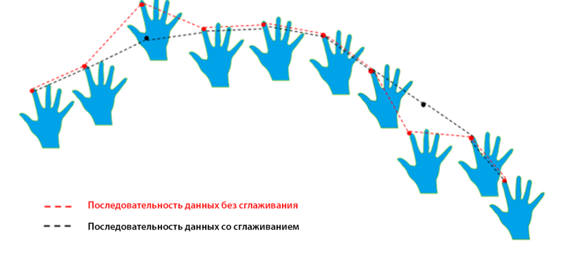
Figure 9. Data with and without smoothing
Another way to detect too fast hand movement is by listing TRACKINGSTATUS_HIGH_SPEED in the PXCMHandData.TrackingStatusType property. When a face is detected, fast movements can lead to loss of tracking. Use PXCMFaceData.AlertData.AlertType - ALERT_FACE_LOST to determine lost tracking. If you are using hand gestures to control the operating system with the Touchless Controller, use the PXC [M] TouchlessController's SetPointerSensitivity and SetScrollSensitivity functions to adjust pointer sensitivity and scrolling.
Bounding box
An effective mechanism to achieve smooth action and interaction with objects is the use of restrictive frameworks. They provide users with a clear visual indication of the source and destination of the object with which the user interacts.
The face and hand tracking modules in the SDK support the PXCMHandData.IHand.QueryBoundingBoxImage API, which returns the location and dimensions of the tracked hand (two-dimensional bounding box) on the depth map. The PXCMFaceData.DetectionData.QueryBoundingRect API returns the bounding box of the detected face. You can also use PXCMHandData.AlertType - ALERT_HAND_OUT_OF_BORDERS to detect the exit of a hand beyond the bounding box.
API references in the SDK documentation
Recommendations for creating user interfaces and using the API for the R200 camera
The R200 camera is built into the tablets and comes in the form of a removable device. It is designed to capture the space around the user. Among the possible scenarios for using the R200 camera, such solutions as augmented reality and shooting of the entire human body should be noted. The surrounding world is in the field of view of this camera, therefore the nature and set of problems for designing user interfaces differ from those described above for the F200 camera. This section describes some of the known user interface problems associated with the Scene Perception module (to be used by developers in augmented reality applications) and with the 3D Scanning module.
Result 1. Understanding the survey shooting space and interaction areas for tablets.
UI usage scenario
As seen in fig. 10, the viewing angles of the R200 camera both vertically and horizontally, as well as its range, are significantly different from those of the F200. The R200 can be used in two different modes: in active mode (when the user moves while shooting a scene) and in passive mode (when the user is working with a still image). When shooting an object or scene, make sure that the object is in the field of view of the camera while the user is shooting it in active mode. Also note that the range of this camera (depending on whether it is used indoors or outdoors) differs from the range of the F200 camera. How do I get these data points at run time to provide the user with visual feedback?
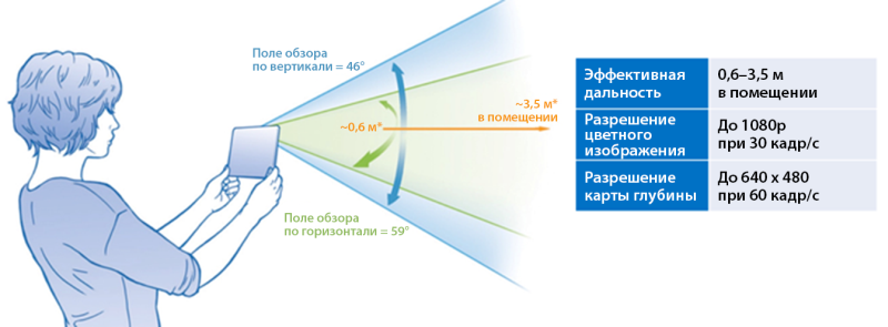
Figure 10. Surround space of the R200 camera
Technical implementation
We have already discussed the QueryColorFieldOfView () API and QueryDepthFieldOfView () above in the section on the F200 camera. These functions do not depend on the device, they can be used for volumetric shooting with the R200 camera. However, to detect the range of the R200 camera, you need to use a specialized API designed only for this device. To obtain such data for the R200 camera, you must use the QueryDSMinMaxZ API, available as part of the PXCCapture interface. It returns the minimum and maximum range of the camera in millimeters.
API references in the SDK documentation
Result 2. Understanding user actions and scene interaction.
User Interface Scenario: Scheduling Considering the Scene and Camera Features
When working with the camera in active mode, be aware of the limitations of the camera. These depths will be less accurate when shooting a scene with very bright areas, with reflective and with black surfaces. Information about when the failure of tracking is possible will help build an effective feedback mechanism into the application to gently remind the user of the necessary actions, rather than shutting down the work with an error.
Technical implementation
Scene Perception and 3D Scanning modules have different requirements, and therefore they use different mechanisms to detect minimum requirements.
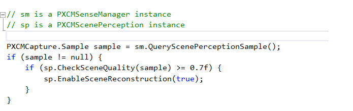
Scene Perception . Always use the CheckSceneQuality API in the PXCScenePerception module to determine if the scene is suitable for tracking. The API returns a value between 0 and 1. The higher the return value, the better the scene to track. This is how the code is implemented.
After the scene quality is deemed satisfactory and tracking begins, you should dynamically check the tracking status using the TrackingAccuracy API in the PXCScenePerception module. This API provides tracking accuracy.
| Name | Description |
|---|---|
| HIGH | High tracking accuracy |
| LOW | Low tracking accuracy |
| MED | Average tracking accuracy |
| FAILED | Tracking failed |
To maximize the quality of the scene data, you can also adjust the voxel resolution (voxel is a unit of resolution for a 3D image). Depending on what the camera is tracking (space-sized room, table surface, or close object), adjust the resolution of the voxels according to the table below for best results.
| Name | Description |
|---|---|
| LOW_RESOLUTION | Low voxel resolution. Use this resolution to track room size (4/256 m). |
| MED_RESOLUTION | The average resolution of voxels. Use this resolution to track the tabletop (2/256 m). |
| HIGH_RESOLUTION | High resolution voxels. Use this permission to track small objects (1/256 m). |
3D Scanning The 3D Scanning algorithm provides the alerts shown in the table below. To obtain this data use PXC3DScan :: AlertEvent .
| Name | Description |
|---|---|
| ALERT_IN_RANGE | The subject is at a suitable distance. |
| ALERT_TOO_CLOSE | The subject is too close to the camera. Ask the user to move the object away from the camera. |
| ALERT_TOO_FAR | The subject is too far away from the camera. Have the user move the object toward the camera. |
| ALERT_TRACKING | The subject is being tracked correctly. |
| ALERT_LOST_TRACKING | The tracking of the object is lost. |
If the application has available camera tracking data and the limitations of the module used, this data can be used to provide visual feedback, clearly telling users how their actions were interpreted by the camera. In case of loss of tracking, you can show how to work with the camera more correctly. Examples of visual feedback are shown here for example only, they must be adapted to the requirements of the application and with the user interface device.
Sample curriculum at startup.
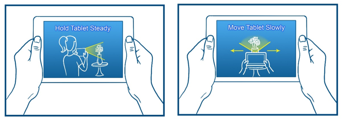
Figure 11. Training
Preview of the captured area or subject.
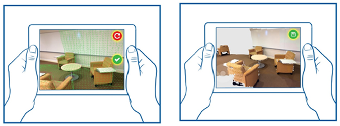
Figure 12. Preview
Hints for the user.
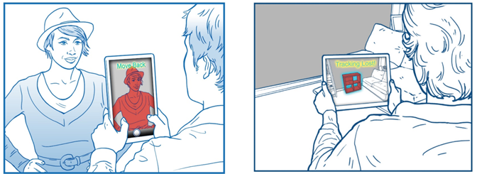
Figure 13. User Tips
Reduced fatigue when the user holds the device in their hands
Most applications will use the device with both active and inactive camera modes. (These two modes differ as follows: the camera works in active mode when the user holds the tablet in hand to view the scene through the camera or to shoot; the camera works in the inactive mode when the user laid down the tablet and works with the contents on the screen, while the camera is turned off). To reduce user fatigue, it is necessary to understand how the user holds and uses the device in each of these modes, and to select the interaction zones accordingly. When using the camera in the active mode, the user gets tired faster, because he keeps the device on weight, as shown in fig. 14.

Figure 14. Use of the device in active and inactive modes
Choosing the right mode for action
The usage mode also directly determines the nature of interaction with the application through the user interface. In active mode, the user holds the device with both hands. Therefore, any visual elements of the application, such as buttons, should be located in easily accessible places on the screen. Studies show that in such cases it is best to use the edges of the screen. Recommended touch zones are shown in Fig. 15. In addition, the touch accuracy is reduced in the asset mode, so the active mode is best suited for short-term shooting.
On the contrary, in inactive mode it is more convenient for the user to work with the device, the user interacts with the interface elements more precisely and can use the application for a long time.
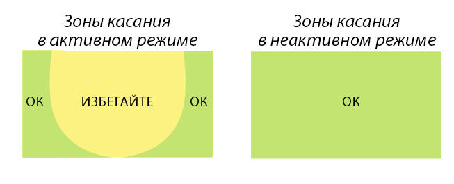
Figure 15. Touch zones in active and inactive modes
API references in the SDK documentation
Conclusion
When developing applications using Intel® RealSense ™ technology, developers should take into account the needs and features of the end users from the earliest stages. The recommendations provided in this article will serve as the basis for solving some important problems of user interfaces and for implementing the necessary components in code using the SDK.
Additional materials
Source: https://habr.com/ru/post/276435/
All Articles