Alteration of RC-cars in a smart machine using Arduino
In many projects at Arduino it is proposed to do the same that is sold in stores, but with much higher labor and material costs. Today's project is not the same, smart cars are sold in stores, but they cost on average 5 times more expensive than RC cars. Therefore, I decided to share how you can transform almost any RC machine into a modern car with the prefix "smart" with the help of Arduino. Here is a demo video of what came out:
So, I decided to redo the standard RC-machine, bought in a toy store for about 500 rubles.
')

Alteration can be done in two main ways:
1. Connect arduino to the remote control from the machine
2. "implant" arduino inside the machine itself
I decided to try both ways, but today I’ll tell you only about the first one, because it is somewhat simpler, but it’s better to start with simple ones.
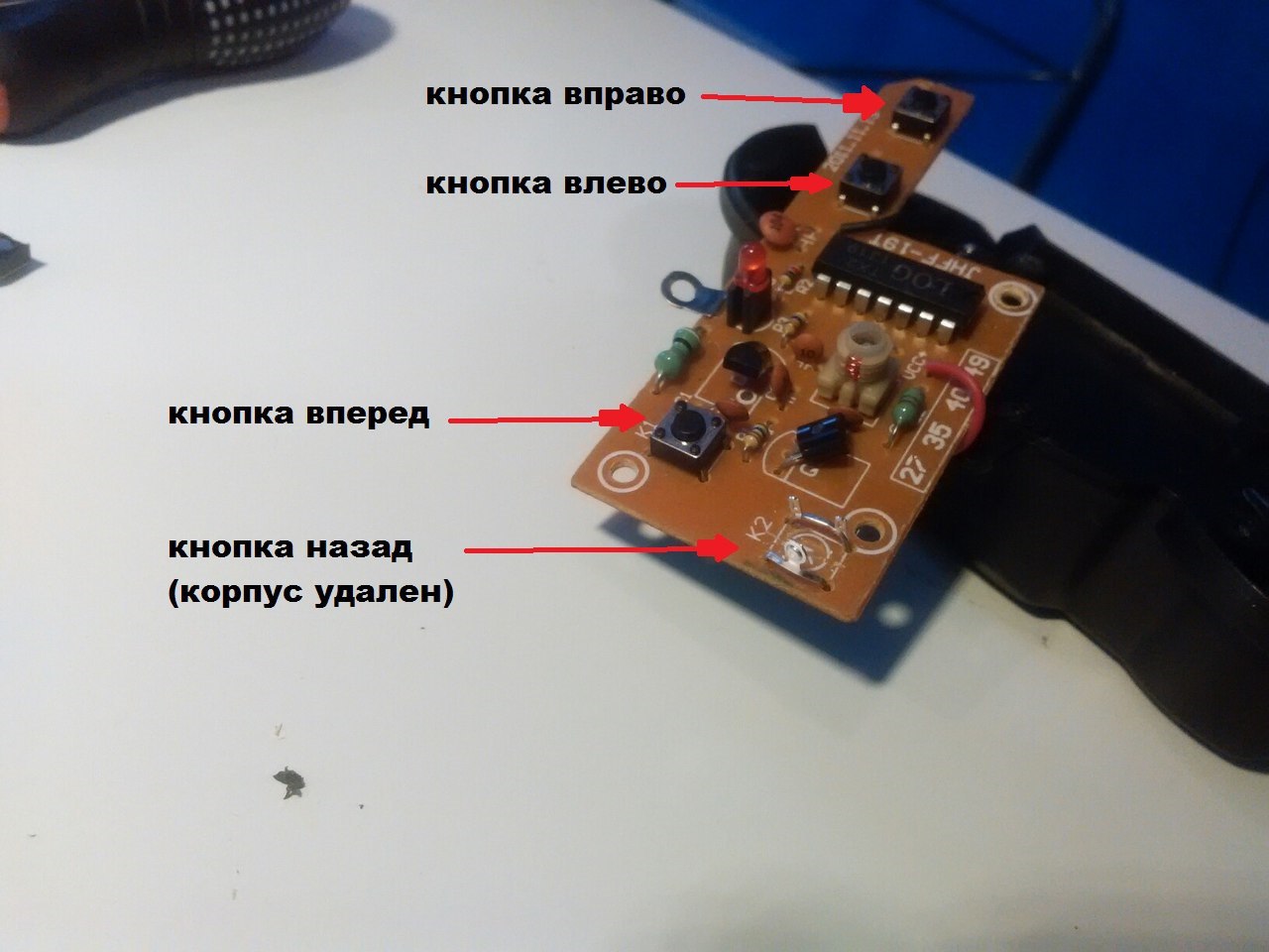
To connect to the remote control, you must first disassemble and remove those 4 buttons that are responsible for moving back and forth and turning left and right. You can unsolder them, and you can just break the body of the buttons, leaving only the contacts.
Instead of four buttons, we connect a four-channel relay block according to the scheme:
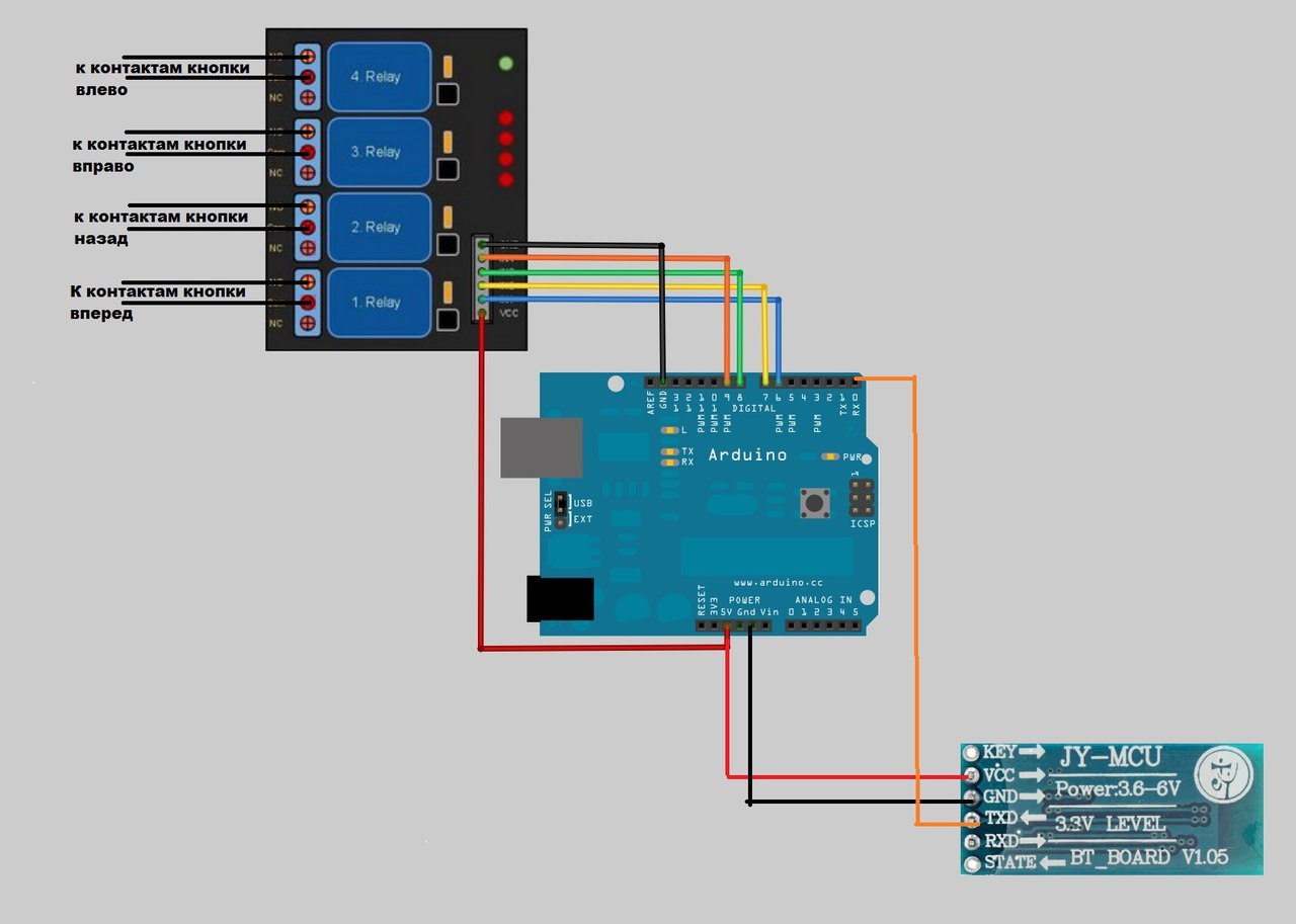
The relay unit is connected to the Arduino, and it will already receive signals from the smartphone via the Bluetooth module. Sketch for Arduino
Now you need to make a simple application to manage all this like this:

The application I made in the visual development environment of Android applications App Inventor 2.
It looks like the application:
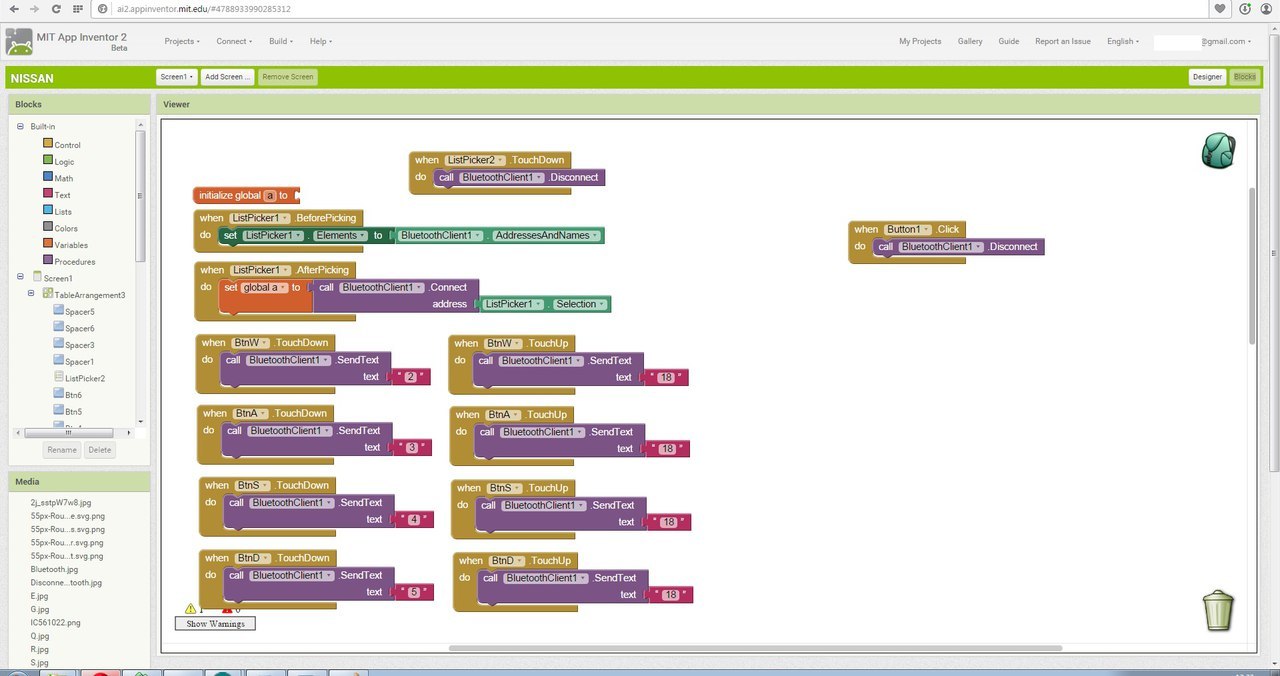
The logic of the application is very simple: when you touch the button with your finger, it sends a signal to close the corresponding relay to Arduino. When the button is released, the command is sent to open all relays. You can download the application here , the source code here , but if someone has half an hour or an hour of extra time, then you can make such an application from scratch. On this topic, I shot a separate video where I tell in detail what and how to do for those who are faced with this development environment for the first time.
Well, at the end of the photo of how this control scheme looks. I didn’t pack all this in a box, because the plans are the introduction of arduino directly into the body of this machine.

PS Collection of more than 100 training materials on arduino for beginners and pros here
PPS Online course on arduino to giktaimes here.
So, I decided to redo the standard RC-machine, bought in a toy store for about 500 rubles.
')
Alteration can be done in two main ways:
1. Connect arduino to the remote control from the machine
2. "implant" arduino inside the machine itself
I decided to try both ways, but today I’ll tell you only about the first one, because it is somewhat simpler, but it’s better to start with simple ones.
To connect to the remote control, you must first disassemble and remove those 4 buttons that are responsible for moving back and forth and turning left and right. You can unsolder them, and you can just break the body of the buttons, leaving only the contacts.
Instead of four buttons, we connect a four-channel relay block according to the scheme:
The relay unit is connected to the Arduino, and it will already receive signals from the smartphone via the Bluetooth module. Sketch for Arduino
here
unsigned long incomingByte;
int LED2 = 6;
int LED3 = 7;
int LED4 = 8;
int LED5 = 9;
void setup () {
Serial.begin (9600);
Serial.setTimeout (4);
pinMode (LED2, OUTPUT);
pinMode (LED3, OUTPUT);
pinMode (LED4, OUTPUT);
pinMode (LED5, OUTPUT);
}
void loop () {
if (Serial.available ()> 0) {
incomingByte = Serial.parseInt ();
if (incomingByte == 2) {digitalWrite (LED2, LOW); }
if (incomingByte == 3) {digitalWrite (LED3, LOW); digitalWrite (LED2, LOW); }
if (incomingByte == 4) {digitalWrite (LED4, LOW); }
if (incomingByte == 5) {digitalWrite (LED5, LOW); digitalWrite (LED2, LOW);}
if (incomingByte == 18) {digitalWrite (LED2, HIGH); }
if (incomingByte == 18) {digitalWrite (LED3, HIGH); }
if (incomingByte == 18) {digitalWrite (LED4, HIGH); }
if (incomingByte == 18) {digitalWrite (LED5, HIGH); }
}
}
Now you need to make a simple application to manage all this like this:
The application I made in the visual development environment of Android applications App Inventor 2.
It looks like the application:
The logic of the application is very simple: when you touch the button with your finger, it sends a signal to close the corresponding relay to Arduino. When the button is released, the command is sent to open all relays. You can download the application here , the source code here , but if someone has half an hour or an hour of extra time, then you can make such an application from scratch. On this topic, I shot a separate video where I tell in detail what and how to do for those who are faced with this development environment for the first time.
Well, at the end of the photo of how this control scheme looks. I didn’t pack all this in a box, because the plans are the introduction of arduino directly into the body of this machine.
PS Collection of more than 100 training materials on arduino for beginners and pros here
PPS Online course on arduino to giktaimes here.
Source: https://habr.com/ru/post/275979/
All Articles