Experience home rover
Hi Habr! I work as an RnD artist in the Minsk Wargaming Development Center. And in my free time I give free rein to my engineering fantasy. In this article I want to share my experience of home mars rokhodostroeniya.
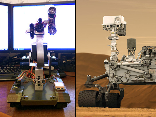
It all started with the fact that I wanted to feel what it was like to operate the rover, located in dozens of light minutes. Of course, there is no access to a real rover, so I built my own. The main condition I was going to meet is the simulation of a time lag in management. Effort spent mass, but the desired result was achieved.
I will not dwell on my research in detail, but will immediately describe the final design. If you are wondering why I came to these solutions and components (or can offer better options), then you are welcome in the comments.
Hardware
First of all, the platform was acquired - a radio-controlled tank Abrams M1A2, the contents of which (with the exception of engines) were mercilessly gutted:

')
Next, I started searching for a power source. Unfortunately, Plutonium-238 could not be found for an improvised RTG, so I had to use an alternative. A worthy replacement was the battery of 16 NCR18650B batteries (3400 mA) with a charge / discharge controller. Settlement capacity - 27 A / h at a voltage of 7.2 V:

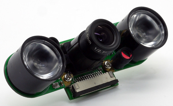
The brain of the rover was the Raspberry Pi 2. A loop (extended and reinforced with adhesive tape) is connected to a camera without an IR filter, with infrared illumination:
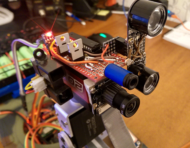
The backlight consumes a lot of energy, so it turns on only during shooting at the light level below the set threshold. Also, only for the time of measurement, the optical range finder is turned on. Switching on and off takes place with the help of 40-ampere mosphets (there were no other keys in stock), controlled by an Atmega328 microcontroller with minimal strapping. A range finder and a photoresistor are connected to the same controller. For the latter, I selected an approximation function for an industrial light meter taken at work (there we use it for lighting validation). I also used the non-contact temperature sensor MLX90614. All this strapping was assembled on a breadboard and bolted to the servo motors of head rotation. The head module is connected to the Raspberry with just four wires - power and I2C bus.
To control the servos, I used the specialized PCA9685 I2C controller with 16 PWM outputs. At first I tried Arduino, but the library for servo drives was implemented there programmatically. Because of this, spontaneous jerks and twitches occurred during the operation of the controller with I2C. Once the rover even began to thresh the camera on the table. After replacing the Arduino with the PCA9685, all movements became smooth
To control the engines, I used a slightly modified Dual Channel H-Bridge Motor Shield .

By default, control requires seven lines, two of which are PWM. I threw away the input logic, connecting to the inputs of the drivers on the line. It turned out five control lines. But now it has become necessary for four of them to be controlled via PWM. I tried to use the remaining PCA9685 lines, but it turned out that the PWM frequency on all channels should be one, and 50 hertz to control the servomotors did not suit me at all. Raspberry has only one full-fledged PWM, and did not want to get involved with software. As a result, I decided to use an additional controller, which at the same time measures the voltage of the battery. The result was I2C Motorshield:
In addition, I installed encoders from mice with rubber wheels from them, which track speed and distance when moving. Encoders are connected to the Malinka via RC filters and cause interrupts in the handler when triggered. The use of simple filters almost eliminated the contact bounce, and the remaining random responses were simply cut off in the code. The speed is measured by the time interval between interruptions, and averaged over several measurements.
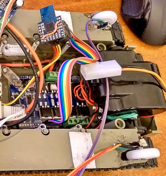
To power the rover, two down stabilizers are used - separately for Raspberry and electronics, and separately for servo drives. The insides of the rover look like this:

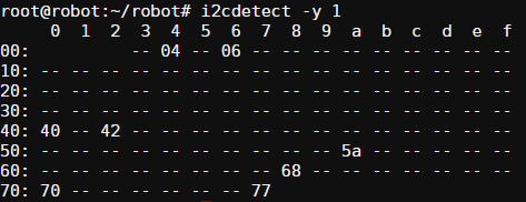
Humidity and pressure sensors, as well as GPS, I rendered on the "armor". GPS is connected to the Raspberry native serial port. In the end, I got this “zoo” of I2C devices:
Initially, the Arduino worked as a control center with a radio module connected to a PC. But the decision was not entirely authentic, so I replaced it with another Raspberry Pi 2, managed via SSH. At the same time, this allowed the rover to be controlled not from home (if you know what I mean). Data exchange with the rover goes through the modules nrf24L01 PA.

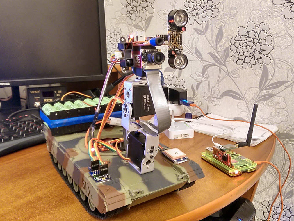
The final photo of the rover:
Software
To work with hardware, I compiled and installed the BCM2835, WiringPi, NRF24, and OpenCV libraries. There were great concerns about the latter, but surprisingly, everything went smoothly. Although the assembly took more than three hours. OpenCV was needed to correct the strong distortion of the camera (for this I calibrated the camera), to draw the GUI over the images and create a primitive panorama:

I had to tinker with libraries for I2C sensors. In the end, I realized that each sensor prefers its own bus frequency. Most of the sensor code had to be rewritten under the BCM2835 library - here the bus frequency can be adjusted. Not without incidents. It turned out that a nine-axis gyro magnetometer is a separate device with its address. With its program connection to the common bus, for some reason he cut down the humidity sensor, although they had different addresses. Therefore, the magnetometer is programmed to the bus just before measuring.
Updating the accelerometer data for the MadgwickAHRS filter is necessary with equal intervals of time, so I rendered its code into a separate stream. To avoid bus access conflicts, added a mutex for I2C. By the way, MadgwickAHRS is a very handy thing - we feed it with raw data, and at the output we get a ready filtered quaternion of rover rotation in space. In order for the data not to float much, a calibrated gyroscope is needed. It also allows you to get the roll and pitch of the rover and rotate at a given angle.
To implement a custom radio delay, I used queues from the structures (32 bytes of a packet and a time stamp), as well as two separate streams. One communicates directly with the radio module, and the second handles data management. Again, there are mutexes to protect against conflicts. The exchange protocol is simple to disgrace - accept / send a string or file. Due to this, it is possible to transfer the compiled program from the control center to the rover - as a result, it was useful for editing bugs during the mission.
I drive engines through PID-regulators, taking into account data from encoders. I spent several days on adjusting the coefficients of the regulators, taking dozens and even hundreds of graphs and adjusting the parameters. But in the end I achieved smooth and precise work.
There were some problems with data loss on the I2C bus between raspberries and microcontrollers. Decided to use checksums.
I wrote a parser for the GPS module, since NMEA 0183 protocol is not difficult. The parser runs in a separate thread and processes incoming information character by character.
He taught the rover to do heat maps using mlx90614 (the same view from the balcony):

Mission 1: test at home
Initially, I planned to leave the countryside and run the rover in the countryside. But due to adverse weather conditions (half a meter of snow cover), it was decided to launch it right in the apartment.
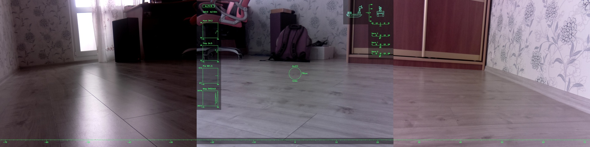
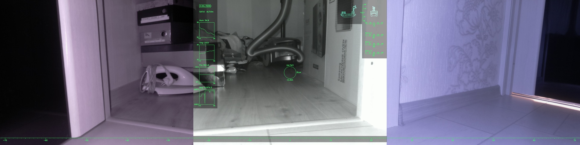
So, the rover was activated before going to work. I remotely contacted the control center and successfully connected to the rover. The signal delay is set to two minutes. Soon received the first panorama (clickable):
In general, the rover control log looked like this:
Suddenly there was a bug in the code - the rover did not wait for the end of the movement commands. I had to edit, collect and send him the fixed firmware. And so the rover is sent to meet the unknown:
But another problem surfaced - information coming over the radio channel suddenly began to deteriorate. An example (check for checksum is disabled here, otherwise the files would not be accepted):

A quick review revealed that the SPI bus in the control center was to blame. By reducing its frequency by half, the problem was solved. At the same time I lowered the frequency of the bus for the rover and filled it with a new firmware.
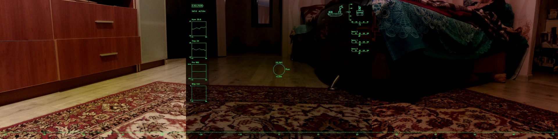
So, the mission continued. First heat scan:

In general, remotely controlling the rover with a significant delay was very exciting. That's just the speed of advancement is low. For example, drove into the pantry, the rover for an hour trying to get out. As it later became clear, I didn’t calculate the distance and hooked the head module to the vacuum cleaner hose:

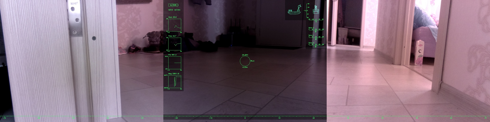
More pictures: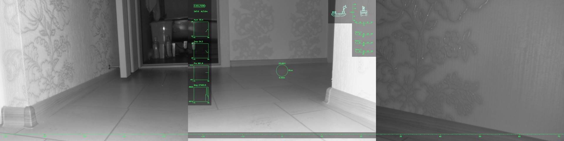


When the radio module failed in the control center, the mission had to be curtailed, since At the software level, the problem could not be solved (the connectors failed).
Spring is coming! Therefore, I plan in the near future to fix all the bugs and send the rover to the street.
If you can share a useful experience or just want to ask questions - write comments.
All sources here github.com/DIMOSUS/Rover
Source: https://habr.com/ru/post/275953/
All Articles