Clock on FPGA Lattice
 Some time ago, DmitrySpb79 wrote articles on the creation of electronic watches. In them, he considered the sources of exact time , as well as the element base for the creation of electronic clocks . Arduino, STM, Raspberry PI, ESP8266 were mentioned, but FPGAs were completely forgotten .
Let's fill this little gap. We find out how easy it is to make a clock on the FPGA and what hardware resources will be required for this. Besides, they gave me a FPGA chip of a very small volume - 64 macro cells. This is the Lattice FPGA LC4064v with which I have never worked before. I think it will be interesting!
Goals:
')
- try to fit the logic of the clock in a small FPGA (64 macro cells);
- master the static or dynamic LED display on the FPGA for time display;
- collect a bunch of rakes related to the independent development of schemes and get a new experience;
- master the new development and programming environment for FPGAs from Lattice, assess the complexity of the transition
I expect several very pleasant evenings dedicated to the development of FPGA!
Manufacturer FPGA Lattice?
 Lattice Semiconductor Corporation is an American chip maker. The company is located in Oregon and produces high-performance FPGAs. There is information that microcircuits are popular in industrial developments because of the openness of documentation and protocols. A wide list of products and their appointments suggests that they make a series of FPGAs for automation, automotive, creating compact, portable, cost-effective devices. Also, there are FPGA series of large volumes (up to 100k and more macrocells).
Where to find FPGA Lattice?
 Unfortunately, I have not yet been able to find a store where I could buy FPGAs with a volume of 1–4 thousand macrocells and a price of one or two thousand rubles. However, I found a fee to meet my requirements - Programmable Logic IC Development Tools MachXO3LF StarterKit . The number of cells is 6900, there is already a programmer ( FTDI ) on the board, 8 LEDs . The price of $ 25, however, the cost of delivery, at checkout in the Lattice Store, was $ 45. Well, there will be money - I will search on digikey or mouser and at the same time master them. However, there was still a purchase option in the Motherland, in the Elitan store, at a price of 2992 rubles. On Ebay / Aliexpress, the choice is not big yet, but we managed to find a chip without a 5,000-cell board - LFXP2-5E-5QN208C .
When disassembling old electronics, CPLD of small sizes (32, 64 cells) are periodically caught. One such microcircuit was presented to me by my friend. FPGA chip LC4064V ( pdf ) - a representative of the ispMACH 4000V / B / C / Z Family family . My version works on 3.3V voltage, at frequencies up to 400 MHz! The TQFP package contains as many as 32 I / O lines, of which two are used for clock inputs. The lines are tolerant to 5 V in the modes LVCMOS3.3, LVTTL and PCI. All conclusions can be "pulled" pull-up, pull-down, or can hang in the air. Also, you can work in open-drain mode.
Lattice Development Environment
For small FPGAs that need LC4064v is needed: ispLEVER Classic .
For firmware, you need to install: Diamond Programmer .
For larger FPGAs: Lattice Diamond .
To activate the programs, you need to register on e site , specify your MAC address and download license keys.
To create a general idea of how to develop projects in the Lattice Diamond environment, I recommend reading this video .
How to "flash" Lattice?
LPT programmers are almost gone. And there is no time and desire to assemble a programmer (there is a desire to do a project). As in the case of Altera, I decided to find and buy a ready-made Chinese clone of the programmer, on Ebay or Aliexpress sites. However, if the programmer for Altera is within 300 rubles , then for Lattice the price is already about 2000 rubles . For the seemingly identical products, differing only by the sticker. But if you carefully search, you can find it cheaper - 1300 rubles ! I take two at once: myself and my friend. Upon arrival, one programmer refused to work . He began to communicate with the seller, he assured that they all checked. As a result, I repaired it myself by disappearing the ground on the USB connector.
Compared with the programmer for Altera, to make sure that they are different, and not "only the USB ID is different."
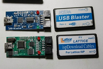
A few more photos: 1 , 2 , 3 . Chip is really more, so it is quite obvious that the programmer turns out more expensive.
To check the chip in haste I make a board with LEDs and a button. I solder the microcircuit on the adapter board.

As a generator, I did not find anything simpler than the FPGA of Altera Cyclone :) I shared the clock frequency of 50 MHz to 2 Hz and brought it back. This signal applied to the clock input LC4064v. Made the simplest 4-bit counter, and brought his bits out and connected to the LEDs.
I'm flashing it - it works!
Now, when it became clear that the FPGA works and is programmable, you can invent a
What problem to solve?
In fact, the idea to make a watch did not come immediately. The number of cells, equal to 64, makes you think about the task that you can assign them. I remember the old days when there was a strictly defined MK available, which I could program, and I tried to fit the solved problem into it. Programming the FPGA assumes the opposite: solving the problem and choosing the FPGA of the desired size based on the results of the synthesis. But here we turn everything upside down, and limit ourselves to size. This will force us to work hard both in the choice of the task and in its implementation. Some kind of extreme programming in limited conditions.
What to do? Electronic synthesizer? Not enough cells: only a MIDI command receiver takes more than one hundred. Need something simple! For example, decoder audio I2S flow and output it through the DAC on the resistors? As it is very specific, simple and not very spectacular. There are many lines - you can hang seven-segment indicators (7x4 = 28 even statically!). And what to portray? You can make either a frequency counter (a great option, because the chip works right up to 400 MHz) or a clock. It was decided to choose a watch.
Parts for assembling watches
For hours we will need a seven-segment indicator of four digits. At first I wanted to buy a new indicator in the store, and then I remembered that I already had a time indicator, which has been in the box for about ten years already. I once gave it a long time ago to regenerator from the RadioKot forum. The scheme of turning on my indicator has the following scary look:

As part of ridding the boxes of stale components, as well as bullying FPGAs (and ourselves), it was decided to use this seemingly incomprehensible indicator. In fact, everything is quite simple: from above we apply the control voltage to the indicators. As a rule, one wire goes to two segments at once. And which of the two segments will work is determined by the bus that we connected to the common wire at the moment. The scheme, in general, corresponds to the classical dynamic indication scheme with the difference that we have only two indicators. To test the operation of all indicators, I brought a logical unit to all outputs, and I brought the signal to transistors in turn.
According to the test results, it turned out that we, in principle, can display a number on any indicator. However, in the leftmost indicator is missing one segment. This will not allow to display all possible digits on it, but the most important thing is the number "zero". This fact is confirmed by this picture . Therefore, zero in dozens of hours will be extinguished.
We also need a "clock generator" - a generator at a frequency of 32768 Hz. Why such a frequency? Because if you take a 15-bit binary counter and apply this frequency to it, then we will get 1 Hz (2 ^ 15 = 32768) at the output. That is an interval of one second. I want to note another important point in choosing the frequency of the generator. In order to divide the frequency by 32768, a 15-bit binary counter is required, and it will at least take 15 cells in the FPGA, which will immediately take up almost a quarter of the resources. The counter for the 50 MHz oscillator will require 30 bits to divide by the second interval. At such costs, the cells on the logic of the clock may not be enough.
While there is no quartz clock, again Altera Cyclone will act as a frequency generator, in which I integerly divided the frequency 50 MHz to 32768 Hz.
For frequency division, I use my Verilog module. It is very simple to work with it: at clk we give the original frequency, from s_out we get the result. The division factor set parameter DIV. In my case, 50000000 Hz is the input clock frequency, and 32768 Hz is the frequency that needs to be received.
frqdivmod #(.DIV(50000000/32768)) divider(.clk(clk50M), .s_out(clk32768)); Code module frequency divider by integer (Verilog)
module frqdivmod(clk, s_out); parameter DIV=2; // calculated parameters parameter WITH = ($clog2(DIV)>0) ? $clog2(DIV) : 1; input wire clk; output wire s_out; reg clk_n; reg [(WITH-1):0] pos_cnt; reg [(WITH-1):0] neg_cnt; wire [(WITH-1):0] div_value = DIV[(WITH-1):0]; initial begin clk_n <= 1'b0; pos_cnt <= {(WITH){1'b0}}; neg_cnt <= {(WITH){1'b0}}; end assign s_out = (DIV==1) ? clk : clk_n; always @ (posedge clk) begin pos_cnt <= (pos_cnt + 1'b1) % div_value; end always @ (negedge clk) begin neg_cnt <= (neg_cnt + 1'b1) % div_value; end always @(clk, pos_cnt, neg_cnt) begin //pos_cnt in sens list addd for resolve warning "variable is read inside the Always Construct but isn't in the Always Construct's Event Control" if ((DIV%2) == 1'b0) begin clk_n <= ( pos_cnt >= (DIV/2)) ? 1'b1 : 1'b0; end else begin clk_n <= (( pos_cnt > (DIV/2)) || ( neg_cnt > (DIV/2))) ? 1'b1 : 1'b0; end end endmodule We set hardware logic
The first iteration of creating a clock is the creation of a binary counter circuit with asynchronous reset (click on the picture to open the circuit on the site http://www.falstad.com/ where you can adjust it as you like)

When the counter reaches the value "10" (b1010) - we must reset it. The same signal will be used as a clock for the next digit counter.
RC string is used to increase the period of the signal to reach "10". If this signal is too short, then some triggers may not have time to reset, or change their value. But the use of asynchronous reset in the FPGA can lead to a number of problems. In order to increase the signal period, we use analog circuitry, although we are developing a digital circuit. If we want to apply this approach in the FPGA, then we will need to output this signal to the outside of the chip - to the external output, install a chain there, and then send it back - to another input of the FPGA.
Verilog module defining an asynchronous reset counter
// counter module cntr #(parameter width=4) (clk, res, out); input wire clk, res; output reg [width-1:0] out; initial out <= {width{1'b0}}; always @(posedge clk or posedge res) begin if (res) begin out <= 0; end else begin out <= out + 1'b1; end end endmodule As an experiment, I still made a watch on counters with asynchronous reset. At the same time, I did not output or use any RC chains. My goal was to find out if you really shouldn’t use asynchronous logic, or "oh well and so it’s okay." Up to some stage the clock regularly counted time
But at that moment, when I decided to add a flashing second in the clock, everything suddenly broke down.
When developing on FPGA it is strongly recommended to use synchronous logic. In the case of a clock and a counter, the current value of the counter must be stored in a register, and the next value of the register we must calculate the combinational circuit. The next value will be unequivocally calculated (we hope so) before the next clock, but will be loaded into the register on the front of the clock pulse. That is, no "needles" of the dump will not slip. Based on the current values of the registers, we always uniquely determine the value on the next clock cycle.
reg [3:0] s;// 0..9 - 4bit -- // wire s_cy = (s == 4'd9); // : wire [3:0] next_s = (s_cy) ? 4'd0 : (s + 1'b1); // +1, 0, 9 // always @(posedge clk1Hz) begin s <= next_s; end To output the register value to a seven-segment indicator, we need a converter module from binary to seven-segment code:
Verilog module bcd2seg0_9
//bin to 7seg module bcd2seg0_9(sin, sout); input wire [3:0] sin; output wire [6:0] sout; reg [6:0] SEG_buf; always @ (sin) begin case(sin) 4'h0: SEG_buf <= 7'b0111111; 4'h1: SEG_buf <= 7'b0000110; 4'h2: SEG_buf <= 7'b1011011; 4'h3: SEG_buf <= 7'b1001111; 4'h4: SEG_buf <= 7'b1100110; 4'h5: SEG_buf <= 7'b1101101; 4'h6: SEG_buf <= 7'b1111101; 4'h7: SEG_buf <= 7'b0000111; 4'h8: SEG_buf <= 7'b1111111; 4'h9: SEG_buf <= 7'b1101111; default: SEG_buf <= 7'b0000000; endcase end assign sout = SEG_buf; endmodule To save resources, we describe options only for numbers from 0 to 9. For the experiment, try an alternative converter module:
Verilog module bcd2seg0_9 (2)
//bin to 7seg module bcd2seg(sin, sout); input wire [3:0] sin; output wire [6:0] sout; assign sout = (sin==4'h0) ? 7'b0111111 : (sin==4'h1) ? 7'b0000110 : (sin==4'h2) ? 7'b1011011 : (sin==4'h3) ? 7'b1001111 : (sin==4'h4) ? 7'b1100110 : (sin==4'h5) ? 7'b1101101 : (sin==4'h6) ? 7'b1111101 : (sin==4'h7) ? 7'b0000111 : (sin==4'h8) ? 7'b1111111 : (sin==4'h9) ? 7'b1101111 : 7'b0000000; endmodule But the amount of resources expended has not changed. We are happy for a smart synthesizer.
Then simply create registers for seconds (units, tens), minutes (units, tens), hours (units, tens). For each set the calculation of the next value. But we make the change in the seconds value at every second pulse, while the change in the value of tens of seconds only happens when the units overflow. Accordingly, units of minutes only change when tens and units of seconds are overflowed. And so on.
At the same time, the synthesis showed that everything is fine, but the device cells are no longer enough. Oops. In order to rectify the situation, it was decided to simplify the second register. It is not output anyway, so we change two binary decimal counters by one binary from 0 to 59. And running a little ahead, I made it one bit more, but I reduced the counter of the common clock quartz frequency divider. Therefore, the count goes from 0 to 119, but with a frequency of 2 Hz (see below, part about setting the time).
//clk - general clock 32768 reg [13:0] clk_div; initial clk_div <= 14'd0; //?? Lattice always @(posedge clk) clk_div <= clk_div + 1'b1; // , , reg [6:0] sec;// 0..119 reg [3:0] m ;// 0..9 reg [3:0] mm ;// 0..5 reg [3:0] h ;// 0..9 reg [3:0] hh ;// 0..2 // wire sec_cy = (sec == 7'd119); wire [6:0] next_sec = (sec_cy) ? 7'd0 : (sec + 1'b1); wire m_cy = (m == 4'd9);// && sec_cy; wire [3:0] next_m = (m_cy) ? 4'd0 : (m + 1'b1);//(m_cy) ? 4'd0 : (m + ss_cy); wire mm_cy = ((mm == 3'd5) &&(m == 4'd9)); wire [2:0] next_mm = (mm_cy) ? 3'd0 : (mm + 1'b1); wire h_cy = (h == 4'd9)||((hh == 4'd2) && (h == 4'd3)); wire [3:0] next_h = (h_cy) ? 4'd0 : (h + 1'b1); wire hh_cy = ((hh == 2'd2) && (h == 4'd3)); wire [1:0] next_hh = (hh_cy) ? 2'd0 : (hh + 1'b1); // wire timer_clk = clk_div[13]; always @(posedge timer_clk) begin sec <= next_sec; m <= ( sec_cy) ? next_m : m; mm <= ( m_cy&&sec_cy) ? next_mm : mm; h <= ( mm_cy&&m_cy&&sec_cy) ? next_h : h; hh <= (h_cy&mm_cy&&m_cy&&sec_cy) ? next_hh : hh; end Conclusion on seven-segment indicators
Each register HH: MM we output to seven-segment indicators. But before that, we transform it into a seven-segment code.
// wire [6:0] s_m; wire [6:0] s_mm; wire [6:0] s_h; wire [6:0] s_hh; // bcd2seg0_9 sseg_m( .sin(m), .sout(s_m)); bcd2seg0_5 sseg_mm(.sin(mm), .sout(s_mm)); bcd2seg0_9 sseg_h( .sin(h), .sout(s_h)); bcd2seg0_2 sseg_hh(.sin(hh), .sout(s_hh)); But we have a dynamic display. Moreover, during the output, not separate seven-segment blocks are switched, but separate elements of indicators. Therefore, let’s go down to the level of each indicator element:
// wire a1,b1,c1,d1,e1,f1,g1; wire a2,b2,c2,d2,e2,f2,g2; wire a3,b3,c3,d3,e3,f3,g3; wire a4,b4,c4,d4,e4,f4,g4; // assign {g4, f4, e4, d4, c4, b4, a4} = s_m; assign {g3, f3, e3, d3, c3, b3, a3} = s_mm; assign {g2, f2, e2, d2, c2, b2, a2} = s_h; assign {g1, f1, e1, d1, c1, b1, a1} = s_hh; Next, based on the indicator scheme, we understand that there are two lines on the minus. We will switch them in turn:
wire led_line1 = (clk_div[7]); //8- 32768 wire led_line2 = (~led_gnd1);// 256 We assign to the combined lines of the segments, the corresponding values, depending on which line is currently active:
wire h_show = !(hh==0); // assign led6 = (led_line1&&(b1&&h_show)) || (led_line2&&(b1&&h_show)); // b1 assign led7 = (led_line1&&(a1&&h_show)) || (led_line2&&(g1&&h_show)); // a1/g1 assign led8 = (led_line1&&(d1&&h_show)) || (led_line2&&(e1&&h_show)); // d1/e1 assign led9 = (led_line1&&e2) || (led_line2&&(c1&&h_show)); // e2/c1 assign led10 = (led_line1&&g2) || (led_line2&&b2); // g2/b2 assign led12 = (led_line1&&d2) || (led_line2&&c2); // d2/c2 assign led13 = (led_line1&&f2) || (led_line2&&a2); // f2/a2 assign led15 = (led_line1&&a3) || (led_line2&&f3); // a3/f3 assign led16 = (led_line1&&b3) || (led_line2&&g3); // b3/g3 assign led17 = (led_line1&&c3) || (led_line2&&d3); // c3/d3 assign led18 = (led_line1&&e4) || ((led_line2)&&e3); // e3/e4 !! assign led19 = (led_line1&&g4) || ((led_line2)&&b4); // g4/b4 assign led20 = (led_line1&&d4) || ((led_line2)&&c4); // d4/c4 assign led21 = (led_line1&&f4) || ((led_line2)&&a4); // f4/a4 Fight for resources
And here it turns out that there are not enough resources again! In the process of fighting for resources, the following steps were taken:
Altered the encoder from bcd to a seven-segment code. Normal encoder converts numbers from 0 to 15 into hexadecimal format. The clock uses a decimal system for display, so only numbers from 0 to 9 were left in the encoder, that is, the input is 4 bits and the output of 10 seven-bit words. But for tens of minutes (from 0 to 5), a 3-bit encoder is sufficient. That is, 6 options. A similar picture for dozens of hours. Only there are generally 3 digits - from 0 to 2. And this is already 2 bits for the input of the encoder and only 3 options for the output. All of this probably should have reduced the complexity of the synthesis. So it happened! The number of cells used decreased from 63 to 59.
Reduced the digit capacity of the registers of tens of minutes and hours. This will reduce the number of cells by the number of bits, plus it will simplify the schemes of adders.
reg [6:0] sec;// 0..119 - 7bit reg [3:0] m ;// 0..9 - 4bit reg [2:0] mm ;// 0..5 - 3bit reg [3:0] h ;// 0..9 - 4bit reg [1:0] hh ;// 0..2 - 2bit In total, at the start of the optimization, 63 out of 64 cells were occupied, which called into question the possibility of implementing not only possible additional functions, but also basic ones (such as setting the time). Now 56 macrocells are occupied and 8 are free. The percentage was 98%, it was 87%. For such a small volume it is very good: about 10%!
Time setting
Now that the resources have become easier, let's set the time. It was decided to make 3 buttons: "hours", "minutes", "seconds". When you press and hold the "clock" button, their value should increase. The same conditions for the "minutes" button. It is easy to do this: we simply allow the new value to be written to the register at each tick if the button is pressed (and not only when the low-order overflows).
When you press the "seconds" button - another logic: the second counter should be reset and the seconds count should be stopped.
In order to make the time setting more comfortable, the speed of the increase had to be increased, and for this the frequency of the final clock generator was chosen not 1 Hz, but 2 Hz (I wrote about this above). It also saved one cell on a frequency divider, which took one bit less.
input wire btn_HH, btn_MM, btn_SS; // , , wire timer_clk = clk_div[13]; always @(posedge timer_clk) begin sec <= (btn_SS) ? 7'd0 : next_sec; //reset seconds m <= ( sec_cy)||(btn_MM) ? next_m : m; mm <= ( m_cy&&sec_cy)||(btn_MM&&m_cy) ? next_mm : mm; h <= ( mm_cy&&m_cy&&sec_cy)||(btn_HH) ? next_h : h; hh <= (h_cy&mm_cy&&m_cy&&sec_cy)||(btn_HH&&h_cy) ? next_hh : hh; end As you can see, twice a second, we check for an overflow signal or a sign of pressing a button. In both cases, hours or minutes increase. And the seconds value is assigned a zero, while the "seconds" button is held down.
Second indicator
For the second indicator, we no longer have any bits from the register of the frequency divider 32768. Because the minimum frequency there is 2 Hz, and it is necessary to flash once a second. But twice a second, the binary counter of seconds increases. So just take the zero bit from this counter:
assign led_second_tick = sec[0]; Energy consumption and energy saving
The release of cells allowed us to add functionality. One idea is to make a power supply with a backup battery. In the presence of the main power supply, the watch can work in full mode, and in case of switching to backup power supply, it can go into the economy mode: turn off the display and only do time counting.
In order to determine the feasibility of this functionality, you need to determine the current in the normal mode and the current that the device will consume in the power saving mode. You can roughly calculate that with a current of approximately 10 mA per segment and no more than 12 simultaneously operating segments, we only get from the display - 120 mA. Plus FPGA itself consumes energy. According to the documentation - it should be about 10 mA.
Measurements indicate that the entire device consumes 125 mA. This is close to the calculations. I add additional conditions to logic and one more input signal. This is a signal to put the device into an economical mode. We will take the control signal from the power source, from the part of the circuit that receives energy from the network. That the user saw that the device works, being in the economical mode, we will add a blinking second LED. The frequency will be the same, but the filling is not 50%, as in normal mode, but we will make a very short flash. To do this, take part of the bits from the counter-frequency divider. On implementation of this logic only one cell left.
input wire btn_SAFE; // wire SAFE_MODE = ~btn_SAFE; // 1 , , // wire led_line1 = (clk_div[7])&&(SAFE_MODE==0); wire led_line2 = (~led_gnd1) &&(SAFE_MODE==0); // assign led_second_tick = (sec[0]&&(!SAFE_MODE))||(sec[0]&&(clk_div[13:6]==10'd0)&&(SAFE_MODE)); The current in power saving mode was 18.5 mA. In principle, it is not so little. However, if you find an applied FPGA on the manufacturer's website, then it is classified there as "architectures to offer a SuperFast ™ CPLD solution with low power". Super fast is up to 400 MHz. I suspect that such a current for the sake of speed. But in the lineup there are slower and at the same time economical options: ispMACH 4064ZE, Operating Power Supply Current Vcc = 1.8V with a current of 80 microamps .
We complete the generator
To create a generator, initially decided to try to use logical elements of the FPGA . It would be very original and economical. However, "something went wrong" and this option did not work. And even on Cyclone, and even in the case of creating iron buffers. I think, of course, you can make this scheme work by playing with the feedback parameters. In general, you need to make an external generator. Searched for schemes. The selected transistor circuit worked, but the parameters of the received signal did not allow using it as a generator. As a result, I decided to assemble a proven generator circuit - on a TTL chip. But on the KR1533LA3 this scheme did not work. As a result, a generator was launched based on this scheme:
There remains one problem: the KR1533LA3 chip should work at a voltage of 5V + - 10%, that is, from 4.5 to 5.5, and the FPGA works from 3.3 volts. However, the operation of the chip is essentially in analog mode. I took a chance, launched from 3.3 volts - it works! Put the clock to be like.
An experiment on the run-down of the

The analysis of such circuits suggested me that the type of the microcircuit has some meaning. In all such schemes, CMOS is used, and in my case there was a TTL chip. To test this hypothesis, I went to the store and purchased several chips of the 561st series. Among them was the K561LA9 chip. The study of the documentation showed that this chip can work on voltages in the range of 3..18 volts, which removes the question of the correctness of its power supply. The scheme started immediately, but not at 32768 Hz, but at some higher harmonic. The 100K resistor had to be increased to 300K. Put the clock to be like. For two days, the clock ran ahead for about 30 seconds. This is also not small, but already better than +3 minutes in 6 hours. Now you can pick up capacitors in the generator circuit for more installation more accurate course. And think about how to build a frequency meter that can measure this frequency deviation. Otherwise, the accuracy setting of the stroke may be delayed. Using the FPGA Cyclone and the 50 MHz generator, I sketched a frequency meter with a measurement time of 1 and 10 seconds, I read the data using SignalTap. In the generator put the capacitors on the power, picked up the capacitor and trimmer capacitor stroke frequency. The frequency of the drove in 32768 plus minus measurement accuracy. For the day of the course, visible to the eye deviations are not detected. On this with all the generator.
Reading MRB 1178 showed that with watch quartz, you can achieve an accuracy of up to 2 seconds per month. I believe that such an accuracy value is quite enough for simple clocks.
Power Supply
According to the calculations and measurements, the device consumes quite a bit: 120 mA. To power the device was originally planned from the mains 220 volts. Therefore, high efficiency values from the converter 220 -> 3.3 volts - were not required. At such currents, the linear stabilizer will lead to an increase in consumption, but at the same time it will provide excellent reliability, due to its simplicity. In general, I agree that it is necessary to save energy and even picked up suitable components. But we have a simple clock and I am ready to pay for the overuse of electricity.
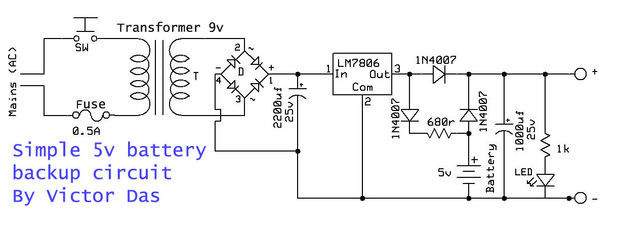
The signal that there is voltage in the network will be taken from the output of the stabilizer. If it is not there - extinguish the indicators!
Housing
Corps chose small. I had to try to fit everything in it. Some racks for mounting the wrap had to bite. The power supply will have to use an external one. The buttons for setting the hours, minutes and reset of seconds are displayed on the case.

List of rakes collected
- Proper nutrition. At first, the FPGA was programmed, but after flashing and connecting the board with LEDs, problems started. The programmer has stopped "seeing" and defining the chip. The problem was solved by installing filtering capacitors along each power supply line of the microcircuit.
- Asynchronous logic. Asynchronous reset counters are a typical solution for clocks on discrete counters. The use of asynchronous logic on the FPGA is strongly discouraged due to the unpredictability of work. Reliable solutions for FPGA - is a synchronous logic.
- Absence of automatic reset immediately after the FPGA firmware. After programming, the microcircuit stops working for some time, and then it starts working again. However, at the same time, apparently, the current values of the triggers are not reset. In this case, the clock begins to display on the screen some nonsense. In some cases, it may seem that everything is normal. This can be misleading and make you think that something is not so programmed. No, just need to turn off and turn on the power of the chip, so that all registers are reset. There is no reset input on the FPGA JTAG inputs, so an automatic reset after programming does not occur.
- No preset of register values. When programming Lattice microcircuits, it is necessary to take into account that Initial constructions for registers will not be synthesized. , , initial . . , N, . , , ( ) — .
- . , , , , . — . . . , . , .. 400 . — 315. , - . pull-up, ? , . . pull-down . "" . . … TT flux !!!
- Accuracy of hours. The generator on an hour quartz + TTL microcircuit stably runs away for a day for 3 minutes. A more accurate generator was able to make a CMOS chip. In general, the question of designing quartz oscillators is very extensive, and is beyond the scope of the article. See [6, 7, 8]
findings
As a result of the work done, I came to the following positive conclusions:
- Lattice FPGAs and their development environment are quite suitable for work;
- the use of universal HDL-languages, such as Verilog, allows you to change the FPGA manufacturer without any problems;
- Most of the problems that I encountered while developing the project were not related to the fact that the basis of the project is the FPGA (except for the moments with reset after firmware and register initialization);
- , 64...500 , , , , ;
- : 64 . 32 . , . 64 . RTC — DS1302, DS1307, DS3231, . , , GPS LCD , ~240 [9].
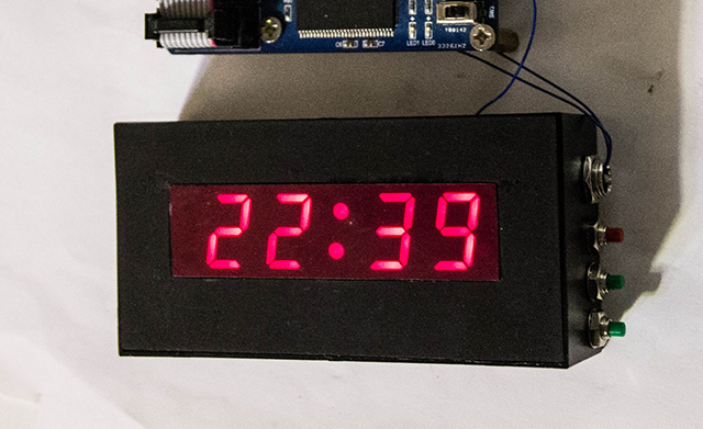
I had a great time studying the new FPGA, learned a lot of new things, attached a donated microcircuit, an LED screen and assembled a watch for the dacha. I wish you interesting projects and great mood!
The source code of the project on GitHub:
https://github.com/UA3MQJ/fpga_simple_clock
Links
- FPGA clock with Quartus II and some Verilog
- FPGA Clock
- Lattice products
- we.easyelectronics.ru - TT Flux-gel (Caution, shit!)
- MRB 1178. Electronic clock on MOS integrated circuits. Right allowance. - M .: Radio and communication, 1993. - 48 p.: Il .- (Mass radio library; Issue. 1178).
- Features of quartz oscillator frequency stabilization
- Quartz generators
- QUARTZ RESONATORS
- Watch GPS + LCD display WH0802
- “Stupid” watches on FPGA
Source: https://habr.com/ru/post/275863/
All Articles