VPLS. Label Distribution with BGP
Any engineer who has experienced MPLS knows that tags can be distributed in two ways: DU (Downstream Unsolicited) and DD (Downstream On-Demand). In the first case, the router begins to generate tags and send all its LDP neighbors to the prefixes to which it is next-hop. In the second case, the LSR will generate a pre-prefix label and transmit it only at the request of the upstream router. An example of the first case is the LDP protocol, the second case is RSVP-TE. And how are tags distributed in VPLS? Let's see.
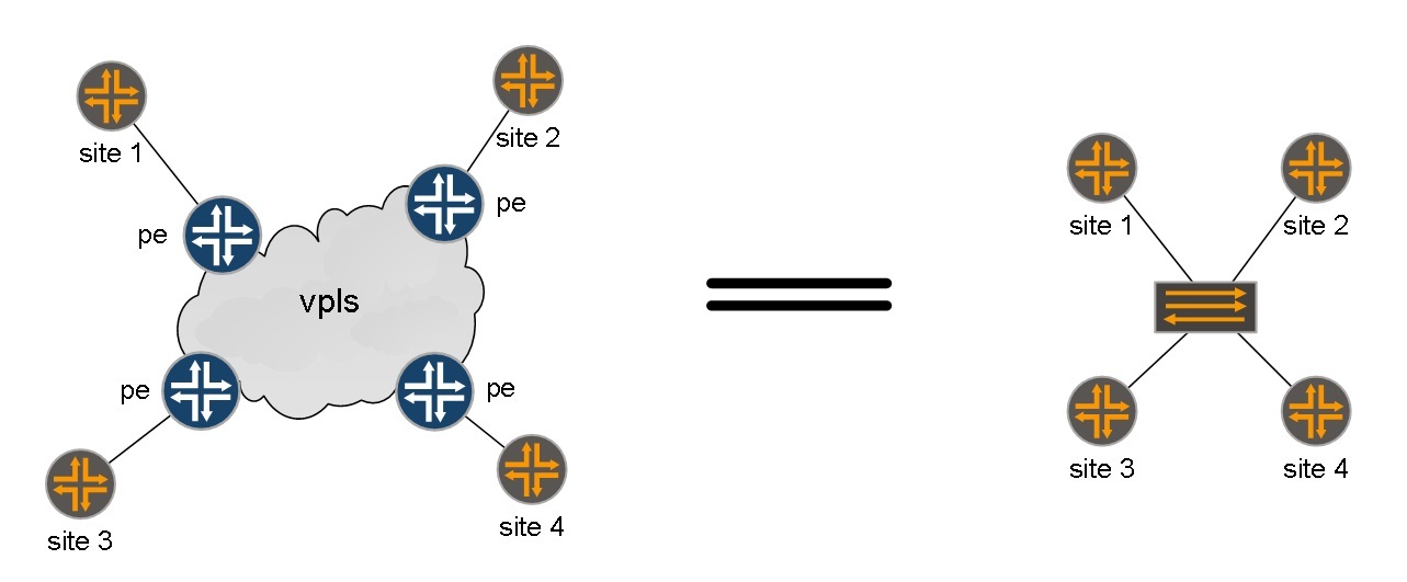
First, what is VPLS and why is it needed? Virtual Private LAN Services is LAN emulation for geographically (and not only) distributed networks. Virtual L2 connections are created between separated client sites (or data center elements), as a result of which the client sees the provider's network as a connection to the switch (to which its other sites are also connected):
Picture taken from the site inetzero.
There are two implementations of VPLS. One implementation provides BGP signaling (Draft Compell), the second establishes target LDP sessions between PE routers (Draft Martini).
')
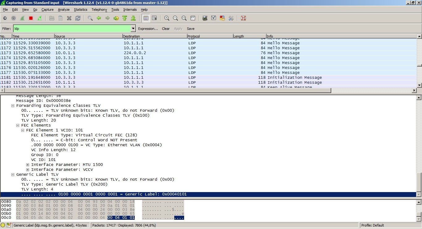
In the second case, everything is simple. The tags are distributed according to the Downstream Unsolicited principle using Label mapping of LDP messages with the FEC 128 type (the highlighted line is the generated tag):
It’s harder to understand how VPLS tags are distributed using BGP as an alarm (Compell Draft). This VPLS implementation uses control plane for the following tasks:
1. Automatic search for PE routers to which client sites are connected.
2. Distribution of MPLS tags for the implementation of a fully connected L2 topology between client sites.
First you need to create on each PE router to which client's sites are connected, routing instance with VPLS type:
Configure BGP alarm. For this type of VPLS, we need to enable address family l2vpn signaling:
We configure interfaces in the direction of the client (for example, as follows):
and do not forget to increase the MTU value on the interfaces towards the core of the network, the so-called core-face interfaces.
Now you can see if our connection is established:
As you can see the connection is established. On the output below you can see that between the client’s routers the OSPF neighborhood has risen and routes to loopbacks have appeared:
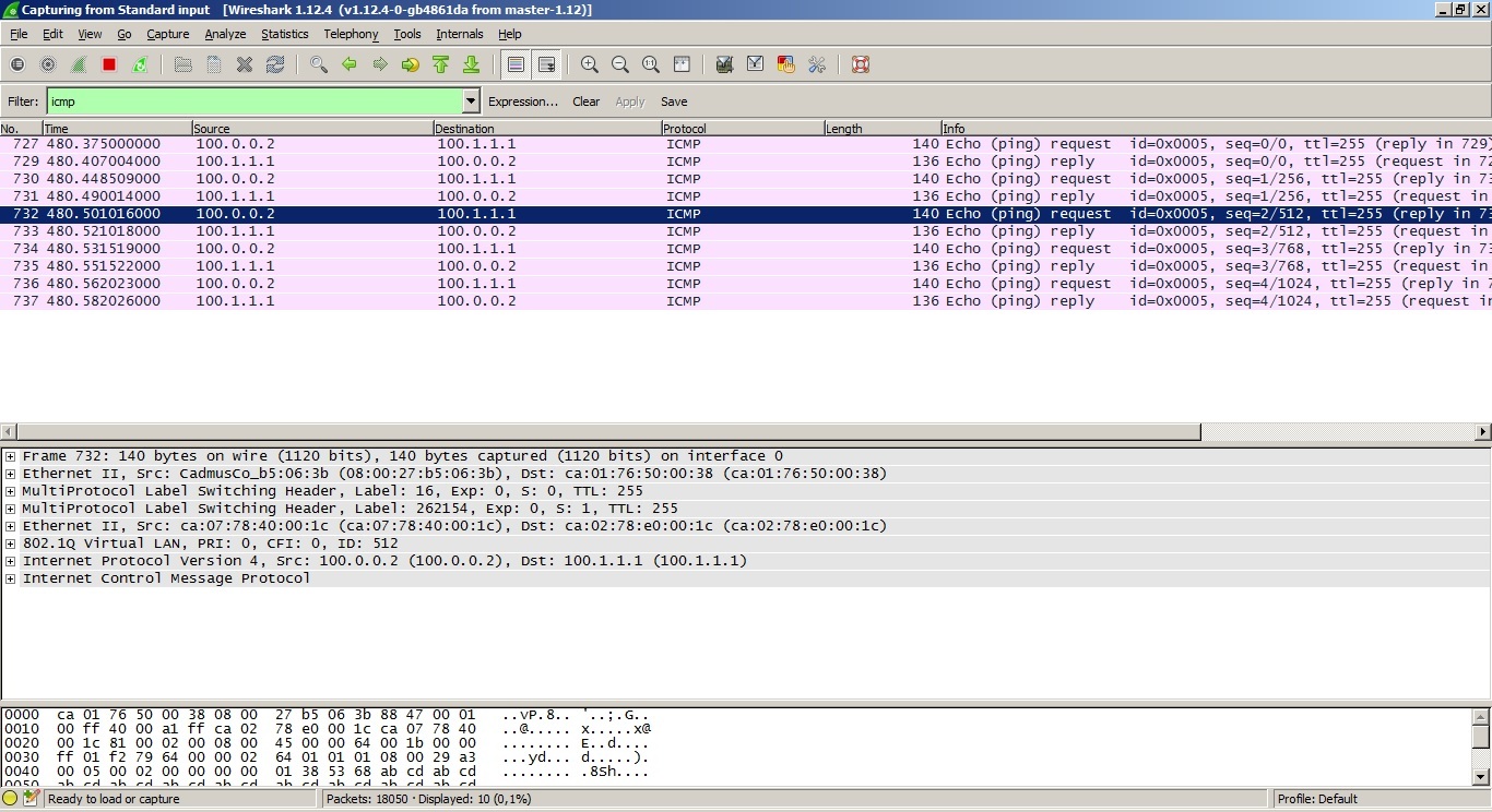
Packets transmitted over the network will look like this (which MTU you need to install, you can calculate it yourself):
Everything is working. Now let's see which tags are distributed between sites:
We are interested in this output line:
Incoming label: 262154, Outgoing label: 262145
That is, PE1 will use label 262145 to send a packet from CE1 to CE2, and with label 262154, PE1 will accept packets going from CE2 to CE1. But how are these tags generated and transmitted? We will understand in more detail. To do this, we’ll see a dump of BGP session traffic between PE1 and PE2 (now a BGP session is established between peers, but in real life 99% of the cases use route reflectors):
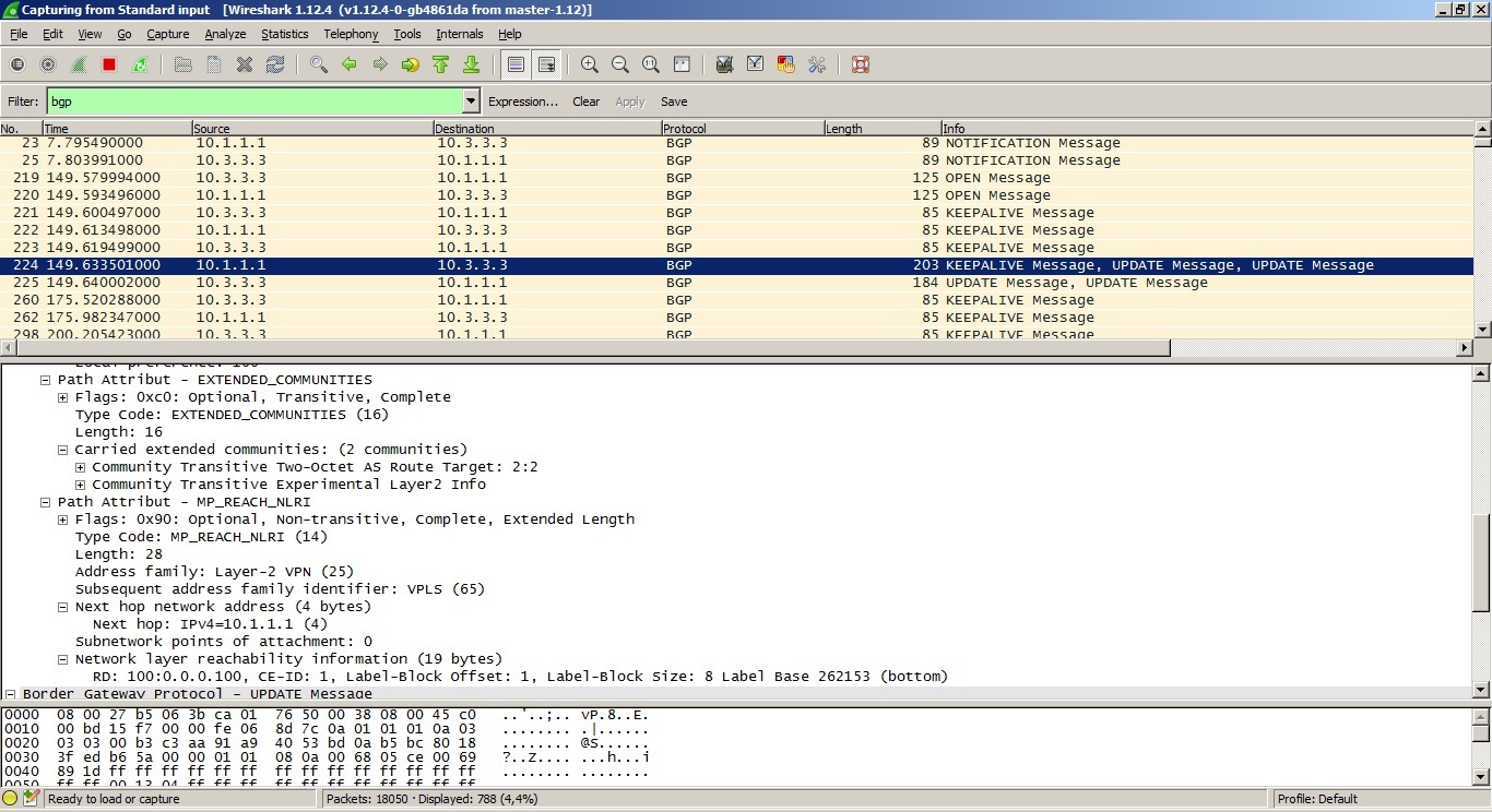
The first signaling problem is solved with the help of the notorious Route Target and Route Distinguisher. In the extended community line of the above dump, the RT value is visible, as with L3VPN, it is used to filter the routing information. Automatic lookup requires this type of routing-instance to have a configured RD value (by the way, it can be the same within a single VPLS domain).
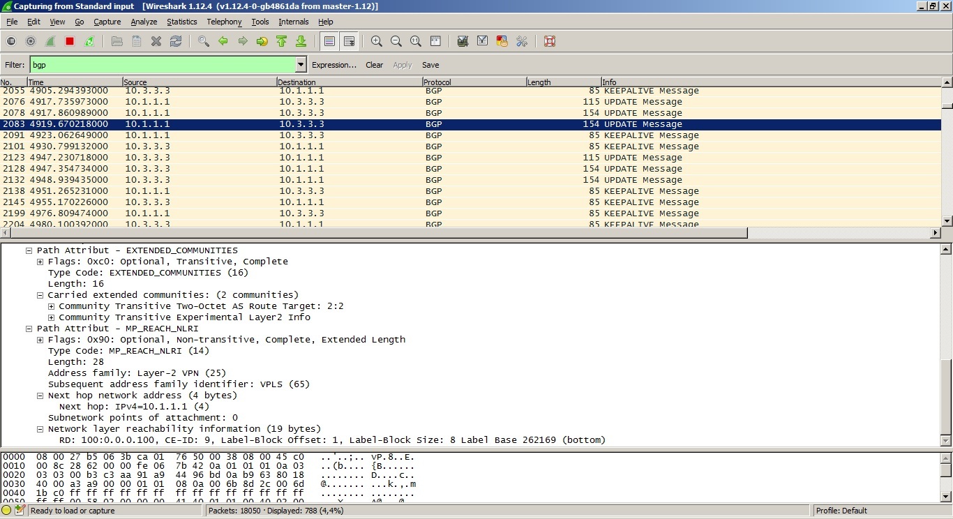
We now need to understand how the label distribution mechanism is implemented. Of interest to us is the string NLRI. The line contains several values, but unlike L3VPN or VPLS LDP Signaling, there is no exact indication of the generated label. Let us analyze each value of this field.
The first two fields I think everyone understands:
RD 100: 0.0.0.100 - this is RD (I think everyone knows what RD is, and no need to explain)
CE-ID - here is the Site-id configured by network administrators.
But the following three parameters are not familiar to us. The fact is that VPLS (draft Compella) distributes tags not one by one, but in blocks of 8 (by default) tags in a block. These fields characterize the distributed block of labels.
Label-Block Offcet is a label offset from the label base;
Label-Block Size - the size of the label block, in JunOS by default it is equal to 8 labels;
Label Base is a tag block database.
Now the math begins. The PE router to which the client's site is connected sends a message to all the other BGP Update PE routers, containing:
1. RD
2. CE-ID
3. Label-Block Offcet
4. Label-Block Size
5. Label Base
Since VPLS is a set of LSPs nested in other LSPs, we need to know:
1. With what tag to send a package to any site
2. From which site did the packet arrive with the specified label
The PE router, having received the above BGP Upgrade message, performs the following operations. using data from a neighbor:
Outgoing Label = Label Base Remote Site - Label-Block Offcet Remote Site + your Site ID
In our case, PE2 will perform the following operations: the value of the base 262153, subtracts the value of the label shift (we have 1) and adds its Site-ID to this value. This will be the outgoing tag to the site from which the BGP Update message came:
We obtain that, from the CE2 site to get to the CE1 site, PE2 must send a packet with the tag: 262153 (base) -1 (shift) +2 (site-id) = 262154. We are looking at the conclusion:
That's right, the outgoing label is 262154. Now, PE1, receiving a packet with the specified label 262154, knows that this packet was sent from PE2 of the CE2 site.
The incoming label is calculated in the same way, only the base value and the shift are taken on their own (generated by us for other PE routers), and the site-id of the necessary PE router is used as the site identifier:
Incoming label = your Label Base - your Label-Block Offcet + Site ID of the remote site
Let's change the configuration and perform the calculation again. Now we have the maximum number of sites 10, and our sites have identifiers 9 (CE1) and 6 (CE2) (there is no sense to configure the remaining 8 sites to understand the principle, since the calculations will be the same, but they will be more). Try again to calculate the value of the labels. Let's look at traffic dumps:
From PE1 to PE2:
From PE2 to PE1:
We have such data.
From PE1:
RD 100: 0.0.0.100
CE-ID 9
Label-Block Offcet 1
Label-Block Size 8
Label Base 262169
From PE2:
RD 200: 0.0.0.200
CE-ID 6
Label-Block Offcet 1
Label-Block Size 8
Label Base 262153
Now let's calculate what incoming and outgoing tags should be at the sites.
PE1 (site 9):
Inbound label from site 6: 262169-1 + 6 = 174
Outgoing label to site 6: 262153-1 + 9 = 161
PE2 (site 6):
Inbound tag from site 9: 262153-1 + 9 = 161
Outgoing label to site 9: 262169-1 + 6 = 174
And check the calculations made:
On PE1:
On PE2:
As you can see, we calculated everything correctly.
If you still do not understand how this mechanism works, I ask youto have funny pictures under the spoiler
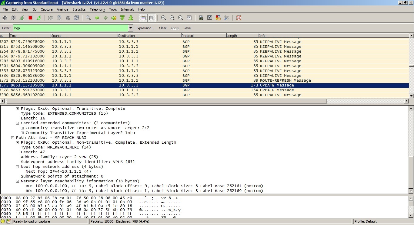
I want to add that if a client has for example 10 or 12 sites, then we need not one standard block of tags, but two. Therefore, in the BGP Update message there can be several values for the shift of the tags and the base:
And one more addition - JunOS by default uses a block of 8 tags, even if you need to connect only two or three sites. But using the set label-block-size command, you can change the number of labels in a block. JunOS supports 2, 4, 8, or 16 tags per block. But keep in mind that if you change this value on an already running VPLS domain, then all connections established in this VPLS domain will be broken and re-installed, with new parameters.
First, what is VPLS and why is it needed? Virtual Private LAN Services is LAN emulation for geographically (and not only) distributed networks. Virtual L2 connections are created between separated client sites (or data center elements), as a result of which the client sees the provider's network as a connection to the switch (to which its other sites are also connected):
Picture taken from the site inetzero.
There are two implementations of VPLS. One implementation provides BGP signaling (Draft Compell), the second establishes target LDP sessions between PE routers (Draft Martini).
')
In the second case, everything is simple. The tags are distributed according to the Downstream Unsolicited principle using Label mapping of LDP messages with the FEC 128 type (the highlighted line is the generated tag):
It’s harder to understand how VPLS tags are distributed using BGP as an alarm (Compell Draft). This VPLS implementation uses control plane for the following tasks:
1. Automatic search for PE routers to which client sites are connected.
2. Distribution of MPLS tags for the implementation of a fully connected L2 topology between client sites.
First you need to create on each PE router to which client's sites are connected, routing instance with VPLS type:
routing-instances { vpls-bgp-cutomer1 { instance-type vpls; interface ge-0/0/1.0; route-distinguisher 100:100; vrf-target { import target:1:1; export target:2:2; } protocols { vpls { site-range 5; no-tunnel-services; site ce1 { site-identifier 1; } } } } } Configure BGP alarm. For this type of VPLS, we need to enable address family l2vpn signaling:
root# show protocols bgp group internal { type internal; local-address 10.1.1.1; family l2vpn { signaling; } neighbor 10.3.3.3; } We configure interfaces in the direction of the client (for example, as follows):
root# show interfaces ge-0/0/1 vlan-tagging; encapsulation vlan-vpls; unit 0 { encapsulation vlan-vpls; vlan-id 512; family vpls; } and do not forget to increase the MTU value on the interfaces towards the core of the network, the so-called core-face interfaces.
Now you can see if our connection is established:
root# run show vpls connections Layer-2 VPN connections: Legend for connection status (St) EI -- encapsulation invalid NC -- interface encapsulation not CCC/TCC/VPLS EM -- encapsulation mismatch WE -- interface and instance encaps not same VC-Dn -- Virtual circuit down NP -- interface hardware not present CM -- control-word mismatch -> -- only outbound connection is up CN -- circuit not provisioned <- -- only inbound connection is up OR -- out of range Up -- operational OL -- no outgoing label Dn -- down LD -- local site signaled down CF -- call admission control failure RD -- remote site signaled down SC -- local and remote site ID collision LN -- local site not designated LM -- local site ID not minimum designated RN -- remote site not designated RM -- remote site ID not minimum designated XX -- unknown connection status IL -- no incoming label MM -- MTU mismatch MI -- Mesh-Group ID not available BK -- Backup connection ST -- Standby connection PF -- Profile parse failure PB -- Profile busy RS -- remote site standby SN -- Static Neighbor VM -- VLAN ID mismatch Legend for interface status Up -- operational Dn -- down Instance: vpls-bgp-cutomer1 Local site: ce1 (1) connection-site Type St Time last up # Up trans 2 rmt Up Jan 16 20:50:51 2016 1 Remote PE: 10.3.3.3, Negotiated control-word: No Incoming label: 262154, Outgoing label: 262145 Local interface: lsi.1048832, Status: Up, Encapsulation: VPLS Description: Intf - vpls vpls-bgp-cutomer1 local site 1 remote site 2 As you can see the connection is established. On the output below you can see that between the client’s routers the OSPF neighborhood has risen and routes to loopbacks have appeared:
R7(config)# *Jan 16 16:52:54.554: %OSPF-5-ADJCHG: Process 1, Nbr 20.1.1.1 on GigabitEthernet1/0.512 from LOADING to FULL, Loading Done R7(config)#sh R7(config)#do sh ip rou R7(config)#do sh ip route Codes: L - local, C - connected, S - static, R - RIP, M - mobile, B - BGP D - EIGRP, EX - EIGRP external, O - OSPF, IA - OSPF inter area N1 - OSPF NSSA external type 1, N2 - OSPF NSSA external type 2 E1 - OSPF external type 1, E2 - OSPF external type 2 i - IS-IS, su - IS-IS summary, L1 - IS-IS level-1, L2 - IS-IS level-2 ia - IS-IS inter area, * - candidate default, U - per-user static route o - ODR, P - periodic downloaded static route, H - NHRP, l - LISP + - replicated route, % - next hop override Gateway of last resort is not set 100.0.0.0/8 is variably subnetted, 4 subnets, 2 masks C 100.0.0.0/24 is directly connected, GigabitEthernet1/0.512 L 100.0.0.2/32 is directly connected, GigabitEthernet1/0.512 O 100.1.1.1/32 [110/2] via 100.0.0.1, 00:00:54, GigabitEthernet1/0.512 C 100.1.1.2/32 is directly connected, Loopback0 R7(config)#do ping 100.1.1.1 Type escape sequence to abort. Sending 5, 100-byte ICMP Echos to 100.1.1.1, timeout is 2 seconds: !!!!! Success rate is 100 percent (5/5), round-trip min/avg/max = 24/40/88 ms Packets transmitted over the network will look like this (which MTU you need to install, you can calculate it yourself):
Everything is working. Now let's see which tags are distributed between sites:
Instance: vpls-bgp-cutomer1 Local site: ce1 (1) connection-site Type St Time last up # Up trans 2 rmt Up Jan 16 20:50:51 2016 1 Remote PE: 10.3.3.3, Negotiated control-word: No Incoming label: 262154, Outgoing label: 262145 Local interface: lsi.1048832, Status: Up, Encapsulation: VPLS Description: Intf - vpls vpls-bgp-cutomer1 local site 1 remote site 2 Instance: vpls-bgp-customer1 Local site: ce2 (2) connection-site Type St Time last up # Up trans 1 rmt Up Jan 16 20:50:49 2016 1 Remote PE: 10.1.1.1, Negotiated control-word: No Incoming label: 262145, Outgoing label: 262154 Local interface: lsi.1048576, Status: Up, Encapsulation: VPLS Description: Intf - vpls vpls-bgp-customer1 local site 2 remote site 1 We are interested in this output line:
Incoming label: 262154, Outgoing label: 262145
That is, PE1 will use label 262145 to send a packet from CE1 to CE2, and with label 262154, PE1 will accept packets going from CE2 to CE1. But how are these tags generated and transmitted? We will understand in more detail. To do this, we’ll see a dump of BGP session traffic between PE1 and PE2 (now a BGP session is established between peers, but in real life 99% of the cases use route reflectors):
The first signaling problem is solved with the help of the notorious Route Target and Route Distinguisher. In the extended community line of the above dump, the RT value is visible, as with L3VPN, it is used to filter the routing information. Automatic lookup requires this type of routing-instance to have a configured RD value (by the way, it can be the same within a single VPLS domain).
We now need to understand how the label distribution mechanism is implemented. Of interest to us is the string NLRI. The line contains several values, but unlike L3VPN or VPLS LDP Signaling, there is no exact indication of the generated label. Let us analyze each value of this field.
The first two fields I think everyone understands:
RD 100: 0.0.0.100 - this is RD (I think everyone knows what RD is, and no need to explain)
CE-ID - here is the Site-id configured by network administrators.
But the following three parameters are not familiar to us. The fact is that VPLS (draft Compella) distributes tags not one by one, but in blocks of 8 (by default) tags in a block. These fields characterize the distributed block of labels.
Label-Block Offcet is a label offset from the label base;
Label-Block Size - the size of the label block, in JunOS by default it is equal to 8 labels;
Label Base is a tag block database.
Now the math begins. The PE router to which the client's site is connected sends a message to all the other BGP Update PE routers, containing:
1. RD
2. CE-ID
3. Label-Block Offcet
4. Label-Block Size
5. Label Base
Since VPLS is a set of LSPs nested in other LSPs, we need to know:
1. With what tag to send a package to any site
2. From which site did the packet arrive with the specified label
The PE router, having received the above BGP Upgrade message, performs the following operations. using data from a neighbor:
Outgoing Label = Label Base Remote Site - Label-Block Offcet Remote Site + your Site ID
In our case, PE2 will perform the following operations: the value of the base 262153, subtracts the value of the label shift (we have 1) and adds its Site-ID to this value. This will be the outgoing tag to the site from which the BGP Update message came:
We obtain that, from the CE2 site to get to the CE1 site, PE2 must send a packet with the tag: 262153 (base) -1 (shift) +2 (site-id) = 262154. We are looking at the conclusion:
Instance: vpls-bgp-customer1 Local site: ce2 (2) connection-site Type St Time last up # Up trans 1 rmt Up Jan 16 20:50:49 2016 1 Remote PE: 10.1.1.1, Negotiated control-word: No Incoming label: 262145, Outgoing label: 262154 Local interface: lsi.1048576, Status: Up, Encapsulation: VPLS Description: Intf - vpls vpls-bgp-customer1 local site 2 remote site 1 That's right, the outgoing label is 262154. Now, PE1, receiving a packet with the specified label 262154, knows that this packet was sent from PE2 of the CE2 site.
The incoming label is calculated in the same way, only the base value and the shift are taken on their own (generated by us for other PE routers), and the site-id of the necessary PE router is used as the site identifier:
Incoming label = your Label Base - your Label-Block Offcet + Site ID of the remote site
Let's change the configuration and perform the calculation again. Now we have the maximum number of sites 10, and our sites have identifiers 9 (CE1) and 6 (CE2) (there is no sense to configure the remaining 8 sites to understand the principle, since the calculations will be the same, but they will be more). Try again to calculate the value of the labels. Let's look at traffic dumps:
From PE1 to PE2:
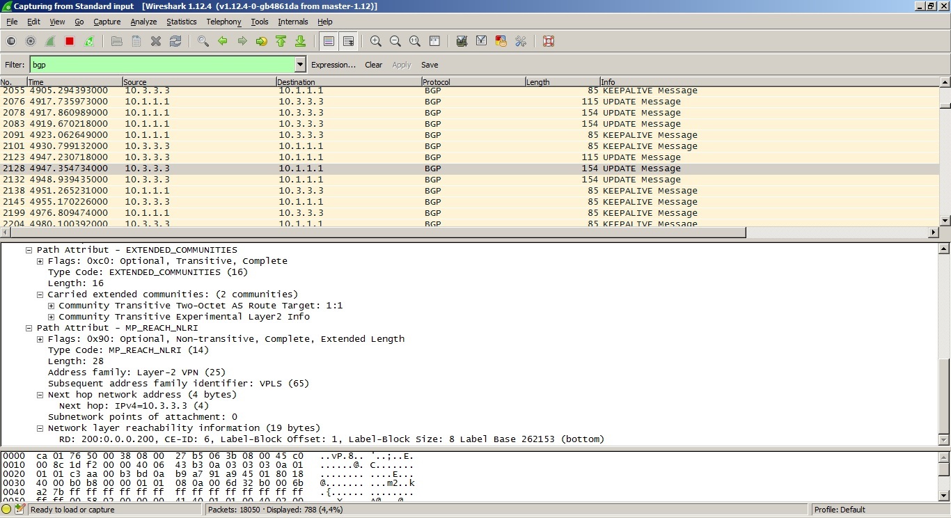
From PE2 to PE1:
We have such data.
From PE1:
RD 100: 0.0.0.100
CE-ID 9
Label-Block Offcet 1
Label-Block Size 8
Label Base 262169
From PE2:
RD 200: 0.0.0.200
CE-ID 6
Label-Block Offcet 1
Label-Block Size 8
Label Base 262153
Now let's calculate what incoming and outgoing tags should be at the sites.
PE1 (site 9):
Inbound label from site 6: 262169-1 + 6 = 174
Outgoing label to site 6: 262153-1 + 9 = 161
PE2 (site 6):
Inbound tag from site 9: 262153-1 + 9 = 161
Outgoing label to site 9: 262169-1 + 6 = 174
And check the calculations made:
On PE1:
Instance: vpls-bgp-cutomer1 Local site: ce1 (9) connection-site Type St Time last up # Up trans 6 rmt Up Jan 16 21:10:58 2016 1 Remote PE: 10.3.3.3, Negotiated control-word: No Incoming label: 262174, Outgoing label: 262161 Local interface: lsi.1048833, Status: Up, Encapsulation: VPLS Description: Intf - vpls vpls-bgp-cutomer1 local site 9 remote site 6 On PE2:
Instance: vpls-bgp-customer1 Local site: ce2 (6) connection-site Type St Time last up # Up trans 9 rmt Up Jan 16 21:10:53 2016 1 Remote PE: 10.1.1.1, Negotiated control-word: No Incoming label: 262161, Outgoing label: 262174 Local interface: lsi.1048577, Status: Up, Encapsulation: VPLS Description: Intf - vpls vpls-bgp-customer1 local site 6 remote site 9 As you can see, we calculated everything correctly.
If you still do not understand how this mechanism works, I ask you
in pictures
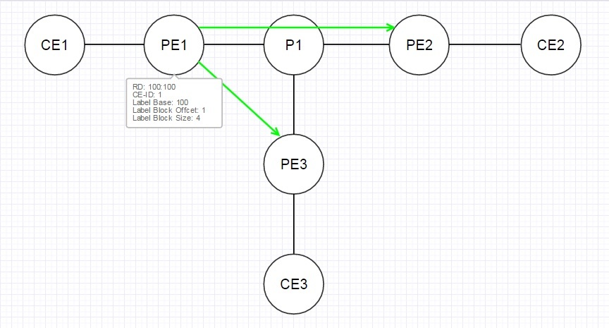
Consider this topology:

VPLS will create a fully connected topology between all three client sites:
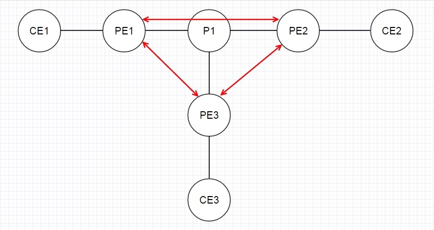
PE1 sends to PE2 and PE3 BGP Update messages with the data indicated in the illustration:
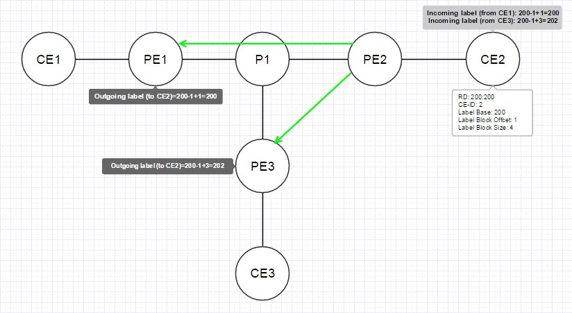
PE2 and PE3 calculate the values of outgoing tags to PE1 using the formula, and PE1 calculates incoming tags from PE2 and PE3:

The following images illustrate the process described above on PE2:
And on PE3:
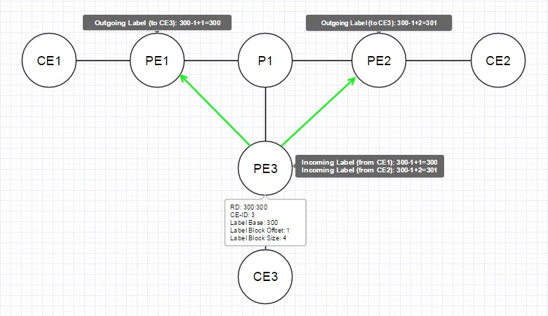
As a result, all PE routers have both incoming and outgoing tags for all sites:

VPLS will create a fully connected topology between all three client sites:
PE1 sends to PE2 and PE3 BGP Update messages with the data indicated in the illustration:
PE2 and PE3 calculate the values of outgoing tags to PE1 using the formula, and PE1 calculates incoming tags from PE2 and PE3:
The following images illustrate the process described above on PE2:
And on PE3:
As a result, all PE routers have both incoming and outgoing tags for all sites:
I want to add that if a client has for example 10 or 12 sites, then we need not one standard block of tags, but two. Therefore, in the BGP Update message there can be several values for the shift of the tags and the base:
And one more addition - JunOS by default uses a block of 8 tags, even if you need to connect only two or three sites. But using the set label-block-size command, you can change the number of labels in a block. JunOS supports 2, 4, 8, or 16 tags per block. But keep in mind that if you change this value on an already running VPLS domain, then all connections established in this VPLS domain will be broken and re-installed, with new parameters.
Source: https://habr.com/ru/post/275787/
All Articles