1-Wire slave on MK. Part 1: Iron

For one of the automation projects, it was necessary to make a device that is a slave 1-Wire device, accepts commands from the master and exposes the value of an analog signal at its outputs in the range from 0 to 10V.
After analyzing the line of standard microcircuits 1-Wire from Maxim, it became clear that there is no chip that will allow to implement such functionality.
Therefore, it was decided to implement a 1-Wire slave on the microcontroller. I hope this material will be interesting and useful to people who make "smart home" with their own hands, because 1-Wire is quite a popular bus in similar projects. As a stone, MK Cortex M0 + ATSAMD20G16 from Atmel was chosen, but the implementation in the code will be described in the second part. Looking ahead a bit, I’ll say that in the third part of the cycle we’ll talk about the implementation of our own family of devices for the One Wire File System (Linux) OWFS library. And today we will talk about some hardware solutions to which we arrived in the development process.
The discussion will mainly focus on how to connect the leg of the microcontroller to a 1-Wire bus with minimal damage to health. We will move from simple to complex.
Nothing to do
The first problem you encounter when trying to assemble a 1-Wire device on a microcontroller with a Cortex core is the power level of a 3.3V microcontroller, while on a 1-Wire bus we have 5V. You can use the tolerance of the legs of the microcontroller to 5V and connect as is, directly to the bus. Unfortunately, the legs of the SAM D20 are not tolerant to 5 volts, so this option is not suitable for us, but it's worth it to be noted. Although, putting the external tire directly onto the leg of the 3.3V stone is not the best idea. Firstly, there is the likelihood of unstable operation of other devices on the bus with parasitic power, secondly, on a long wire, you can “catch” a tip.
Level conversion
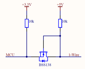
The simplest option is a bi-directional level converter on a transistor. It will require somewhere to take 5V from the side of the 1-Wire bus.
The first option is to make 5V on your device (in addition to 3.3V) to power the bus. As a consequence, the complexity of circuitry.
The second option is to lay the 1-Wire bus in three wires . The third wire is the + 5V power line. Of the problems - extra wire, voltage drop on a long wire.
')
Matching levels
If you really do not want to use + 5V, you can divide the signal line into 2 components (input and output)
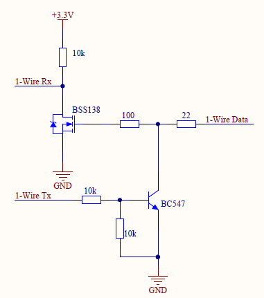
It is important to note that with such a scheme, the lines from the controller are inverse.
As a bonus, dividing the data line into 2 parts makes it possible to somewhat simplify further debugging of the software, since Allows you to see with the oscilloscope signals coming from us separately ( 1-Wire Tx line ), not mixed with signals from other devices on the bus.
Increase sustainability
In order to make the reception of data on 1-Wire more confident, it is necessary to make steep edges of pulses from the side of the microcontroller. To do this, we use a comparator from TI LMV331 , which will provide a more accurate and sharp transition between logical "0" and "1", as well as a hysteresis of 160mV. We will also replace the output bi-polar BC547 transistor on the field IRLML6346 and supply the TVS protective diode ESD5Z6 to 6V.
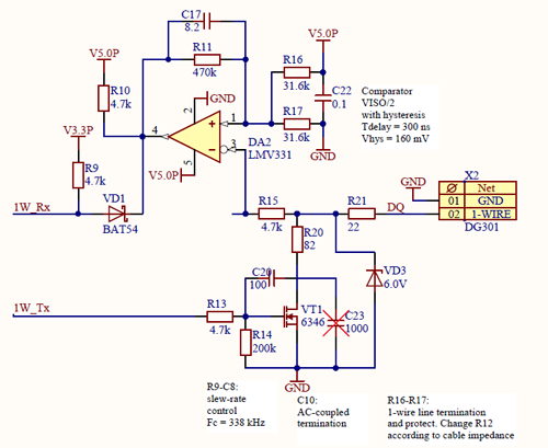
For this scheme, the comparator will need to be powered from 5V. Where they can be found above.
Untied 1-Wire
To ensure electrical isolation of the 1-Wire bus and the internal electronics of the device, we use an isolated level translator ADuM1201 and an isolated DC / DC converter TES 1-1211 . As in the previous case, divide the 1-Wire data line into 2 lines: 1W_Rx and 1W_Tx.
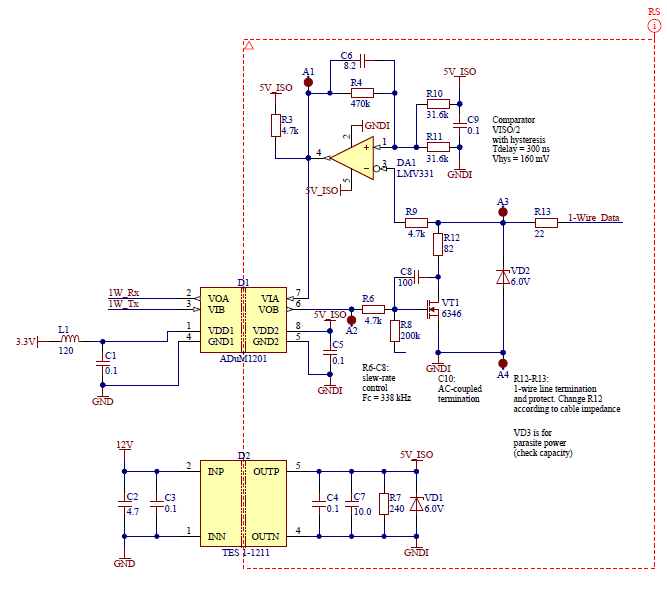
DC / DC converter from 12 to 5 volts taken for example, you can use the same 3.3 / 5.
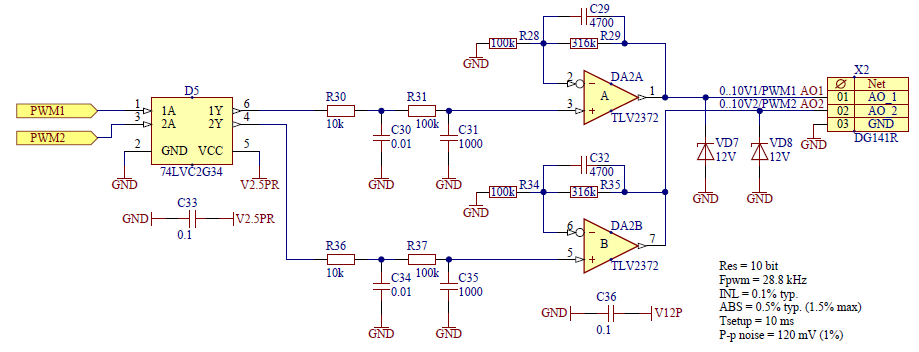
The rest of the circuitry
For completeness, we show the microcontroller connection circuitry, as well as 0-10V analogue output channels.
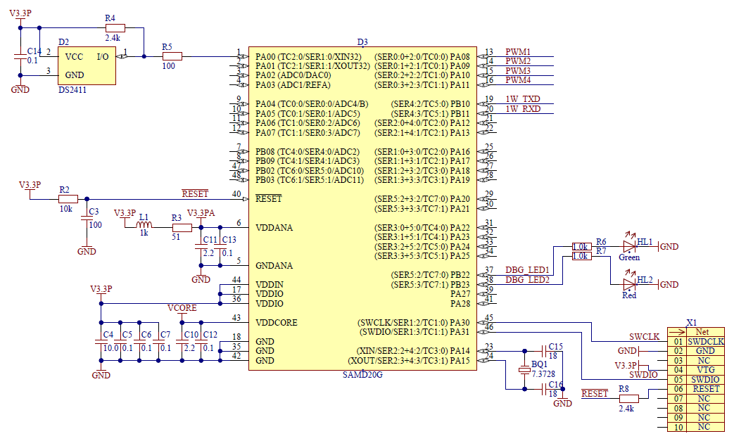
Since The 1-Wire protocol requires a unique address for each device on the bus; we put on the board a 1-Wire UID from Maxim DS2411 . Being a bus master for it, we will read its UID and use it as our own address. In DS2411, the family code is 0x01 (family code is the UID's most significant byte). On the OWFS website, we will select an unused family code for our new device and replace the first byte.
As already mentioned, in the second part we will start the software implementation of the 1-Wire Slave protocol.
Source: https://habr.com/ru/post/275373/
All Articles