Office lighting control over Wi-Fi. Part 2: Q-touch sensor technology
We continue our ambitious “Hello, World!” On the Atmel SAMD21 Xplained debug card, launched in the first part , which described the operation with the WINC1500 Wi-Fi module.
Today we will demonstrate an example of processing touch buttons and a slider using the Q-touch library.
In the third part of the cycle, as promised, the data from these sensors will be “packed” into the ModBus TCP package and transmitted via Wi-Fi to the lighting control system in our office.
To begin with, let's see what kind of Q-touch. This is the atmelovsky implementation of the processing technology of resistive touch buttons and sliders, followed by a library to simplify working with them. And in all SAMD microcontrollers, a hardware Q-touch controller (so-called peripheral touch controller (PTC)) is implemented. It allows both to minimize the number of used microcontroller pins and the load on the computational core.
As sensors, we will use the ATQT1-XPRO expansion module, which, as mentioned in the last article, can be installed on any debugging board from the Xplained Pro series.
Qtouch technology supports the following types of sensors: buttons, sliders, rotors, and proximity detection.

QTouch is based on measuring its own capacity, and QMatrix on measuring joint.
Measurement using our own capacitance implies charging a sensitive electrode of unknown capacitance to a known potential. The resulting charge is transferred to the measuring circuit. Using charge-and-transfer cycles, you can measure the capacitance of a sensitive plate.
Measurement using a joint capacitance is carried out using two electrodes. One of the electrodes acts as an emitter, which takes charge, which is transmitted by logical pulses in a sequential (burst) mode. The second electrode acts as a receiver, which communicates with the emitter through the dielectric from which the touch panel is made. When a finger touches the panel, the joint field is reduced, and the touch is detected.
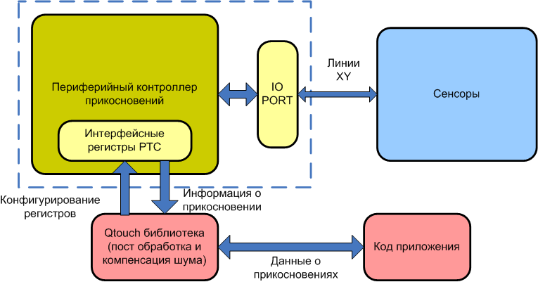
In the SAMD20 and 21 series of controllers, QTouch / QMatrix technology is embedded. The special unit that is responsible for it is the peripheral touch controller (PTC). The scheme of the entire system is shown in the figure below.
For the development of new periphery it is very convenient to use example projects. And for QTouch there is also a special plugin QTouch Composer, which makes the development of visual. But if you need to embed the touch buttons in an existing project, you need to understand the entire sequence of actions and settings. Now this is what we do.
The general scheme of the library is shown in the block diagram:

We add to the project using a PTC and RTC wizard.
')
The configuration is configured in the file touch_config_samd.h. Let's walk through the main parameters.
First you need to choose the method of determining the touch: own capacity or joint. The selection is made by setting the values of the corresponding constants.
The priority of interrupts from the PTC controller at the end of the conversion can be from 0 to 3 (0 is the highest priority). And installed using defajna:
As mentioned above, to determine the touch using a joint capacitance, you need two lines: X and Y. The samd21 has 16 lines X and Y. In this case (using debugging with an expansion card) we have no choice on which pair of lines which button / slider / rotor wind up. The order of specifying output pairs sets the channel numbers. For a rotor / slider, it is imperative to use the same Y line for all channels. The indication of lines is carried out using an appropriate define:
Specify the number of channels (for the button is always 1 channel, for the rotor / slider from 3 to 8). In our case, 2 buttons and 4 channels per rotor and slider are used, a total of 10 channels:
Specify the number of sensors (we have 2 buttons, one slider and one rotor total 4):
Specify the number of rotors / sensors (we have one slider and one rotor total 2):
We proceed to the indication of the transformation parameters.
The level of filtering affects the accuracy and speed of the conversion. The higher the level (from 1 to 64), the more samples there are in 1 conversion, which improves the noise / signal ratio, but increases the conversion time.
Amplification of the signal from the sensors is configured per channel. Values range from 1 to 32.
Set the polling period in milliseconds.
As for the mechanical buttons, for the touch has a kind of anti-bounce. It lies in the fact that you specify during the course of measurement cycles the signal level must exceed the threshold level for detecting the touch of a button / rotor / slider.
It happens that some object touches the sensor for a long time. In this case, it is necessary after some time to recalibrate the sensor taking into account the new working conditions. To set the time after which the recalibration takes place, a special constant is used. The time is set in units of 200 ms (i.e. a value of 5 corresponds to 1 second). If the time is set to 0, then automatic recalibration will not be carried out.
You can enable or disable debug output for Qtouch Analyzer:
For some strange reasons, Atmel did not include the standard PTC initialization functions (as with other peripherals) and the definition of several necessary constants. Therefore, all this must be done independently. What we now do.
First of all, we need to initialize the RTC, because the interrupts from it will check the button triggering in our case. We configure RTC, register callback, write code for callback. RTC will generate interrupts every 1 ms, if as many ms have passed as we have an interval between reading the buttons, then set the appropriate flag, which will be checked in the main.
Required Ads:
Now you need to configure PTC itself. First we add the necessary structures:
Macros:
Defaults:
Variables:
PTC clocking configuration function:
Sensor configuration:
In main, you need to initialize the RTC timer, initialize PTC, configure sleep mode (if necessary), and enable global interrupts:
Suppose, in the simplest case, we have LEDs touching the button and the position of the slider. The rotor will not touch.
In while (1) it is necessary to add the function of falling asleep (if necessary), the function of handling touch and ignition of the corresponding LEDs to indicate the touch:
Compile, fill, enjoy.
Today we will demonstrate an example of processing touch buttons and a slider using the Q-touch library.
In the third part of the cycle, as promised, the data from these sensors will be “packed” into the ModBus TCP package and transmitted via Wi-Fi to the lighting control system in our office.
To begin with, let's see what kind of Q-touch. This is the atmelovsky implementation of the processing technology of resistive touch buttons and sliders, followed by a library to simplify working with them. And in all SAMD microcontrollers, a hardware Q-touch controller (so-called peripheral touch controller (PTC)) is implemented. It allows both to minimize the number of used microcontroller pins and the load on the computational core.
As sensors, we will use the ATQT1-XPRO expansion module, which, as mentioned in the last article, can be installed on any debugging board from the Xplained Pro series.
Qtouch technology supports the following types of sensors: buttons, sliders, rotors, and proximity detection.
Qtouch and QMatrix Technologies
QTouch is based on measuring its own capacity, and QMatrix on measuring joint.
Measurement using our own capacitance implies charging a sensitive electrode of unknown capacitance to a known potential. The resulting charge is transferred to the measuring circuit. Using charge-and-transfer cycles, you can measure the capacitance of a sensitive plate.
Measurement using a joint capacitance is carried out using two electrodes. One of the electrodes acts as an emitter, which takes charge, which is transmitted by logical pulses in a sequential (burst) mode. The second electrode acts as a receiver, which communicates with the emitter through the dielectric from which the touch panel is made. When a finger touches the panel, the joint field is reduced, and the touch is detected.
| Qtouch | Qmatrix |
|---|---|
| Own capacity | Joint capacity |
| Reliable and simple electrode design | Well defined pressure detection area |
| Ideal for a small number of sensors. | Ideal for a large number of sensors (more than 10) |
| Good definition of approximation, at a greater distance | Well adaptable to humidity and environment |
| Any form of electrode is theoretically possible. | Passive tracking - longer paths are possible. |
| Easy to adjust sensitivity | Well adaptable to noise and noise on the ground |
In the SAMD20 and 21 series of controllers, QTouch / QMatrix technology is embedded. The special unit that is responsible for it is the peripheral touch controller (PTC). The scheme of the entire system is shown in the figure below.
Create a project
For the development of new periphery it is very convenient to use example projects. And for QTouch there is also a special plugin QTouch Composer, which makes the development of visual. But if you need to embed the touch buttons in an existing project, you need to understand the entire sequence of actions and settings. Now this is what we do.
The general scheme of the library is shown in the block diagram:
We add to the project using a PTC and RTC wizard.
')
The configuration is configured in the file touch_config_samd.h. Let's walk through the main parameters.
First you need to choose the method of determining the touch: own capacity or joint. The selection is made by setting the values of the corresponding constants.
#define DEF_TOUCH_MUTLCAP (1u) #define DEF_TOUCH_SELFCAP (0u) The priority of interrupts from the PTC controller at the end of the conversion can be from 0 to 3 (0 is the highest priority). And installed using defajna:
#define DEF_TOUCH_PTC_ISR_LVL (1u) As mentioned above, to determine the touch using a joint capacitance, you need two lines: X and Y. The samd21 has 16 lines X and Y. In this case (using debugging with an expansion card) we have no choice on which pair of lines which button / slider / rotor wind up. The order of specifying output pairs sets the channel numbers. For a rotor / slider, it is imperative to use the same Y line for all channels. The indication of lines is carried out using an appropriate define:
#define DEF_MUTLCAP_NODES X(8), Y(10), X(9), Y(10), X(2), Y(12), X(3), Y(12), \ X(8), Y(12), X(9), Y(12), X(2), Y(13), X(3), Y(13), \ X(8), Y(13), X(9), Y(13) Specify the number of channels (for the button is always 1 channel, for the rotor / slider from 3 to 8). In our case, 2 buttons and 4 channels per rotor and slider are used, a total of 10 channels:
#define DEF_MUTLCAP_NUM_CHANNELS (10) /* Total number of channels */ Specify the number of sensors (we have 2 buttons, one slider and one rotor total 4):
#define DEF_MUTLCAP_NUM_SENSORS (4) /* Total number of sensors */ Specify the number of rotors / sensors (we have one slider and one rotor total 2):
#define DEF_MUTLCAP_NUM_ROTORS_SLIDERS (2) /* Number of rotor sliders */ We proceed to the indication of the transformation parameters.
The level of filtering affects the accuracy and speed of the conversion. The higher the level (from 1 to 64), the more samples there are in 1 conversion, which improves the noise / signal ratio, but increases the conversion time.
#define DEF_MUTLCAP_FILTER_LEVEL FILTER_LEVEL_32 /* Filter level */ Amplification of the signal from the sensors is configured per channel. Values range from 1 to 32.
#define DEF_MUTLCAP_GAIN_PER_NODE GAIN_1, GAIN_1, GAIN_1, GAIN_1, GAIN_1, \ GAIN_1, GAIN_1, GAIN_1, GAIN_1, GAIN_1 Set the polling period in milliseconds.
#define DEF_TOUCH_MEASUREMENT_PERIOD_MS 20u As for the mechanical buttons, for the touch has a kind of anti-bounce. It lies in the fact that you specify during the course of measurement cycles the signal level must exceed the threshold level for detecting the touch of a button / rotor / slider.
#define DEF_MUTLCAP_DI 4u It happens that some object touches the sensor for a long time. In this case, it is necessary after some time to recalibrate the sensor taking into account the new working conditions. To set the time after which the recalibration takes place, a special constant is used. The time is set in units of 200 ms (i.e. a value of 5 corresponds to 1 second). If the time is set to 0, then automatic recalibration will not be carried out.
#define DEF_MUTLCAP_MAX_ON_DURATION 0u You can enable or disable debug output for Qtouch Analyzer:
<cut />#define DEF_TOUCH_QDEBUG_ENABLE 0u For some strange reasons, Atmel did not include the standard PTC initialization functions (as with other peripherals) and the definition of several necessary constants. Therefore, all this must be done independently. What we now do.
First of all, we need to initialize the RTC, because the interrupts from it will check the button triggering in our case. We configure RTC, register callback, write code for callback. RTC will generate interrupts every 1 ms, if as many ms have passed as we have an interval between reading the buttons, then set the appropriate flag, which will be checked in the main.
Required Ads:
Timer Functions
// RTC Interrupt timing definition #define TIME_PERIOD_1MSEC 33u /* ! QTouch Library Timing info. */ touch_time_t touch_time; volatile uint16_t touch_time_counter = 0u; struct rtc_module rtc_instance; : void rtc_overflow_callback(void) { /* Do something on RTC overflow here */ if(touch_time_counter == touch_time.measurement_period_ms) { touch_time.time_to_measure_touch = 1u; touch_time.current_time_ms = touch_time.current_time_ms + touch_time.measurement_period_ms; touch_time_counter = 0u; } else { touch_time_counter++; } } void configure_rtc_callbacks(void) { /* register callback */ rtc_count_register_callback(&rtc_instance, rtc_overflow_callback, RTC_COUNT_CALLBACK_OVERFLOW); /* Enable callback */ rtc_count_enable_callback(&rtc_instance,RTC_COUNT_CALLBACK_OVERFLOW); } void configure_rtc_count(void) { struct rtc_count_config config_rtc_count; rtc_count_get_config_defaults(&config_rtc_count); config_rtc_count.prescaler = RTC_COUNT_PRESCALER_DIV_1; config_rtc_count.mode = RTC_COUNT_MODE_16BIT; config_rtc_count.continuously_update = true; /* initialize rtc */ rtc_count_init(&rtc_instance,RTC,&config_rtc_count); /* enable rtc */ rtc_count_enable(&rtc_instance); } void timer_init(void) { /* Configure and enable RTC */ configure_rtc_count(); /* Configure and enable callback */ configure_rtc_callbacks(); /* Set Timer Period */ rtc_count_set_period(&rtc_instance,TIME_PERIOD_1MSEC); } Now you need to configure PTC itself. First we add the necessary structures:
Structures for PTC
static touch_mutlcap_config_t mutlcap_config = { DEF_MUTLCAP_NUM_CHANNELS, /* Mutual Cap number of channels. */ DEF_MUTLCAP_NUM_SENSORS, /* Mutual Cap number of sensors. */ DEF_MUTLCAP_NUM_ROTORS_SLIDERS, /* Mutual Cap number of rotors and sliders. */ /* Mutual Cap GLOBAL SENSOR CONFIGURATION INFO. */ { DEF_MUTLCAP_DI, /* uint8_t di; Sensor detect integration (DI) limit. */ /* Interchanging Negative and Positive Drift rate, since Signal increases on Touch. */ DEF_MUTLCAP_ATCH_DRIFT_RATE, /* uint8_t neg_drift_rate; Sensor negative drift rate. */ DEF_MUTLCAP_TCH_DRIFT_RATE, /* uint8_t pos_drift_rate; Sensor positive drift rate. */ DEF_MUTLCAP_MAX_ON_DURATION, /* uint8_t max_on_duration; Sensor maximum on duration. */ DEF_MUTLCAP_DRIFT_HOLD_TIME, /* uint8_t drift_hold_time; Sensor drift hold time. */ DEF_MUTLCAP_ATCH_RECAL_DELAY, /* uint8_t pos_recal_delay; Sensor positive recalibration delay. */ DEF_MUTLCAP_CAL_SEQ1_COUNT, DEF_MUTLCAP_CAL_SEQ2_COUNT, DEF_MUTLCAP_ATCH_RECAL_THRESHOLD, /* recal_threshold_t recal_threshold; Sensor recalibration threshold. */ }, { mutlcap_gain_per_node, /* Mutual Cap channel gain setting. */ DEF_MUTLCAP_FREQ_MODE, /* Mutual Cap noise counter measure enable/disable. */ DEF_MUTLCAP_CLK_PRESCALE, DEF_MUTLCAP_SENSE_RESISTOR, DEF_MUTLCAP_CC_CAL_CLK_PRESCALE, DEF_MUTLCAP_CC_CAL_SENSE_RESISTOR, mutlcap_freq_hops, DEF_MUTLCAP_FILTER_LEVEL, /* Mutual Cap filter level setting. */ DEF_MUTLCAP_AUTO_OS, /* Mutual Cap auto oversamples setting.*/ }, mutlcap_data_blk, /* Mutual Cap data block index. */ PRIV_MUTLCAP_DATA_BLK_SIZE, /* Mutual Cap data block size. */ mutlcap_xy_nodes, /* Mutual Cap channel nodes. */ DEF_MUTLCAP_QUICK_REBURST_ENABLE, DEF_MUTLCAP_FILTER_CALLBACK /* Mutual Cap filter callback function pointer. */ }; touch_config_t touch_config = { &mutlcap_config, /* Pointer to Mutual Cap configuration structure. */ NULL, DEF_TOUCH_PTC_ISR_LVL, /* PTC interrupt level. */ }; Macros:
#define GET_MUTLCAP_SENSOR_STATE(SENSOR_NUMBER) p_mutlcap_measure_data-> \ p_sensor_states[(SENSOR_NUMBER / \ 8)] & (1 << (SENSOR_NUMBER % 8)) Defaults:
#define DEF_MUTLCAP_CAL_SEQ1_COUNT 8 #define DEF_MUTLCAP_CAL_SEQ2_COUNT 4 #define DEF_MUTLCAP_CC_CAL_CLK_PRESCALE PRSC_DIV_SEL_8 #define DEF_MUTLCAP_CC_CAL_SENSE_RESISTOR RSEL_VAL_100 #define DEF_MUTLCAP_QUICK_REBURST_ENABLE 1u #define PTC_APBC_BITMASK (1u << 19u) Variables:
static uint8_t mutlcap_data_blk[PRIV_MUTLCAP_DATA_BLK_SIZE]; uint16_t mutlcap_xy_nodes[DEF_MUTLCAP_NUM_CHANNELS * 2] = {DEF_MUTLCAP_NODES}; gain_t mutlcap_gain_per_node[DEF_MUTLCAP_NUM_CHANNELS]= {DEF_MUTLCAP_GAIN_PER_NODE}; freq_hop_sel_t mutlcap_freq_hops[3u] = {DEF_MUTLCAP_HOP_FREQS}; PTC clocking configuration function:
void touch_configure_ptc_clock(void) { struct system_gclk_chan_config gclk_chan_conf; system_gclk_chan_get_config_defaults(&gclk_chan_conf); gclk_chan_conf.source_generator = GCLK_GENERATOR_3; system_gclk_chan_set_config(PTC_GCLK_ID, &gclk_chan_conf); system_gclk_chan_enable(PTC_GCLK_ID); system_apb_clock_set_mask(SYSTEM_CLOCK_APB_APBC, PTC_APBC_BITMASK); } Sensor configuration:
touch_ret_t touch_sensors_config(void) { touch_ret_t touch_ret = TOUCH_SUCCESS; sensor_id_t sensor_id; touch_ret = touch_mutlcap_sensor_config(SENSOR_TYPE_KEY, CHANNEL_0, CHANNEL_0, NO_AKS_GROUP, 20u, HYST_6_25, RES_8_BIT,0, &sensor_id); if (touch_ret != TOUCH_SUCCESS) while (1); touch_ret = touch_mutlcap_sensor_config(SENSOR_TYPE_KEY, CHANNEL_1, CHANNEL_1, NO_AKS_GROUP, 20u, HYST_6_25, RES_8_BIT,0, &sensor_id); if (touch_ret != TOUCH_SUCCESS) while (1); touch_ret = touch_mutlcap_sensor_config(SENSOR_TYPE_ROTOR, CHANNEL_6, CHANNEL_9, NO_AKS_GROUP, 20u, HYST_6_25, RES_8_BIT,0, &sensor_id); if (touch_ret != TOUCH_SUCCESS) while (1); touch_ret = touch_mutlcap_sensor_config(SENSOR_TYPE_SLIDER, CHANNEL_2, CHANNEL_5, NO_AKS_GROUP, 20u, HYST_6_25, RES_8_BIT,0, &sensor_id); if (touch_ret != TOUCH_SUCCESS) while (1); return (touch_ret); } Initialization of sensors and common parameters
touch_ret_t touch_sensors_init(void) { touch_ret_t touch_ret = TOUCH_SUCCESS; /* Setup and enable generic clock source for PTC module. */ touch_configure_ptc_clock(); touch_time.measurement_period_ms = DEF_TOUCH_MEASUREMENT_PERIOD_MS; /* Initialize touch library for Mutual Cap operation. */ touch_ret = touch_mutlcap_sensors_init(&touch_config); if (touch_ret != TOUCH_SUCCESS) { while (1u); /* Check API Error return code. */ } #if DEF_TOUCH_QDEBUG_ENABLE == 1 QDebug_Init(); #endif /* configure the touch library sensors. */ touch_ret = touch_sensors_config(); if (touch_ret != TOUCH_SUCCESS) { while (1u); /* Check API Error return code. */ } /* Auto Tuning setting for calibration. * * AUTO_TUNE_PRSC: When Auto tuning of pre-scaler is selected * the PTC uses the user defined internal series resistor setting * (DEF_MUTLCAP_SENSE_RESISTOR) and the pre-scaler is adjusted * to slow down the PTC operation to ensure full charge transfer. * * AUTO_TUNE_RSEL: When Auto tuning of the series resistor is * selected the PTC runs at user defined pre-scaler setting speed * (DEF_MUTLCAP_CLK_PRESCALE) and the internal series resistor is * tuned automatically to the optimum value to allow for full * charge transfer. * * AUTO_TUNE_NONE: When manual tuning option is selected (AUTO_TUNE_NONE), * the user defined values of PTC pre-scaler and series resistor is used * for PTC operation as given in DEF_MUTLCAP_CLK_PRESCALE and * DEF_MUTLCAP_SENSE_RESISTOR * */ touch_ret = touch_mutlcap_sensors_calibrate(AUTO_TUNE_RSEL); if (touch_ret != TOUCH_SUCCESS) { while (1u); /* Check API Error return code. */ } return (touch_ret); } Measurement and interrupt handler at the end of measurement
void touch_mutlcap_measure_complete_callback( void ) { #if DEF_TOUCH_QDEBUG_ENABLE == 1 /* Send out the Touch debug information data each time when Touch * measurement process is completed . * The Touch Signal and Touch Delta values are always sent. * Touch Status change, Rotor-Slider Position change and Sensor * Reference * values can be optionally sent using the masks below. */ QDebug_SendData( TOUCH_CHANNEL_REF_CHANGE | TOUCH_ROTOR_SLIDER_POS_CHANGE | TOUCH_STATUS_CHANGE ); /* QT600 two-way QDebug communication application Example. */ /* Process any commands received from QTouch Studio. */ QDebug_ProcessCommands(); #endif if (!(p_mutlcap_measure_data->acq_status & TOUCH_BURST_AGAIN)) { /* Set the Mutual Cap measurement done flag. */ p_mutlcap_measure_data->measurement_done_touch = 1u; } } touch_ret_t touch_sensors_measure(void) { touch_ret_t touch_ret = TOUCH_SUCCESS; if (touch_time.time_to_measure_touch == 1u) { /* Start a touch sensors measurement process. */ touch_ret = touch_mutlcap_sensors_measure( touch_time.current_time_ms, NORMAL_ACQ_MODE, touch_mutlcap_measure_complete_callback); if ((touch_ret != TOUCH_ACQ_INCOMPLETE) && (touch_ret == TOUCH_SUCCESS)) { touch_time.time_to_measure_touch = 0u; } else if ((touch_ret != TOUCH_SUCCESS) &&(touch_ret != TOUCH_ACQ_INCOMPLETE)) { while (1); /* Reaching this point can be due to - * 1. The api has retured an error due to a invalid * input parameter. * 2. The api has been called during a invalid Touch * Library state. */ } } return (touch_ret); } In main, you need to initialize the RTC timer, initialize PTC, configure sleep mode (if necessary), and enable global interrupts:
Initialization in main
system_interrupt_enable_global ();
// Initialize timer. (RTC actually
timer_init ();
// Initialize QTouch library and configure touch sensors.
touch_sensors_init ();
NVMCTRL-> CTRLB.bit.SLEEPPRM = 3;
system_set_sleepmode (SYSTEM_SLEEPMODE_STANDBY);
// Initialize timer. (RTC actually
timer_init ();
// Initialize QTouch library and configure touch sensors.
touch_sensors_init ();
NVMCTRL-> CTRLB.bit.SLEEPPRM = 3;
system_set_sleepmode (SYSTEM_SLEEPMODE_STANDBY);
Suppose, in the simplest case, we have LEDs touching the button and the position of the slider. The rotor will not touch.
In while (1) it is necessary to add the function of falling asleep (if necessary), the function of handling touch and ignition of the corresponding LEDs to indicate the touch:
Code for while (1)
// Goto STANDBY sleep mode, unless woken by timer or PTC interrupt. system_sleep(); // Start touch sensor measurement, if touch_time.time_to_measure_touch flag is set by timer. touch_sensors_measure(); if ((p_mutlcap_measure_data->measurement_done_touch == 1u)) { p_mutlcap_measure_data->measurement_done_touch = 0u; // Get touch sensor states button1_state = GET_MUTLCAP_SENSOR_STATE(0); button2_state = GET_MUTLCAP_SENSOR_STATE(1); rotor_state = GET_MUTLCAP_SENSOR_STATE(2); slider_state = GET_MUTLCAP_SENSOR_STATE(3); if (button1_state) { if(button_pressed!=1) { port_pin_set_output_level(LED_8_PIN, 0); button_pressed=1; } } else { port_pin_set_output_level(LED_8_PIN, 1); if (button_pressed==1) { button_pressed=0; } } if (button2_state) { if(button_pressed!=2) { port_pin_set_output_level(LED_9_PIN, 0); button_pressed=2; } } else { port_pin_set_output_level(LED_9_PIN, 1); if (button_pressed==2) { button_pressed=0; } } // Clear all slider controlled LEDs port_pin_set_output_level(LED_0_PIN, 1); port_pin_set_output_level(LED_1_PIN, 1); port_pin_set_output_level(LED_2_PIN, 1); port_pin_set_output_level(LED_3_PIN, 1); port_pin_set_output_level(LED_4_PIN, 1); port_pin_set_output_level(LED_5_PIN, 1); port_pin_set_output_level(LED_6_PIN, 1); port_pin_set_output_level(LED_7_PIN, 1); // If slider is activated if(slider_state) { // Parse slider position slider_position = GET_MUTLCAP_ROTOR_SLIDER_POSITION(1); slider_position = slider_position >> 5u; switch(slider_position) { case 0: port_pin_set_output_level(LED_0_PIN, 0); break; case 1: port_pin_set_output_level(LED_0_PIN, 0); port_pin_set_output_level(LED_1_PIN, 0); break; case 2: port_pin_set_output_level(LED_0_PIN, 0); port_pin_set_output_level(LED_1_PIN, 0); port_pin_set_output_level(LED_2_PIN, 0); break; case 3: port_pin_set_output_level(LED_0_PIN, 0); port_pin_set_output_level(LED_1_PIN, 0); port_pin_set_output_level(LED_2_PIN, 0); port_pin_set_output_level(LED_3_PIN, 0); break; case 4: port_pin_set_output_level(LED_0_PIN, 0); port_pin_set_output_level(LED_1_PIN, 0); port_pin_set_output_level(LED_2_PIN, 0); port_pin_set_output_level(LED_3_PIN, 0); port_pin_set_output_level(LED_4_PIN, 0); break; case 5: port_pin_set_output_level(LED_0_PIN, 0); port_pin_set_output_level(LED_1_PIN, 0); port_pin_set_output_level(LED_2_PIN, 0); port_pin_set_output_level(LED_3_PIN, 0); port_pin_set_output_level(LED_4_PIN, 0); port_pin_set_output_level(LED_5_PIN, 0); break; case 6: port_pin_set_output_level(LED_0_PIN, 0); port_pin_set_output_level(LED_1_PIN, 0); port_pin_set_output_level(LED_2_PIN, 0); port_pin_set_output_level(LED_3_PIN, 0); port_pin_set_output_level(LED_4_PIN, 0); port_pin_set_output_level(LED_5_PIN, 0); port_pin_set_output_level(LED_6_PIN, 0); break; case 7: port_pin_set_output_level(LED_0_PIN, 0); port_pin_set_output_level(LED_1_PIN, 0); port_pin_set_output_level(LED_2_PIN, 0); port_pin_set_output_level(LED_3_PIN, 0); port_pin_set_output_level(LED_4_PIN, 0); port_pin_set_output_level(LED_5_PIN, 0); port_pin_set_output_level(LED_6_PIN, 0); port_pin_set_output_level(LED_7_PIN, 0); break; default: port_pin_set_output_level(LED_0_PIN, 1); port_pin_set_output_level(LED_1_PIN, 1); port_pin_set_output_level(LED_2_PIN, 1); port_pin_set_output_level(LED_3_PIN, 1); port_pin_set_output_level(LED_4_PIN, 1); port_pin_set_output_level(LED_5_PIN, 1); port_pin_set_output_level(LED_6_PIN, 1); port_pin_set_output_level(LED_7_PIN, 1); break; } } }//measurement done flag Compile, fill, enjoy.
Source: https://habr.com/ru/post/275361/
All Articles