Office lighting control over Wi-Fi. Part 1: Atmel WINC1500 Wi-Fi Module
Introduction
In this series of articles we will not focus on DIY development a la "Smart Office" or "boxed" product that we offer to buy. The purpose of the cycle is to familiarize readers with the basics of working on three products of the notorious Atmel company:
- SAMD21 Series Microcontroller with Cortex-M0 + Core
- Wi-Fi module WINC1500
- Q-touch touch key technology
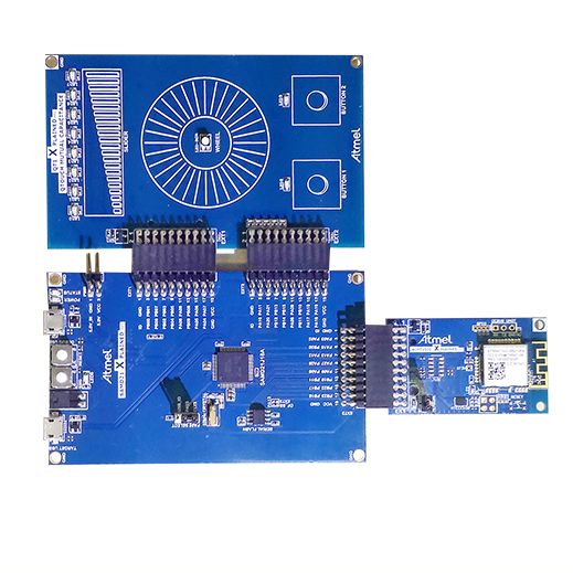
But instead of the usual blinking of the LED on debugging, we decided to blink lights at our office through a Wi-Fi network using the industrial ModBus TCP protocol for greater scale, and we will manage it using touch buttons and sliders. We will already use the SAMD21 Xplained Pro debug card for our readers, with 2 ATWINC1500-XPRO and ATQT1-XPRO expansion modules connected to it. Having connected expansion modules to debugging we get the following construction:
A bit about debugging a series of Xplained Pro
Xplained Pro Kits is a series of mid-priced debugging boards (the cheapest are the Xplained mini whales) for various Atmel microcontroller families and a set of expansion modules for them. Moreover, due to the unified edge connectors on the debugs, the expansion modules fit any board. Those. implemented the concept a la Arduino. All boards have an EDBG debugger installed. The rest of the peripherals on the board depends on the controller installed on it.
Formulation of the problem
In our office, we installed LED controlled (read dimmable) lamps using the DALI protocol. For communication with the outside world, the lighting system uses the ModBus-DALI gateway of our design. The gateway can be controlled both via RS485 interface (ModBus RTU) and via Ethernet (ModBus TCP). To solve our problem we will use the latter. Thus, our design connects to the local network via Wi-Fi, the microcontroller analyzes the state of the touch buttons and slider and converts them into ModBus TCP protocol commands. Those, in turn, are converted into DALI commands and are sent to the performance of lamps.
Note: ModBus DALI gateway is not an object of description in this series of articles, but is taken as a given and the only way to integrate into the lighting control system (SLA).
Connecting Wi-Fi module WINC1500
Atmel, like many other manufacturers of semiconductor technology, is trying to find a cushy place in the incomprehensible, but gaining strength and popularity of the financial “bubble” called Internet Of Things. Therefore, Atmel positions its Wi-Fi solutions as low-consuming and designed for use in Internet of things devices. The WINC1500 module considered in today's article is designed to work with a host controller via a serial interface UART / SPI / I2C. The module has a chip antenna on board.
Summary of datasheet
- IEEE802.11 b / g / n 20MHz (1x1) solution
- 2.4 GHz ISM band
- Integrated PA and T / R Switch
- Integrated PCB antenna
- PHY signal processing
- Advanced Equalization and Channel Estimation
- Advanced Carrier and Timing Synchronization
- Wi-Fi Direct and Soft-AP support
- Supports IEEE 802.11 WEP, WPA, WPA2 Security
- Supports China WAPI security
- Superior MAC throughput hardware frame two-level A-MSDU / A-MPDU frame aggregation and block acknowledgment
- On-chip memory management engine to reduce host load
- SPI, UART, and I2C host interfaces
- 2- or 3-wire Bluetooth coexistence interface
- Operating temperature range -40 ° C to + 85 ° C
- I / O operating voltage of 2.7V to 3.6V
- Integrated Flash memory for system software
- Power Save Modes
- Integrated Network IP stack to minimize host CPU requirements
- Network features TCP, UDP, DHCP, ARP, HTTP, SSL, and DNS
- Small footprint host driver (4KB flash - less than 1KB RAM)
')
Connection of the expansion module to debugging and pre-setting
Debugging SAMD21 Xplained has 3 external connectors for connecting expansion cards. By default, the project is created on the assumption that the expansion card with the WINC1500 is connected to the debugging connector EXT1. If you need to connect it to another connector, you need to change ports in the conf_winc.h file:
Defaults for using EXT3
// ---------- PIN settings --------- #define CONF_WINC_PIN_RESET PIN_PA27 #define CONF_WINC_PIN_CHIP_ENABLE PIN_PA28 #define CONF_WINC_PIN_WAKE PIN_PB08 // ---------- SPI settings --------- #define CONF_WINC_USE_SPI (1) /** SPI pin and instance settings. */ #define CONF_WINC_SPI_MODULE SERCOM2 #define CONF_WINC_SPI_SERCOM_MUX SPI_SIGNAL_MUX_SETTING_D #define CONF_WINC_SPI_PINMUX_PAD0 PINMUX_PA12C_SERCOM2_PAD0 /* out */ #define CONF_WINC_SPI_PINMUX_PAD1 PINMUX_PA13C_SERCOM2_PAD1 /* sck */ #define CONF_WINC_SPI_PINMUX_PAD2 PINMUX_UNUSED /* cs driven from software */ #define CONF_WINC_SPI_PINMUX_PAD3 PINMUX_PA15C_SERCOM2_PAD3 /* in */ #define CONF_WINC_SPI_CS_PIN PIN_PA14 /** SPI interrupt pin. */ #define CONF_WINC_SPI_INT_PIN PIN_PB09A_EIC_EXTINT9 #define CONF_WINC_SPI_INT_MUX MUX_PB09A_EIC_EXTINT9 #define CONF_WINC_SPI_INT_EIC (9) The module is connected to the host controller at SPI debugging, in addition to the module there is an input / output port, which the module “pulls” at any event (receiving / sending a packet). In the code, a hardware interrupt is configured when the level on this pin changes. When an interrupt occurs in the handler, the event counter increases.
Setting debazh output to COM port
The built-in EDBG debugger is defined in the device manager as a debugger and as a virtual COM-port, to which you can configure one of the microcontroller SERCOMs. Thus, you can output debugging messages to the COM port through the same USB-micro connector, through which programming and debugging takes place:
Initialization function code
static void configure_console(void) { struct usart_config usart_conf; usart_get_config_defaults(&usart_conf); usart_conf.mux_setting = EDBG_CDC_SERCOM_MUX_SETTING; usart_conf.pinmux_pad0 = EDBG_CDC_SERCOM_PINMUX_PAD0; usart_conf.pinmux_pad1 = EDBG_CDC_SERCOM_PINMUX_PAD1; usart_conf.pinmux_pad2 = EDBG_CDC_SERCOM_PINMUX_PAD2; usart_conf.pinmux_pad3 = EDBG_CDC_SERCOM_PINMUX_PAD3; usart_conf.baudrate = 115200; stdio_serial_init(&cdc_uart_module, EDBG_CDC_MODULE, &usart_conf); usart_enable(&cdc_uart_module); } Callback'and our all
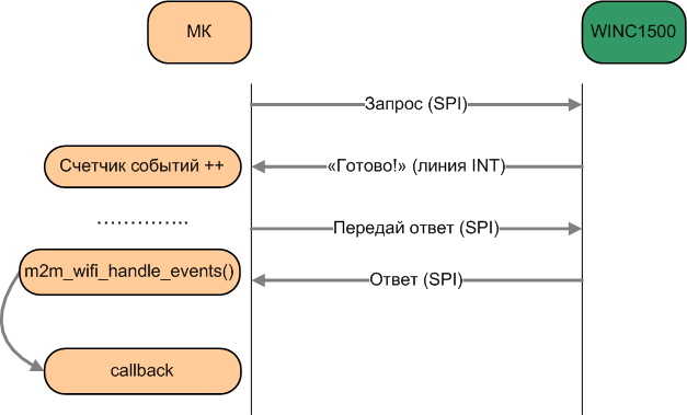
The library for working with the WINC1500 module is built on the principle of Callbacks, i.e. if we want something from the module (for example, to get the number of available Wi-Fi networks on the radio), then we call the corresponding function (which sends the necessary request to the module) and the module leaves to “think”. When the module generates the result, it will change the state of the INT pin, thereby triggering an external interrupt in the microcontroller, the handler of which increases the event counter. When you call the function m2m_wifi_handle_events (NULL); the number of events and parameters (type, required data) of each event (in our example, the termination of the air scan and the readiness to return the number of found networks) are read, and the corresponding function (Callback) is called if it is initialized and registered in advance.
Verify connectivity with WINC1500 over SPI
To get started, you need to initialize the module, configure and register the necessary Callbacks. To read the parameters of the module callback is not needed, so as long as we do not register and do not.
Initializing the module and getting its parameters
int main(void) { tstrWifiInitParam settings; int8_t ret; // Initialize the board. system_init(); // Initialize the UART console. configure_console(); printf(STRING_HEADER); // Initialize the BSP. nm_bsp_init(); // Initialize Wi-Fi parameters structure. memset((uint8_t *)&settings, 0, sizeof(tstrWifiInitParam)); //Initialize Wi-Fi driver with data and status callbacks. ret = m2m_wifi_init(&settings); if (M2M_SUCCESS != ret) { printf("main: m2m_wifi_init call error!(%d)\r\n", ret); while (1); } // Display WINC1500 chip information. printf("Chip ID : \r\t\t\t%x\r\n", (unsigned int)nmi_get_chipid()); printf("RF Revision ID : \r\t\t\t%x\r\n", (unsigned int)nmi_get_rfrevid()); printf("Done.\r\n\r\n"); while (1); return 0; } Creating an access point
WINC1500 allows you to create an access point and distribute IP addresses to connected subscribers via DHCP. The beginning of main is the same as in the previous example, but it adds initialization of the structure containing the parameters of the access point and the creation of an access point, as well as registering the callback before initializing the module:
// Initialize Wi-Fi parameters structure. memset((uint8_t *)&settings, 0, sizeof(tstrWifiInitParam)); // Initialize Wi-Fi driver with data and status callbacks. settings.pfAppWifiCb = wifi_cb; ret = m2m_wifi_init(&settings); if (M2M_SUCCESS != ret) { printf("main: m2m_wifi_init call error!(%d)\r\n", ret); while (1); } In access point mode, the WINC1500 supports only WEP encryption (WPA is not supported) or an open Wi-Fi network. Also only 1 client is supported.
Creating an access point. Additional code
Main function code:
// Initialize AP mode parameters structure with SSID, channel and OPEN security type. memset(&strM2MAPConfig, 0x00, sizeof(tstrM2MAPConfig)); strcpy((char *)&strM2MAPConfig.au8SSID, MAIN_WLAN_SSID); strM2MAPConfig.u8ListenChannel = MAIN_WLAN_CHANNEL; strM2MAPConfig.u8SecType = MAIN_WLAN_AUTH; strM2MAPConfig.au8DHCPServerIP[0] = 192; strM2MAPConfig.au8DHCPServerIP[1] = 168; strM2MAPConfig.au8DHCPServerIP[2] = 1; strM2MAPConfig.au8DHCPServerIP[3] = 1; #if USE_WEP strcpy((char *)&strM2MAPConfig.au8WepKey, MAIN_WLAN_WEP_KEY); strM2MAPConfig.u8KeySz = strlen(MAIN_WLAN_WEP_KEY); strM2MAPConfig.u8KeyIndx = MAIN_WLAN_WEP_KEY_INDEX; #endif /* Bring up AP mode with parameters structure. */ ret = m2m_wifi_enable_ap(&strM2MAPConfig); if (M2M_SUCCESS != ret) { printf("main: m2m_wifi_enable_ap call error!\r\n"); while (1); } printf("AP mode started. You can connect to %s.\r\n", (char *)MAIN_WLAN_SSID); while (1) { while (m2m_wifi_handle_events(NULL) != M2M_SUCCESS); // Handle pending events from network controller. } // callback static void wifi_cb(uint8_t u8MsgType, void *pvMsg) { switch (u8MsgType) { case M2M_WIFI_RESP_CON_STATE_CHANGED: { tstrM2mWifiStateChanged *pstrWifiState = (tstrM2mWifiStateChanged *)pvMsg; if (pstrWifiState->u8CurrState == M2M_WIFI_CONNECTED) { } else if (pstrWifiState->u8CurrState == M2M_WIFI_DISCONNECTED) { printf("Station disconnected\r\n"); } break; } case M2M_WIFI_REQ_DHCP_CONF: { uint8_t *pu8IPAddress = (uint8_t *)pvMsg; printf("Station connected\r\n"); printf("Station IP is %u.%u.%u.%u\r\n", pu8IPAddress[0], pu8IPAddress[1], pu8IPAddress[2], pu8IPAddress[3]); break; } default: { break; } } } main.h: /** Security mode */ #define USE_WEP (1) /*< Set to (1) to use WEP, and (0) to use OPEN */ /** AP mode Settings */ #define MAIN_WLAN_SSID "WINC1500_AP" /* < SSID */ #if USE_WEP #define MAIN_WLAN_AUTH M2M_WIFI_SEC_WEP /* < Security manner */ #define MAIN_WLAN_WEP_KEY "1234567890" /* < Security Key in WEP Mode */ #define MAIN_WLAN_WEP_KEY_INDEX (1) #else #define MAIN_WLAN_AUTH M2M_WIFI_SEC_OPEN /* < Security manner */ #endif #define MAIN_WLAN_CHANNEL (6) /* < Channel number */ Work in the access point mode, due to the voiced restrictions, is not the main mode of operation of the WINC1500, but serves mainly to implement a mechanism for connecting to a third-party access point. For example, if your device does not have an interface in order to set the network parameters (SSID and password) to which you want to connect, you can first create your own access point and connect to it in some way to transfer data about the target network.
By the way, this mechanism is already implemented in the module: by a special command, in addition to starting your own access point, you can start the WEB server built into the module and connect to it with a browser to set the connection parameters to the target network.
Get a list of available networks
Now let's scan the air for Wi-Fi networks and list them in the debug port.
To start scanning, it is enough to call the function m2m_wifi_request_scan (M2M_WIFI_CH_ALL) immediately after the module initialization
/* Initialize Wi-Fi parameters structure. */ memset((uint8_t *)&settings, 0, sizeof(tstrWifiInitParam)); /* Initialize Wi-Fi driver with data and status callbacks. */ settings.pfAppWifiCb = wifi_cb; ret = m2m_wifi_init(&settings); if (M2M_SUCCESS != ret) { printf("main: m2m_wifi_init call error!(%d)\r\n", ret); while (1); } /* Request scan. */ m2m_wifi_request_scan(M2M_WIFI_CH_ALL); But at the same time, it is necessary to provide for the appropriate processing of scan events in the callback wifi_cb
Wifi_cb code to scan
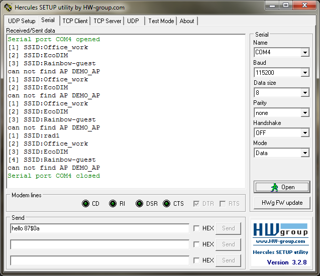
static void wifi_cb(uint8_t u8MsgType, void *pvMsg) { switch (u8MsgType) { case M2M_WIFI_RESP_SCAN_DONE: { tstrM2mScanDone *pstrInfo = (tstrM2mScanDone *)pvMsg; scan_request_index = 0; if (pstrInfo->u8NumofCh >= 1) { m2m_wifi_req_scan_result(scan_request_index); scan_request_index++; } else { m2m_wifi_request_scan(M2M_WIFI_CH_ALL); } break; } case M2M_WIFI_RESP_SCAN_RESULT: { tstrM2mWifiscanResult *pstrScanResult = (tstrM2mWifiscanResult *)pvMsg; uint16_t demo_ssid_len; uint16_t scan_ssid_len = strlen((const char *)pstrScanResult->au8SSID); /* display founded AP. */ printf("[%d] SSID:%s\r\n", scan_request_index, pstrScanResult->au8SSID); num_founded_ap = m2m_wifi_get_num_ap_found(); if (scan_ssid_len) { /* check same SSID. */ demo_ssid_len = strlen((const char *)MAIN_WLAN_SSID); if( (demo_ssid_len == scan_ssid_len) && (!memcmp(pstrScanResult->au8SSID, (uint8_t *)MAIN_WLAN_SSID, demo_ssid_len))) { /* A scan result matches an entry in the preferred AP List. * Initiate a connection request. */ printf("Found %s \r\n", MAIN_WLAN_SSID); m2m_wifi_connect((char *)MAIN_WLAN_SSID,sizeof(MAIN_WLAN_SSID), MAIN_WLAN_AUTH,(void *)MAIN_WLAN_PSK,M2M_WIFI_CH_ALL); break; } } if (scan_request_index < num_founded_ap) { m2m_wifi_req_scan_result(scan_request_index); scan_request_index++; } else { printf("can not find AP %s\r\n", MAIN_WLAN_SSID); m2m_wifi_request_scan(M2M_WIFI_CH_ALL); } break; } case M2M_WIFI_RESP_CON_STATE_CHANGED: { tstrM2mWifiStateChanged *pstrWifiState = (tstrM2mWifiStateChanged *)pvMsg; if (pstrWifiState->u8CurrState == M2M_WIFI_CONNECTED) { m2m_wifi_request_dhcp_client(); } else if (pstrWifiState->u8CurrState == M2M_WIFI_DISCONNECTED) { printf("Wi-Fi disconnected\r\n"); /* Request scan. */ m2m_wifi_request_scan(M2M_WIFI_CH_ALL); } break; } case M2M_WIFI_REQ_DHCP_CONF: { uint8_t *pu8IPAddress = (uint8_t *)pvMsg; printf("Wi-Fi connected\r\n"); printf("Wi-Fi IP is %u.%u.%u.%u\r\n", pu8IPAddress[0], pu8IPAddress[1], pu8IPAddress[2], pu8IPAddress[3]); break; } default: { break; } } } To debug connection and data transfer via UDP / TCP and debug in general is very convenient with Hercules)
The debug output of the scan result is:
DHCP connection
By default, WINC connects via DHCP, and by hints in various Atmel comments and documents, they want to shut off the ability to connect with a static IP.
When connected via DHCP, the callback code must handle the corresponding event.
Wifi_cb code when using DHCP
static void wifi_cb(uint8_t u8MsgType, void *pvMsg) { switch (u8MsgType) { case M2M_WIFI_RESP_CON_STATE_CHANGED: { tstrM2mWifiStateChanged *pstrWifiState = (tstrM2mWifiStateChanged *)pvMsg; if (pstrWifiState->u8CurrState == M2M_WIFI_CONNECTED) { printf("wifi_cb: M2M_WIFI_RESP_CON_STATE_CHANGED: CONNECTED\r\n"); m2m_wifi_request_dhcp_client(); } else if (pstrWifiState->u8CurrState == M2M_WIFI_DISCONNECTED) { printf("wifi_cb: M2M_WIFI_RESP_CON_STATE_CHANGED: DISCONNECTED\r\n"); wifi_connected = 0; m2m_wifi_connect((char *)MAIN_WLAN_SSID, sizeof(MAIN_WLAN_SSID), MAIN_WLAN_AUTH, (char *)MAIN_WLAN_PSK, M2M_WIFI_CH_ALL); } break; } case M2M_WIFI_REQ_DHCP_CONF: { uint8_t *pu8IPAddress = (uint8_t *)pvMsg; wifi_connected = 1; printf("wifi_cb: M2M_WIFI_REQ_DHCP_CONF: IP is %u.%u.%u.%u\r\n",pu8IPAddress[0], pu8IPAddress[1], pu8IPAddress[2], pu8IPAddress[3]); break; } default: { break; } } } Connection with a static address
To connect with a static address, you must first disable the automatic dhcp connection in main after the module is initialized:
m2m_wifi_enable_dhcp(0); And change the callback accordingly:
Wifi_cb code when using static IP
static void wifi_cb(uint8_t u8MsgType, void *pvMsg) { printf("wifi_cb: u8MsgType= %d\n",u8MsgType); switch (u8MsgType) { case M2M_WIFI_RESP_CON_STATE_CHANGED: { tstrM2mWifiStateChanged *pstrWifiState = (tstrM2mWifiStateChanged *)pvMsg; if (pstrWifiState->u8CurrState == M2M_WIFI_CONNECTED) { printf("wifi_cb: M2M_WIFI_RESP_CON_STATE_CHANGED: CONNECTED\r\n"); tstrM2MIPConfig ip_client; ip_client.u32StaticIP = _htonl(0xc0a8142d); //corresponds to 192.168.20.45 ip_client.u32DNS = _htonl(0xc0a80266); //corresponds to 192.168.2.102 ip_client.u32SubnetMask =_htonl(0xFFFFFF00); //corresponds to 255.255.255.0 ip_client.u32Gateway = _htonl(0xc0a81401); //corresponds to 192.168.20.1 m2m_wifi_set_static_ip(&ip_client); wifi_connected = 1; } else { if (pstrWifiState->u8CurrState == M2M_WIFI_DISCONNECTED) { printf("wifi_cb: M2M_WIFI_RESP_CON_STATE_CHANGED: DISCONNECTED\r\n"); wifi_connected = 0; m2m_wifi_connect((char *)MAIN_WLAN_SSID, sizeof(MAIN_WLAN_SSID), MAIN_WLAN_AUTH, (char *)MAIN_WLAN_PSK, M2M_WIFI_CH_ALL); } } break; } default: break; } } Work with TCP / IP stack
Most APIs for working with the TCP / IP stack through the WINC1500 are implemented by analogy with Berkeley sockets.
| Berkeley API | WINC API | Server / Client | TCP / UDP | Description |
|---|---|---|---|---|
| socket | socket | Both | Both | Creates a new socket |
| connect | connect | Client | Tcp | Establishes a TCP connection to a remote server. |
| bind | bind | Server | Both | Bindit socket with IP address and port |
| listen | listen | Server | Tcp | Creates a TCP server |
| send | send | Both | Both | Send data to socket |
| sendto | sendto | Both | UDP | Sends packet over UDP |
| recv | recv | Both | Both | Receives a packet |
| recvfrom | recvfrom | Both | Both | Receives a packet |
| close | close | Both | Both | Closes connection and frees up resources. |
| gethostbyname | gethostbyname | Both | Both | Gets the IP address by host name |
| setsockopt | setsockopt | Both | Both | Sets socket options |
| htons / ntohs | htons / ntohs | Both | Both | Changes the byte order in 2-byte integers from the host representation to the network and vice versa. |
| htonl / ntohl | htonl / ntohl | Both | Both | Changes the byte order in 4-byte integers from the host representation to the network and vice versa. |
UDP and TCP
To work on UDP and TCP, it is necessary to create the corresponding sockets, initialize them, open, write and register a callback for processing the reception / transmission of data. We will not dwell on each case in detail (UDP sending / receiving, TCP client / server), consider the main points.
The initialization of socket parameters is accomplished using an appropriate structure. It is necessary to specify the type of connection, port, server IP (in the form of 0xc0a814ff, for example, for 192.168.20.255)
struct sockaddr_in src_addr; addr.sin_family = AF_INET; addr.sin_port = _htons(MAIN_WIFI_M2M_SERVER_PORT); addr.sin_addr.s_addr = _htonl(MAIN_WIFI_M2M_SERVER_IP); We initialize the socket and callback to it, and also connect to the network with the previously specified parameters in the addr structure:
socketInit(); registerSocketCallback(socket_cb, NULL); // Connect to router. m2m_wifi_connect((char *)MAIN_WLAN_SSID, sizeof(MAIN_WLAN_SSID), MAIN_WLAN_AUTH, (char *)MAIN_WLAN_PSK, M2M_WIFI_CH_ALL); printf("m2m_wifi_connect!\r\n"); In the main loop, we create a socket and bind it and implement connection support (in case of disconnection, reconnection). Both for UDP and TCP, the procedures are the same except for the connection type (SOCK_DGRAM UDP, SOCK_STREAM TCP).
SOCKET rx_socket = -1; while(1): if (rx_socket < 0) { if ((rx_socket = socket(AF_INET, SOCK_DGRAM, 0)) < 0) { printf("main: failed to create RX UDP Client socket error!\r\n"); continue; } // Socket bind bind(rx_socket, (struct sockaddr *)&src_addr, sizeof(struct sockaddr_in)); } if (wifi_connected == M2M_WIFI_CONNECTED) { // Open client socket. if (rx_socket < 0) { if ((rx_socket = socket(AF_INET, SOCK_STREAM, 0)) < 0) { printf("main: failed to create TCP client socket error!\r\n"); continue; } // Connect server printf("socket_number new connection: %d\r\n", rx_socket); ret=connect(rx_socket, (struct sockaddr *)&addr, sizeof(struct sockaddr_in)); printf("ret value: %d\r\n", ret); connected = FALSE; if (ret < 0) { close(rx_socket); rx_socket = -1; } } } The callback should handle the connection / bind, receive, and transfer events for the TCP server: listen, accept.
An example callback for simultaneous operation of UDP (rx_socket) and TCP (tcp_client_socket):
socket_cb for UDP and TCP
static void socket_cb(SOCKET sock, uint8_t u8Msg, void *pvMsg) { // Check for socket event on RX socket. if (sock == rx_socket) { if (u8Msg == SOCKET_MSG_BIND) { tstrSocketBindMsg *pstrBind = (tstrSocketBindMsg *)pvMsg; if (pstrBind && pstrBind->status == 0) { // Prepare next buffer reception. sock_bind_state = 1; recv(sock, udp_data_rx, MAIN_WIFI_M2M_BUFFER_SIZE, 0); } else { printf("socket_cb: bind error!\r\n"); } } else if (u8Msg == SOCKET_MSG_RECVFROM) { tstrSocketRecvMsg *pstrRx = (tstrSocketRecvMsg *)pvMsg; if (pstrRx->pu8Buffer && pstrRx->s16BufferSize) { delay = 0; sock_rx_state = pstrRx->s16BufferSize; printf("socket_cb udp recv!\r\n"); printf("rx packet length= %d\n",pstrRx->s16BufferSize); } else { if (pstrRx->s16BufferSize == SOCK_ERR_TIMEOUT) { // Prepare next buffer reception. recv(sock, udp_data_rx, MAIN_WIFI_M2M_BUFFER_SIZE, 0); } } } if (u8Msg == SOCKET_MSG_SENDTO) { recv(sock, udp_data_rx, MAIN_WIFI_M2M_BUFFER_SIZE, 0); sock_tx_state = 1; } } if (sock == tcp_client_socket) { switch (u8Msg) { // Socket connected case SOCKET_MSG_CONNECT: { tstrSocketConnectMsg *pstrConnect = (tstrSocketConnectMsg *)pvMsg; if (pstrConnect && pstrConnect->s8Error >= 0) { printf("socket_cb tcp connect!\r\n"); tcp_ready_to_send=1; } else { close(tcp_client_socket); tcp_client_socket = -1; } } break; // Message send case SOCKET_MSG_SEND: { printf("socket_cb tcp send!\r\n"); recv(tcp_client_socket, tcp_data_rx, sizeof(tcp_data_rx), 0); tcp_tx_ready=1; } break; // Message receive case SOCKET_MSG_RECV: { tstrSocketRecvMsg *pstrRecv = (tstrSocketRecvMsg *)pvMsg; if (pstrRecv && pstrRecv->s16BufferSize > 0) { tcp_rx_ready=pstrRecv->s16BufferSize; } else { close(tcp_client_socket); tcp_client_socket = -1; } } break; default: break; } } } It is important not to forget to call the event handling function from the module in while (1):
m2m_wifi_handle_events(NULL); Conclusion
Now, using the knowledge gained, we can already connect over the local network to our ModBus-DALI gateway. The gateway is a TCP server on port 502. But about this in the third part of the cycle, which we devote to the implementation of the ModBus TCP protocol on top of our local network. In the second part, we will consider connecting and using touch buttons as a control interface. Until new meetings.
Source: https://habr.com/ru/post/275359/
All Articles