Measuring the weight of minerals in the mining industry. Theoretical basis
In the mining industry, many vehicles will be used to transport minerals from the mine to the surface. These are self-propelled installations, inclined congresses with cars, mine elevating installations (silos or silos ). Here we will talk about MOP.
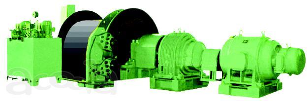
They are of different types, both according to the used lifting vessels (skip, crate, tub), and the number of suspended lifting vessels (single-ended, two-terminal). A lot of nuances there, in terms of mechanics. You can see the description here and here .
')
Drives, too, are different. DC and AC. For alternating current it can be high-voltage asynchronous motors with a phase-rotor, synchronous motors, low-voltage asynchronous motors with a short-circuited rotor. Let's talk about silos with a high-voltage asynchronous motor with a phase-rotor.
In all enterprises where mining takes place, the main indicator of a company's success is the amount of ore mined. In modern activities, measuring the weight of mined ore is carried out in a variety of ways. Weighing of road transport during transportation from the place of extraction to the place of processing or storage, railway cars, if used, etc. All this has a place to be. But such systems are expensive in terms of capital costs. And what if we weigh the weight of the raised ore at the stage of its transportation in a lifting vessel? Quite possible.
The mass of the load transported by the lifting vessel is determined by the moment of the lifting engine or the force developed by the engine on the circumference of the traction driver. The measurement is performed on a straight section, at a constant engine speed. At this time, the force F on a circle of radius R is equal to the sum of the efforts required to transport a load of mass Mgr, as well as to overcome the forces of mine resistance Fm and the forces of static unbalance Fst of the lifting and lowering branches of the lifting installation

Where, g is the acceleration of gravity, i is the gear ratio of the gearbox.
Since at the point of "weighing" when moving with one and the same speed, the mine resistance forces and the initial difference of static forces remain unchanged, then to calculate the mass of the lifted load it is necessary to subtract the constants Fsh and Fst from the measured effort F.
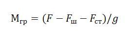
The constants Fsh and Fst can be calculated at the start-up phase, for each specific rise. To do this, it is enough to raise an empty vessel and measure the force developed by the engine, and then take it away from the force of lifting the load.
Also, on any lifting installation, except for the initial static imbalance, due to ore sticking to the vessel walls, wear of the vessel lining there is a variable component F per, which varies from cycle to cycle. At the double-end hoisting installations, Fper though distorts the calculation of the mass of the load compared to the actual, but has practically no effect on the calculation of the total mass after several lifting cycles. Since the remaining ore in one vessel will be subtracted from the mass of the newly lifted load in the other vessel.
If the installation is with a vessel and a counterweight, then at the measurement stage, to minimize the influence of the variable component, the following occurs. During the lowering of the empty vessel and the raising of the counterweight, the force developed by the engine is measured, it will differ from the force during calibration by the amount of lining stuck on the vessel and wear. And when lifting a vessel, the difference of forces must be subtracted from the force, thereby compensating for the variable component.
The force F developed by the AC motor on the circumference of the winding with radius R is determined by:
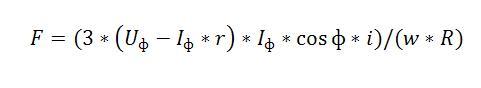
Where:
This formula is valid for a symmetrical load, which a serviceable electric motor is.
The signal proportional to the current is removed from the secondary winding of the current transformer, having a standard current output of 0-5A. A voltage proportional signal from a voltage transformer.
To measure the phase voltage of the motor, it is necessary to install a phase voltage transformer, that is, with the characteristic 6000 / √3 to 100 / √3 volts. This is an additional expense. Current and voltage transformers have already been installed in the high-voltage motor control cell. True voltage transformer measures linear voltage with a characteristic of 6000 to 100 volts.
Having two signals, current and voltage, it is easy to calculate the other values.
The effective values of current and voltage of one phase of three phase voltages in MK can be calculated by the following formula.
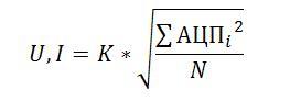
Where:
The active power of one phase is calculated by the formula.

Where:
Further, for the calculation it is necessary to calculate the cosine phi.

The remaining variables in the formula for calculating the force developed by the engine are constants.
Since a linear voltage transformer is installed in the high-voltage cell, the formula for the force can be rewritten taking into account the linear voltage. It will take the following form:

But if we have signals of phase current and line voltage, the active power will not be calculated, as is cosine phi, and cosine is, along with the effective values of voltage and current, the main variable in the equation. The cosine phi will vary widely while the engine is running.
There are several solutions to this problem, as always.
We will go the second way.
Typical voltage transformers are shown in the figure.

Three Phase Voltage Chart:
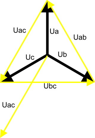
The angle between the phase voltage Uv and linear Uac is -90 °. The voltage of the secondary winding of the voltage transformer is 100 Volts of current voltage, that is, 141 Volts in amplitude. In this form, the MK will not drive. We'll have to scale.
Well, the linear voltage phase is necessary to make it lag by 90 ° so that it coincides with phase B. This can be helped by the ordinary first-order low-pass filter - the RC chain.
The main characteristics of the RC circuit.
Gear ratio:

Phase Shift Angle:

Since the angle is with a minus sign, this means that the phase of the output voltage is lagging behind the phase of the input by an angle.
When using the usual RC circuit, we "kill two birds with one stone". Coefficient of scaling the signal within a couple of volts, for processing in MK. And having a phase shift close to 90 °, the phase of the sinusoid after the RC circuit coincides with the phase B, which includes the current transformer. Consequently, all calculations of the force developed by the engine would be valid if we used the phase current and voltage.
Calculate the values of R and C for our case.
From the voltage transformer comes 100 volts voltage (standard). This is the effective voltage, therefore, in order for us to determine the amplitude value we multiply by the root of 2.
TOTAL: Umax = U * 1.41 = 141V.
It is a sine wave, and it has both a positive half-wave and a negative one. So, for MK, we need to insert this sine wave into positive unipolar voltage.
Power supply MK take 3 c. This means that the midpoint for a sine wave will be 1.5 volts. Total span of a half-wave of voltage remains to us 1.5 volts. From here the transmission ratio of the RC circuit will be:

Now we calculate the value τ = RC, based on the coefficient K. The signal frequency is known - 50 Hz.
After mathematical transformations, we obtain: τ = RC = 0.318.
From here

The corner suits us. We calculate the measurement error, with a phase error of 0.57 °, hence the error is: (0.57 ° / 90 °) * 100% = 0.63%, this is for a quarter of the period, therefore for 360 ° and even less. Hardly current and voltage transformers will be an accuracy class higher than 0.5%. So, the distortions introduced by our filter can be neglected.
It remains to calculate the values of R and C themselves. It is better to push off from the capacitor. Take = 4.7 microfarad, from here R = τ / = 0.318 / 4.7 * 10-6 = 318 * 10-3 / 4.7 * 10-6 = 67.66 * 103 Ohms or 67.66 kOhm .
The value of the resistor is worth taking more than 10 kOhm so that we can measure the voltage a little more than 6000 volts, where this value may be less, somewhere more volt by 400-500. In addition, the angle φ will increase slightly, which will increase the accuracy of calculations.
The current sensor in our circuit will be an integrated circuit ACS712ELCTR-05B-T, here is its pdf . Our primary device is a current transformer with an output characteristic of 0-5 A. You can of course load it onto a shunt of small resistance and then through the opamp, adjust the scale to the required limits. In terms of cost, this is not much cheaper development. And if we apply the ACS712, we also get a galvanic isolation in 2.1 kVRMS. Also a tangible plus.
From the voltage transformer you can take the signal directly and feed it to the RC chain for further processing. But you can also untie galvanically, because the cable line from the primary devices to the device can be a decent length. Here you can use a linear transformer of not high power with a transfer ratio of 1: 1. You can use another one as long as the output voltage meets the condition for obtaining the required error in the phase shift and amplitude after the RC filter. Calculations of R and C for such inclusion are given above.
All these signals after the initial processing and normalization of the values can be driven into the MC and make calculations based on the information received. And to display it already to someone as convenient and necessary. To equip the device with some kind of interface and transfer the data to the lift control system, for example. Fantasy in this regard is almost limitless.
Here is an approximate scheme turned out.
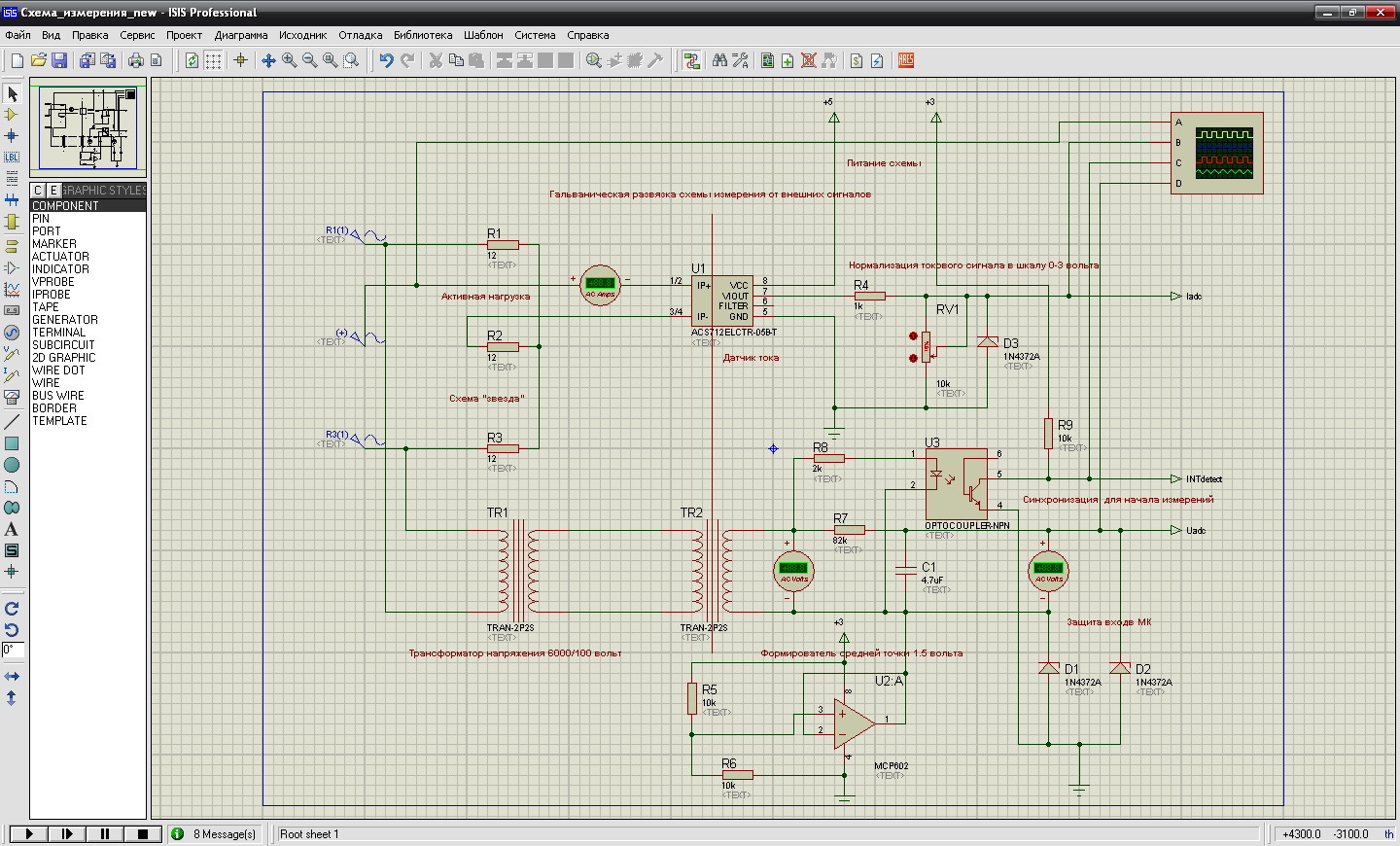 The picture is clickable.
The use of an optocoupler in this case is determined by synchronizing the start of the measurement from a single starting point. In this switching on, the output of the optocoupler will detect the positive half-wave of the line voltage Uac, that is, when the voltage after the RC circuit is at its maximum. Someone will say that the error of voltage measurement for the period will be born here. But since we always begin to measure it at the same point of the sinusoid, even if it is not at zero, and to take measurements of several periods, this time can be corrected by a factor. The same principle applies to current.
Now, using formulas for calculating the effective values of current, voltage and calculation of active power, it is possible to calculate the necessary variables for calculating the mass. The remaining constants in the equation are a feature of each silo.
In conclusion, a short video demonstrating the possibilities of this scheme.
The archive with the proteus project is here .
Measurement of ore weight by stator current. Practice. Part 1. Signal processing algorithm in MK
They are of different types, both according to the used lifting vessels (skip, crate, tub), and the number of suspended lifting vessels (single-ended, two-terminal). A lot of nuances there, in terms of mechanics. You can see the description here and here .
')
Drives, too, are different. DC and AC. For alternating current it can be high-voltage asynchronous motors with a phase-rotor, synchronous motors, low-voltage asynchronous motors with a short-circuited rotor. Let's talk about silos with a high-voltage asynchronous motor with a phase-rotor.
Introduction
In all enterprises where mining takes place, the main indicator of a company's success is the amount of ore mined. In modern activities, measuring the weight of mined ore is carried out in a variety of ways. Weighing of road transport during transportation from the place of extraction to the place of processing or storage, railway cars, if used, etc. All this has a place to be. But such systems are expensive in terms of capital costs. And what if we weigh the weight of the raised ore at the stage of its transportation in a lifting vessel? Quite possible.
Not a lot of theory and formulas
The mass of the load transported by the lifting vessel is determined by the moment of the lifting engine or the force developed by the engine on the circumference of the traction driver. The measurement is performed on a straight section, at a constant engine speed. At this time, the force F on a circle of radius R is equal to the sum of the efforts required to transport a load of mass Mgr, as well as to overcome the forces of mine resistance Fm and the forces of static unbalance Fst of the lifting and lowering branches of the lifting installation
Where, g is the acceleration of gravity, i is the gear ratio of the gearbox.
Since at the point of "weighing" when moving with one and the same speed, the mine resistance forces and the initial difference of static forces remain unchanged, then to calculate the mass of the lifted load it is necessary to subtract the constants Fsh and Fst from the measured effort F.
The constants Fsh and Fst can be calculated at the start-up phase, for each specific rise. To do this, it is enough to raise an empty vessel and measure the force developed by the engine, and then take it away from the force of lifting the load.
Lyrical digression
With such a measurement of the mass of ore, jeweler's accuracy cannot be achieved. And for commercial accounting, the error will be too big. According to rough estimates, it will be around 2-3%. But for technological accounting, this error is acceptable. The advantage of this method lies in the simplicity and low cost of the device, in which there are no mechanical, critical nodes (strain gauges, frame structures, etc., used in other weighing systems).
Also, on any lifting installation, except for the initial static imbalance, due to ore sticking to the vessel walls, wear of the vessel lining there is a variable component F per, which varies from cycle to cycle. At the double-end hoisting installations, Fper though distorts the calculation of the mass of the load compared to the actual, but has practically no effect on the calculation of the total mass after several lifting cycles. Since the remaining ore in one vessel will be subtracted from the mass of the newly lifted load in the other vessel.
If the installation is with a vessel and a counterweight, then at the measurement stage, to minimize the influence of the variable component, the following occurs. During the lowering of the empty vessel and the raising of the counterweight, the force developed by the engine is measured, it will differ from the force during calibration by the amount of lining stuck on the vessel and wear. And when lifting a vessel, the difference of forces must be subtracted from the force, thereby compensating for the variable component.
Asynchronous motor
The force F developed by the AC motor on the circumference of the winding with radius R is determined by:
Where:
- Uph, If - phase voltages and motor phase current,
- f - the angle between voltage and current,
- w is the angular velocity (2 * P * n / 60, where n is the rotational speed of the rotor of the engine),
- r is the stator phase resistance together with the lead-in cable.
This formula is valid for a symmetrical load, which a serviceable electric motor is.
The signal proportional to the current is removed from the secondary winding of the current transformer, having a standard current output of 0-5A. A voltage proportional signal from a voltage transformer.
To measure the phase voltage of the motor, it is necessary to install a phase voltage transformer, that is, with the characteristic 6000 / √3 to 100 / √3 volts. This is an additional expense. Current and voltage transformers have already been installed in the high-voltage motor control cell. True voltage transformer measures linear voltage with a characteristic of 6000 to 100 volts.
Having two signals, current and voltage, it is easy to calculate the other values.
Signal processing in MK
The effective values of current and voltage of one phase of three phase voltages in MK can be calculated by the following formula.
Where:
- U, I - the effective value of voltage, current,
- ADC - instantaneous values of voltage, current measured by ADC,
- K - coefficient of generalization (transformation ratio, coefficient per ADC unit),
- N is the number of measurements for the period of the network frequency.
The active power of one phase is calculated by the formula.
Where:
- ui, ii - instantaneous values of voltage, current measured by ADC,
- N is the number of measurements for the period of the mains voltage,
- K - generalizing coefficient.
Further, for the calculation it is necessary to calculate the cosine phi.
The remaining variables in the formula for calculating the force developed by the engine are constants.
Since a linear voltage transformer is installed in the high-voltage cell, the formula for the force can be rewritten taking into account the linear voltage. It will take the following form:
But if we have signals of phase current and line voltage, the active power will not be calculated, as is cosine phi, and cosine is, along with the effective values of voltage and current, the main variable in the equation. The cosine phi will vary widely while the engine is running.
There are several solutions to this problem, as always.
- Install a phase voltage transformer in the same phase with an installed current transformer (additional costs, high voltage voltage transformers have specific installation requirements, etc.).
- Use a linear voltage transformer included in two adjacent phases. That is, the current transformer is switched on in phase B, and the voltage transformer is in phases A and C (basically, such a transformer is already in the high-voltage cell feeding the electric motor).
We will go the second way.
Remember electrical engineering
Typical voltage transformers are shown in the figure.
Three Phase Voltage Chart:
The angle between the phase voltage Uv and linear Uac is -90 °. The voltage of the secondary winding of the voltage transformer is 100 Volts of current voltage, that is, 141 Volts in amplitude. In this form, the MK will not drive. We'll have to scale.
Well, the linear voltage phase is necessary to make it lag by 90 ° so that it coincides with phase B. This can be helped by the ordinary first-order low-pass filter - the RC chain.
The main characteristics of the RC circuit.
Gear ratio:
Phase Shift Angle:
Since the angle is with a minus sign, this means that the phase of the output voltage is lagging behind the phase of the input by an angle.
When using the usual RC circuit, we "kill two birds with one stone". Coefficient of scaling the signal within a couple of volts, for processing in MK. And having a phase shift close to 90 °, the phase of the sinusoid after the RC circuit coincides with the phase B, which includes the current transformer. Consequently, all calculations of the force developed by the engine would be valid if we used the phase current and voltage.
Calculate the values of R and C for our case.
Filter calculation
From the voltage transformer comes 100 volts voltage (standard). This is the effective voltage, therefore, in order for us to determine the amplitude value we multiply by the root of 2.
TOTAL: Umax = U * 1.41 = 141V.
It is a sine wave, and it has both a positive half-wave and a negative one. So, for MK, we need to insert this sine wave into positive unipolar voltage.
Power supply MK take 3 c. This means that the midpoint for a sine wave will be 1.5 volts. Total span of a half-wave of voltage remains to us 1.5 volts. From here the transmission ratio of the RC circuit will be:
Now we calculate the value τ = RC, based on the coefficient K. The signal frequency is known - 50 Hz.
After mathematical transformations, we obtain: τ = RC = 0.318.
From here
The corner suits us. We calculate the measurement error, with a phase error of 0.57 °, hence the error is: (0.57 ° / 90 °) * 100% = 0.63%, this is for a quarter of the period, therefore for 360 ° and even less. Hardly current and voltage transformers will be an accuracy class higher than 0.5%. So, the distortions introduced by our filter can be neglected.
It remains to calculate the values of R and C themselves. It is better to push off from the capacitor. Take = 4.7 microfarad, from here R = τ / = 0.318 / 4.7 * 10-6 = 318 * 10-3 / 4.7 * 10-6 = 67.66 * 103 Ohms or 67.66 kOhm .
The value of the resistor is worth taking more than 10 kOhm so that we can measure the voltage a little more than 6000 volts, where this value may be less, somewhere more volt by 400-500. In addition, the angle φ will increase slightly, which will increase the accuracy of calculations.
Some circuitry
The current sensor in our circuit will be an integrated circuit ACS712ELCTR-05B-T, here is its pdf . Our primary device is a current transformer with an output characteristic of 0-5 A. You can of course load it onto a shunt of small resistance and then through the opamp, adjust the scale to the required limits. In terms of cost, this is not much cheaper development. And if we apply the ACS712, we also get a galvanic isolation in 2.1 kVRMS. Also a tangible plus.
From the voltage transformer you can take the signal directly and feed it to the RC chain for further processing. But you can also untie galvanically, because the cable line from the primary devices to the device can be a decent length. Here you can use a linear transformer of not high power with a transfer ratio of 1: 1. You can use another one as long as the output voltage meets the condition for obtaining the required error in the phase shift and amplitude after the RC filter. Calculations of R and C for such inclusion are given above.
All these signals after the initial processing and normalization of the values can be driven into the MC and make calculations based on the information received. And to display it already to someone as convenient and necessary. To equip the device with some kind of interface and transfer the data to the lift control system, for example. Fantasy in this regard is almost limitless.
Here is an approximate scheme turned out.
The picture is clickable.The use of an optocoupler in this case is determined by synchronizing the start of the measurement from a single starting point. In this switching on, the output of the optocoupler will detect the positive half-wave of the line voltage Uac, that is, when the voltage after the RC circuit is at its maximum. Someone will say that the error of voltage measurement for the period will be born here. But since we always begin to measure it at the same point of the sinusoid, even if it is not at zero, and to take measurements of several periods, this time can be corrected by a factor. The same principle applies to current.
Now, using formulas for calculating the effective values of current, voltage and calculation of active power, it is possible to calculate the necessary variables for calculating the mass. The remaining constants in the equation are a feature of each silo.
In conclusion, a short video demonstrating the possibilities of this scheme.
The archive with the proteus project is here .
PS
Continued:Measurement of ore weight by stator current. Practice. Part 1. Signal processing algorithm in MK
Source: https://habr.com/ru/post/275141/
All Articles