Elephant and Pug, or LCD connection to Attiny13A
 Once again I welcome the readers of "Habr"!
A tip.
Honestly, I wanted to write an article with several other content that would touch upon the use and use of shift registers, when I myself did not even think that it would become necessary in my projects.
But it so happened once that I decided to draw my friend into the area of microcontroller programming, who could easily figure it out in many questions, and in others ...
 I ordered a starter kit from Digispark and 10 watt RGB LEDs for him, because his first idea was to create a light-dynamic installation. But the problem came from no waiting: the lack of involved hardware PWM - became the first problem. And the second - a friend wanted to control several LEDs simultaneously.
The solution is of course simple - use a more advanced board, with a different microcontroller. But such a fee would have to be re-ordered and waited, or bought on the spot, for fabulous means, and in the meantime I remembered the shift registers, which I had studied the principle of control for a long time, but I never used the schemes.
')
He sat down for Atmel Studio and began to write multi-channel soft-PWM, through 74HC595. For a couple of days, several control modes were written, and all basic functions for organizing multichannel PWM, BAM, as well as mechanisms for working with LED levels and seven-segment indicators were implemented.
Actually, I wanted to write a detailed article on this topic with the source code attached, but the volume turned out to be quite large, and the article was very extensive. And after the final implementation described below, we had to completely revise the concept of management, which led to instant obsolescence of all developments on this topic.
If readers get the fire of wanting to get such an article, I will. And without it, we all remember how lazy I am . :)
In general, a friend received a library for use in the Arduino environment, and I got bored and I began to reflect on the application of the obtained developments to control the LCD (HD44780).
I would like to now demonstrate the result of this work, and at the same time, share with you the knowledge and source codes.
So, let's begin:
Everyone knows what a shift register, a microcontroller and a liquid crystal screen are, and if they don’t know, but have an interest in it, they can easily get this knowledge from the Internet, so I’ll omit the most basic knowledge.
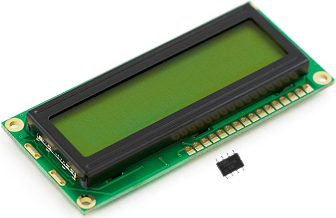
A shift register 74HC595 was chosen for operation, due to the presence of a latch that allows to organize the output of data on demand. The display is compatible with HD44780 (for operation in 4-bit mode), and the ATtiny13A microcontroller.
This choice was not due to the absence of more powerful microcontrollers, but by the narrowing of the scope of the task, the number of outputs, memory and RAM, and simply for sporting interest.
Objective: to create a code that can be executed on a given equipment, not to the detriment of performance, usability and completeness of functionality.
Start the display.
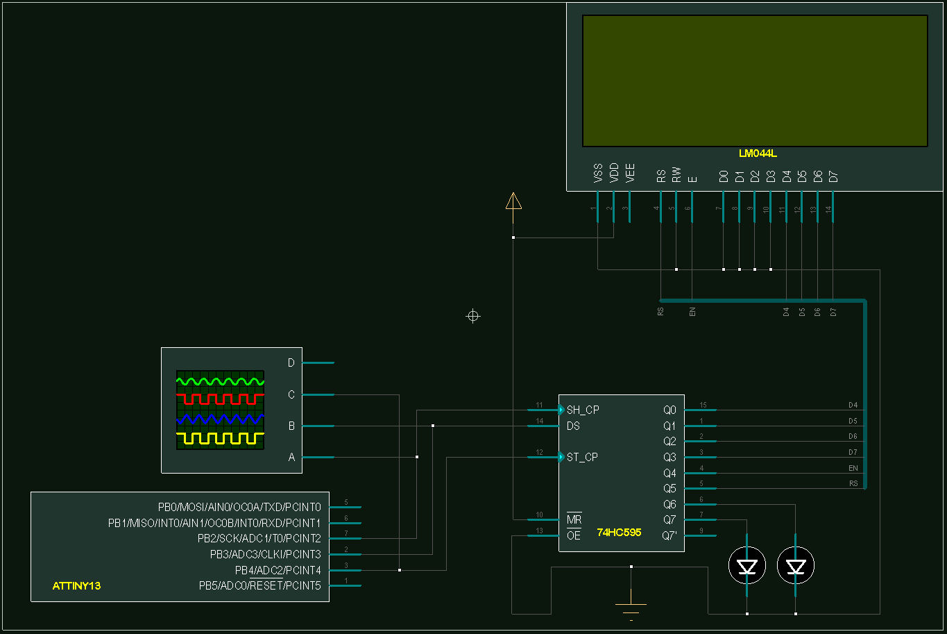
The first thing that needed to be organized was the output of data through a shift register at an acceptable speed, which was done using the Tinki three legs.
The image of the described connection is as follows:
 Then a function was written to output data in a format acceptable to the LCD. This function is a kind of core or library driver on which all subsequent output is based. As well as an additional (auxiliary function), which organizes data fragmentation into nibbles (nibbles), and sends them to the LCD through a shift register, calling the main data transfer function.
The implementation of the functional part.
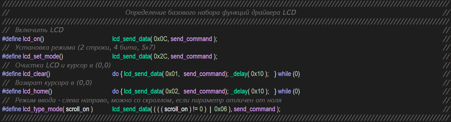
As soon as this part of the work was completed and tested, I proceeded to organizing the lower level LCD control functions, which are described in the LH for the device, as necessary for the initial initialization of the LCD, as well as directly the initial initialization function itself, without which the LCD will not even turn on .
And since only one output function (the driver described above) is intended for sending data to the LCD, all other functions are easily organized through its call, with the transfer of the corresponding parameters. So, to save the memory of programs, all other functions can be defined through the directive #define.
At this moment, I found an initialization method that no one uses, but it is described in detail in the HITACHI LH (if my memory serves me). It lies in the fact that to switch the data line width in the LCD, it is necessary that the first TWO teams were 4-bit, and that's it!
When I studied LCD control issues while reading various websites, a standard initialization mode known to many was described there.
The result was the writing of two initialization functions to avoid problems when working with LCD from other manufacturers. The mode is determined by the directive at the beginning of the program.
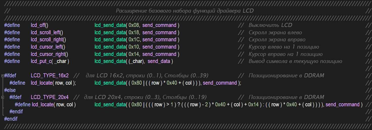
After that, a set of functions was defined, expanding the basic set of LCD control functions, which also included the cursor positioning function, for two types of LCD devices - 1602 and 2004 (the type switching is organized by a directive at the beginning of the program), and the function for displaying characters:
Next, an auxiliary set of top-level functions was written to organize the display of data of standard types, such as: byte, word, HEX byte, string, etc.
For the output of numerical data, the functions of fast division into 10 and 100, as well as auxiliary macros, which “rake” the remainder of the corresponding division (trick), were written. Thus, instead of 5 divisions for the output of uint16, fewer divisions are required - 4 instead of 8, and for uint8 - 2 instead of 4-eh. Also, the functions of defining new characters, the Russian text conversion code for strings in RAM, the output of strings from program memory with text recoding are written.
Here is this set:

Where two auxiliary functions are included, which organize the output of a byte bitmap, and the masked output of a byte bitmap, to be able to control the state of certain bits specified by the mask. The video below shows this.
However, to display in real hardware, character codes will have to be changed to others, or alternative characters created, and their codes used. The comments to these functions indicate where to change this.
And finally, this whole “vinaigrette” has been expanded by the topmost set of functions,
organizing data output at a specific screen position. It was done the same way through the directive #define:

The presented excerpts of the code show how much the code is described by comments, so that there are no problems with its use. The result of the optimization was the ability to display a fairly rich output, with a very modest code size, but the speed of its operation did not impress me. And also, after analyzing the use of the stack and nesting levels, it was decided to rewrite the function of the output kernel to get rid of the auxiliary function (which took 2 parameters), which greatly unloaded the stack, reduced the code by 100 bytes, but did not greatly accelerate the output.
Modernization of the hardware.
And at that moment I came across an example of 10 years old Germans, who organized the output of data in a shift register, using an RC chain. Firstly, the implementation of this method allowed us to release one leg of the microcontroller, and secondly, it pushed me to new reflections.
So, after analyzing the data transfer protocol, I realized that the output of the “E” -LCD signal and the output of the shift register latch are the same!
And this means that you can free up one line of the shift register, and speed up the data output in TWO TIMES!
Subsequently, the RS-LCD output was also transferred to the data line, which made it possible to release another shift register line, and the data transfer protocol was rewritten taking this fact into account.
The result was a single kernel function that accepts data and a flag (the output of a command or function), which itself parses the nibbles and outputs them to the data line with the necessary delays, and does not exceed 100 bytes.
The LCD data bus (4 bits) occupies half the output of one shift register, the other half can be used to indicate, which I showed in a demo example.
Later, I came across a simplified description of using RC chains for a shift register on DIHALT'a site - easyelectronics.com, and wanted to place all the material there, but could not log in with my account, although I entered the credentials correctly. Or maybe confused sites - the main and community site. In general, I did not get very upset, DI anyway hello :)
And for those who feel a lack of knowledge in the field I am describing, I suggest visiting this resource to eliminate this shortcoming. DIHALT and members of the community described in great detail all the devices in question.
In addition, information about the connection and use.
I did not bring the code to a separate library, the generated code is easily converted for any development related to the output of data on the LCD. The disadvantages include the impossibility of reconfiguring the LCD data bus sitting on the shift register, it always occupies lines 0 to 3 (although it is possible to “flip” the shift register outputs by replacing the left shift command “lsl” in the output function with the right shift command “ rsl ", which will" change "the assignment of the outputs of the shift register, and the data bus will be on pins 7 to 4). But the microcontroller pins can be configured any, and for any MK, but with the proviso: the lines must be on the same port (again, provided the port number is reassigned as an output function, in the considered case port = 0x16).
The code contains a couple of clever tricks that can be useful not only for the specified area (for example, dividing by 10 and 100 with the rest).
The code does not use interrupts and other peripherals, except for hardware PWM, which was initially initialized for diagnostic purposes, and subsequently left for a demo (PB0 line - PWM, PB1 - inverse PWM, changes from the state of the LEDs). With this, you can, for example, control the brightness of the display backlight - programmatically.
Thus, it is the smallest library of data output on the LCD (and perhaps the fastest, and the most documented in the code :)
I would like to add that testing was not done in hardware, but based on the measured deviations of the parameters of the RC chain, I think there should be no problems.
If there are brave souls who will verify this matter in the gland, I will be extremely grateful.
I also note that the performance has been tested for the frequencies of the MK 9.6 MHz and 4.8 MHz (for the latter, it is necessary to change the resistance of the RC-chain to 9k).
The capacitor in the gland should be 100 pF (10 pF - tolerance on the capacity of the legs of the port of MK).
Separately created section INIT3, to pre-initialize the parameters of the IC and start the display after turning on the device, it looks like this:

Examples of application.
To demonstrate the performance, capabilities and processing speed, a demo mode was written, which uses far from all functions, nevertheless, a set of them sufficient for understanding.
Video emulation in the Proteus program demonstrates this:
I apologize for the voice acting, I forgot to turn off the sound on the second monitor, I hope it does not distract from viewing.
Some technical information.
From this data:
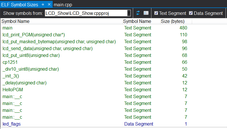
it is clear that the demo uses 480 bytes in the main function. The rest of the code is the library functions used, cp1251 is the character conversion table (33 * 2), HelloPGM is the string constant “Hello, Habr”, and the last 4 code fragments are 7 bytes each (the string constants for outputting the modes are “Red”, “Green” , "Blue", "Yellow" aligned with spaces), are stored in flash-memory.
1 byte of RAM - takes the variable states of the LEDs.
In the video, the characters used are embedded in the Proteus library , which has been completely redrawn. Therefore, the image in the gland will be different. :)
But performance will not suffer from this!
Time parameters of the pulse signals and data packet for those who wish:
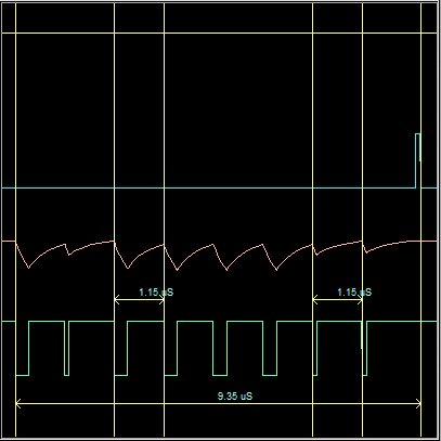 |  |
From which it can be seen that the duration of the signal “0” and the signal “1” (the first figure) coincide completely in time, since the data output function has been optimized taking into account the complete elimination of jitter.
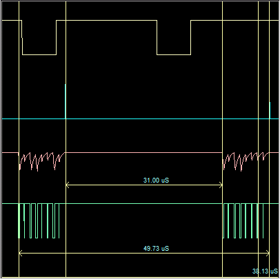
The second picture reflects the transfer of one packet (byte) to the LCD, since the data bus is 4-bit, this transfer is carried out in two stages, between which the delay follows in order for the LCD to “digest” the first part of the data.
Who is interested in the output function, it is here:

(Here also used a trick with a conclusion, characteristic only for Atmel MCs).
Conclusion
If someone decides to embody my creation in hardware, and will experience problems with the launch, I recommend playing with a delay (indicated by the #define directive in the section describing global data). Help will be needed, please contact us with questions in the comments to the article, I will be happy to help. I almost forgot to add: When using interrupts, you will have to provide barriers in the function of outputting data to the line yourself (at the end of the function there are examples of saving and restoring the SREG (status register) under the comment). Otherwise, there will be the problem of calling an interrupt during the data transfer function, which will lead to a malfunction (instructions: cli and sei - not enough!).
As always - postscript:
I decided to check how much we are adapting the code for new developments related to data output, and the first thing that came to mind was the implementation of a volt-meter on ATtiny13A.
The development of the presented implementation took no more than 30 minutes, most of which took the design of the scheme.
Two-channel ampere-, volt-meter:
Channel 1: 0-60V, 0-40A
Channel 2: 0-15V, 0-10A
Code size: 760 bytes
Peripherals used: ADC0, ADC1, ADC2, ADC3
RESET - disabled, uses the entire PORTB.
Perhaps the article made inaccuracies, also, inaccuracies are possible in the profiling results indicated in the code in the margin, the code has been rewritten repeatedly. Regarding the performance of the code, I can assure you that all functions have been tested many times.
The source code of the demo for Atmel Studio 7.0, and the project for Proteus 8.3 sp2 - is attached , no further changes will be made.
As always, I wish you all success in your work ... and in other endeavors!
Soon spring!
Use in commercial projects, resale of the source code, use for the purpose of profit and any mercenary purposes is prohibited. Source texts are distributed free of charge as they are, in case of use on other sites or other sources, the indication of the author and notification of placement is a must!
Source: https://habr.com/ru/post/274895/
All Articles