Create a hardware keyboard logger
You probably have more than once had a situation when the program loggers Claudia could not solve the tasks. For example, it is impossible to catch a password from a BIOS using a software keylogger loaded by the system. Personally, I ran into a similar problem when I needed to know the admin password in the local network of one company. Then I thought that it would be very cool to make an “iron” logger that would connect between the keyboard and the computer and catch all keystrokes starting from turning on the computer. The proposed article outlines the principles of the PS / 2 interface, and the interception of data transmitted through it.
A couple of keyboard hardware loggers
')
In order to design such a device, you first need to figure out how the keyboard works. There are two main types of keyboards: AT (old standard) and PS / 2. They differ only in connectors: AT has DIN, and PS / 2 - miniDIN. The first is a large round connector with five pins, the second is small, like a mouse, with six pins. According to the exchange protocol, they are fully compatible. Surely, you saw adapters from wide old connectors to new small ones. This standard appeared in 1984 together with the first IBM PC personal computer and is used to this day, almost without any changes.
The keyboard is a matrix of buttons (about eight lines for 16 columns), which are removed by the keyboard controller and, when pressed, are transmitted as scan codes to the computer (not to be confused with ASCII codes). Between the keyboard and a computer installed two-way exchange. The keyboard controller transmits the scan codes of the keys pressed: the scan code of the key release along with the scan code of the key itself. The keyboard controller, located on the computer's motherboard, determines the functions of the keyboard (if, for example, a key was pressed) and sends them to the system. He can control the controller built into the keyboard, for example, blink LEDs on the keyboard, set the auto-repeat speed of the keys, etc. Simply put, there is a chip in the keyboard that stupidly throws all the keys pressed into the wire, then another chip decodes these scan codes on the motherboard and controls the keyboard. Therefore, if we connect to the keyboard wire, listen to what's going on there, and save it to some memory, we can completely recover what was typed on the keyboard at that moment.
The general principles are clear, now let's find out which protocol is used for data exchange between the keyboard and the motherboard. It should be immediately noted that the keyboard is correcting the ball and is a higher priority device on its interface than the motherboard. From the connector on the motherboard to the keyboard goes four wires: a common wire (GND), +5 volts, data (Data) and a clock signal (Clock).

Pinout keyboard connectors (old and new)
The keyboard operation protocol is sequential, that is, a byte is transmitted all over one wire, synchronized with a clock signal. In quiescent mode, the Clock signal is at a high level (logical unit). When we press a key, the keyboard starts data transfer.
Serial keyboard inferface.
The clock signal assumes the state of logical zero (goes from high to low), and zero bits are set on the data bus. This bit is called Start bit, it gives the controller on the mother to understand that we are starting to transfer data. Further, the clock signal again takes on the value of a logical one, and the zero bit is transmitted to a logical zero by the new decay. Thus all 8 bits of the code are transmitted, starting with the zero and ending with the seventh bit. The transmission ends with one parity bit (Parity Bit), confirming the validity of the received data, and a stop bit (Stop bit), indicating that the transmission is over and the next byte can be transmitted. It turns out that one parcel takes 11 bits, including auxiliary bits. This is more clearly shown in the pictures and in the video below.

Oscillogram of transmitted data from the keyboard. Above signal Clock, below Data
From this it follows that we first need to listen to the Clock signal and read from the decline of its fronts what is happening on the data bus.
So, with the protocol of the keyboard, everything seems to be clear. Now let's see what kind of data is plying from the keyboard to the computer and back. This data can be divided into three groups.
1. Control commands sent by the computer to the keyboard.
For example: FFh - - reset the keyboard. These commands can light up the LEDs on the keyboard, control its operation, etc. An interesting group of commands allows you to very flexibly reconfigure the keyboard and even accelerate or slow it down (hello to overclockers :)). There are eight teams in total, they have the reserved codes EDh, EEh, F0h, F3h, F4h, F5h, FEh and FFh. Each code is a separate command, the purpose of which you can find out in the documentation.
2. Commands sent by the keyboard to the computer.
This group of commands shows us the status of the keyboard or some processing problems. For example: 00h - an error or keyboard buffer overflow. These teams are only seven pieces, they have codes FAh, AAh, EEh, FEh, F0h 00h and FF. We are interested in two teams: AAh and F0h. The AAh command indicates that the power-on self-test was successful. Now we can be 100% sure that the keyboard is on. From the moment this command is passed through the wires, we can safely launch our logger and monitor the keys typed on the keyboard. By the way, when booting the BIOS, it swears at the lack of a keyboard, it informs us that it did not receive the very command AAh - the self-testing of the keyboard did not go successfully. F0h also shows that the pressed key was pressed.
3. And finally, the most important group of data sent by the keyboard to the computer is the scan codes of the keys pressed. As I said before, the scan codes of most keys take up 1 byte. For example, the F1 key has a scan code of 05h. But there are advanced keys, scan code which takes 2 or more bytes. For example: the right Alt scan code will look like E0 11h, and the Pause key will have E1 14 77 E1 F0 14 F0 77h, as many as 8 bytes! Hence the interesting conclusion that the number and functionality of the keys can be expanded indefinitely and you can make your own keyboard with any possible number of keys by assigning any functions to them: from controlling Winamp to launching nuclear warheads. For example, I will show which commands will go to the computer when typing my dick nlinyj on the keyboard:
23 F0 23 4B F0 4B 43 F0 43 31 F0 31 35 F0 35 3B F0 3Bh
Everything is logical here, the scan codes of the keys will be: d = 23h, l = 4Bh, i = 43h, n = 31h, y = 35h, j = 3Bh, and F0h is a command that shows which key was pressed at what point . That is, the code of the pressed key is sent first, then when it is released, the command that the key was pressed and the code of the pressed key are sent. You can hold several keys in any order and press them in a different order, the computer will accept it.


Key Scan Code Table
Transfer scancode keys to the computer.
What it looks like on an oscilloscope.
Usually, the development of a device begins with the iron part, and then a program is written to the hardware. But we did everything at the same time: we soldered iron and wrote software. However, the principles of building the hardware were laid at the idea stage.
First you need to outline the range of tasks that we set, making this logger. The task before us was the following: to create a device inserted into the break of the keyboard wire and tracking keystrokes. Further, this device, depending on the configuration of the program, should have been able to store keystrokes in non-volatile memory. Then it was necessary to realize the possibility of removing this log through a computer interface, such as USB. It was also important to take into account the various options for the development of this device: connecting a radio transmitter, storing large amounts of data, translating into ASCII code on the go, pairing with many computer interfaces. Looking ahead, I will say that our device implements all possible ways to extend its functionality.
We chose the AVR family of processors. They are ideally suited for the task: they are inexpensive, very easy to learn, they have abundant peripherals, there is an operational and, most importantly, non-volatile memory - EPROM. From the family we selected the most simple and cheap ATtiny2313. This pebble costs only $ 1.5-2 and has 2 KB of program memory on its board, 128 bytes of RAM and the same non-volatile memory. He also has important for us serial interfaces SPI and UART. By SPI, we can connect external memory (for example, a 4 GB MMC card) or by using a programmer, without directly disconnecting our device from the keyboard, to merge the contents of non-volatile memory. The UART is an asynchronous transceiver, an enhanced version of the RS-232 protocol (see my article on Habre ). It will serve us to connect the controller with the computer via matching circuits. But the main thing is that our processor can handle external interrupts. There is a controller foot that can respond to a signal change. For example, if we have a signal in a logical unit, then an interrupt will be processed. We need to configure the device so that the interrupt is triggered by the decay (that is, the transition from logical unit to zero) of the CLOCK signal in the keyboard. We will connect the Data to the INT1 pin. Interrupt it will not process. This is done so that without changing the code, it can be easily transferred under another processor - INT0 and INT1 are always on the same pin of port D on any processor of the AVR family: PD2 and PD3.
You can merge data from an EPROM in two ways. The first way is to merge non-recoded data using a programmer, and then transcode with your program. This method is good because you do not have to fool with all sorts of interfaces, etc. Just a few wires to the LPT port and that's it. The second option is to download already prepared text in ASCII-codes via RS-232 port. To do this, the processor has legs RX and TX, like a COM port.
But do not rush to immediately connect the processor directly to the computer - you just burn it. The fact is that the signal level of the COM port is different from that of the processor. Logical zero At the COM port is encoded as -15 volts, and the unit - as +15 volts. And the processor - from zero to +5 volts. There are coordination schemes, many of which you will find on the Internet and radio magazines. The easiest way is to use a cord for a mobile phone, which costs only 30 rubles on the market. It is on USB, but at the end of it there are cherished contacts RX and TX, which should be connected to the mobile phone. If you connect it to USB and install all the necessary drivers, then another COM port will appear on your system. Pinouts of such laces can be found on our disk. Do not forget only that the signal RX - means reception, and TX - transmission. According to this, the RX signal of the microcircuit should be hooked onto the TX leg of the processor and vice versa
Any microprocessor development must begin with time-tested solutions. To begin with, this development should be debugged on ready-made solutions, for example, with a display, with interface with a computer, etc. Therefore, we have taken a prototype board with an already built-in display and with a fully established procedure for working with it. This was necessary in order to make sure that we see and monitor the keyboard.
First of all, we applied power to the keyboard and looked at the oscilloscope to transfer data from it. This is an important point, since at this stage it is possible to identify some undocumented protocol capabilities that will later create a large rake. For example, different types of keyboards may have missing or incorrectly displayed parity bits. But in our case, everything was in order.

USB debug board
Next, we connected the keyboard to the processor and tried to just catch the interrupt without converting it into a scan code. At first there were some problems: it was not caught, then FFh appeared. It turned out that when zapayke we swapped the signals Clock and Data. After their rearrangement, everything fell into place. Keystrokes immediately displayed on the display. The first two digits are how many bytes were received since the power was applied. The second pair of numbers - the last received byte, the third and fourth - the penultimate and last byte, respectively.
This task, very simple at first glance, was solved for three days. At first, strange incomplete glitches appeared - as it turned out, the proprietary programmer simply corrupted the code. When we solved this problem, we started troubles with the compiler. In general, development is a slow and tedious task, but worth it!
Further, a long-written library of work with UART for interfacing with a computer was bolted on. A DATA cable from a mobile phone was used to connect the processor to the computer, and our entire circuit was powered from it. To do this, it was necessary to disassemble the cable itself, find the documentation for the pinout of the cables for mobile phones and properly unzip everything. When everything was done and the program code worked along with the hardware, we saw keystrokes in the terminal program.

Hardware source
The last step was to work with non-volatile memory integrated in the processor. At our disposal there were only 128 bytes of memory, and when you consider that each key takes at least 3 bytes (press, release code and press key code), then it should be enough for exactly the password from the OS, no more. ATmega8 has 512 bytes of EPROM, which is 4 times more than ATtiny2313, and, perhaps, you will have time to capture some moments from the correspondence. In this memory, the recording procedure was initially cyclical: we write to memory, we reach the end and we write again from the beginning. It turned out that the source text is overwritten. The final touch was the written part of the program, which determined the end of the memory and no longer continued recording.
Then we began to bring the debug option in the divine form. First, a board was made, in which errors were discovered after sealing, and it was rejected - it was necessary to do everything anew. Then we removed the extra debugging functions, sharpened the code and fixed errors. Finally, the code was moved to a steeper and more expensive ATmega8 processor to increase the EPROM. This was done partly due to the fact that at one time I was already doing a similar development, but did not bring it to mind, and the board remained. And in order not to disappear to the good, I was confused and transferred the code, since it was easy.
At the time of publication of the article, you can merge data through UART, but only in the form of scan codes, and then re-encode them (absolutely hacker approach - learn all keyboard scan codes and do the whole procedure in mind), or use our pascal program. I hope that all possible functions will be implemented in the final product. Now the data is merged by sending any character to the port to which the controller is connected. For this it is convenient to use a special terminal program, which lies on our disk.
The program code is very voluminous, so it did not fit into the article and you can see it in the appendix - everything is detailed there, there are comments. But I will explain the general approach.
The program code can be divided into characteristic functional blocks that perform specific tasks. The first block starts after the computer is turned on. It initiates interrupts (interrupt from UART and interrupt due to decay of CLOCK signal), asynchronous transceiver aka UART itself. Volumes of operative and non-volatile memory are cleared and initialized. The stack is determined. Well, in general, a full initialization and tincture of all equipment is carried out. The second main block is the keyboard interrupt handler. I will tell about it in more detail.
This is the keyboard interrupt handler. In the event of a falling front on the INT0 pin, to which the CLOCK signal is connected, this interruption is triggered by us. The first command increases the number of bits received. The second and third check the value of the counter, comparing it with the unit. Third: if the counter is equal to one, then this means that a start-bit has been received, and this is the beginning of the transfer.
Here we check the start bit. When the start bit arrives on the data bus, there must be a logical zero. If we do not have a zero on the pin where the Data signal comes, it means that there was a bounce of contacts and we are not interested in this data - then everything is reset and begins again.
Here we again look at the number of bits received, but here it is already determined whether we have reached the end. The value should lie in the range from 1 to 8. If it is greater, then it means that it is a stop bit or a parity bit. And we move to the unfinished parity check procedure. If you have a desire, you can add it, but, as practice has shown, there is no need for it. The probability of error is too small.
The obvious part of the program. First we clear the carry flag. Next, we look at the state of the data port coming from the keyboard. If we have a unit at the entrance, then we set the transfer flag with the sec command; if it is zero, then we omit the flag setting command. Then we push the received bit from the carry flag into the KbdData register.
In the remainder, we check the number of last received bits. In the procedure KbdStateAsk there should be a parity check. rcall SendEvent - a procedure call that puts the received data into an EPROM. After that we clear the received bits counter and exit the interrupt handling procedure.
In the next block, we have a procedure for writing to an EPROM — a non-volatile memory where the collected contents of the KbdData register is placed. It is recorded there from the beginning of the memory and until we exhaust its volume.

The contents of the EEPROM (bottom window) after removing the log.
The last block is the interrupt handling from the UART. If we have an interrupt, we merge in a different data type, depending on the received symbol. But so far only a binary form is available, and for this, the Latin letter b is used.
If you carefully review the code on the disk, then you may encounter several auxiliary procedures. These are remnants of previous programs that we needed to debug, but they do not interfere with the code at all. There is a LED blinking procedure and procedures for working with segmented LCD displays. By the way, this code is a multitasking real-time operating system for AVR microcontrollers, which Comrade Dihalt brought to mind.
For communication with a computer controller has a UART interface. It can be connected to the COM port of the computer through such a matching circuit.
Interface scheme on MAX232
This is the most common and already dying scheme. She dies together with COM ports. For example, in my laptop is no longer a COM port. And what to do? There are similar ICs for communication. For example, the most common FT232BM or its more advanced modification with less binding is FT232R. This chip, after successfully sealing and installing all the necessary drivers, is seen in the system as a COM port. By the way, this is an important point for those who have a laptop and ancient devices, but there is no good old port. By combining both schemes, you can get a full-fledged COM port, to which it is possible to connect a modem or even an old mouse.

Board with FT232BM
In my opinion, the most convenient and cheapest option is to use a cord from a mobile phone. It performs the same functions as the FT232 chip. There, too, need to put the drivers and a bit pomemorritsya with pinout connector. But the gain in price will be obvious - it is 10 times cheaper. We tried all three options and came to the conclusion that the lace for small crafts is the perfect solution.

Mobile Phone Lace
In this article, we examined in detail the process of developing and manufacturing a radio electronic device. Such approaches are used in the design of motherboards, mobile phones, microwaves, and all electronics in general. The most important thing in our development is that it has, where to grow. You, having picked the code and having understood it, you can add necessary procedures. And if you do not add, then find ready on the Internet. The main thing is to figure out how to dock them. For example, you can find a radio transceiver on the UART. Such devices are many, and they are inexpensive - about $ 50. By slightly altering the code, you will receive a transmitting logger, the log of which can be received on a laptop in the yard. You can hang an external flash drive on gig, so that once a month just walk and collect logs. In short, applications are darkness.

Ready logger
I can say that the device is still quite raw. It is necessary for him to add a client program that can decode keystrokes. It is also worth writing the interface of an external flash drive, since Internal EEPROM is very small for experiments, and its resource is so small that at the stage of writing this article I exhausted it. But the ground for experiments is immense.
ZY This article is an adapted version of my article in "Hacker" in September 2007, which was called: "We spy on Aunt Klava."
ZZY Of course, this device demonstrates the principle of the keyboard. And using it as espionage can entail criminal liability. The author is not responsible for the use of this information.
References and links.
1. Source and technical description collected in one archive http://narod.ru/disk/1027682001/%D0%A1%D0%BE%D1%80%D1%86% D1%8B%20%D0%B8%20 % D0% B4% D0% BE% D0% BA% D0% B8.rar.html
2. The real-time operating system used in the device (we look from the bottom to the top, initially it is in assembler, then Di rewrote in C) http://easyelectronics.ru/tag/rtos
3. Terminal programs http://easyelectronics.ru/terminalnye-programmy.html
A couple of keyboard hardware loggers
Principles
')
In order to design such a device, you first need to figure out how the keyboard works. There are two main types of keyboards: AT (old standard) and PS / 2. They differ only in connectors: AT has DIN, and PS / 2 - miniDIN. The first is a large round connector with five pins, the second is small, like a mouse, with six pins. According to the exchange protocol, they are fully compatible. Surely, you saw adapters from wide old connectors to new small ones. This standard appeared in 1984 together with the first IBM PC personal computer and is used to this day, almost without any changes.
The keyboard is a matrix of buttons (about eight lines for 16 columns), which are removed by the keyboard controller and, when pressed, are transmitted as scan codes to the computer (not to be confused with ASCII codes). Between the keyboard and a computer installed two-way exchange. The keyboard controller transmits the scan codes of the keys pressed: the scan code of the key release along with the scan code of the key itself. The keyboard controller, located on the computer's motherboard, determines the functions of the keyboard (if, for example, a key was pressed) and sends them to the system. He can control the controller built into the keyboard, for example, blink LEDs on the keyboard, set the auto-repeat speed of the keys, etc. Simply put, there is a chip in the keyboard that stupidly throws all the keys pressed into the wire, then another chip decodes these scan codes on the motherboard and controls the keyboard. Therefore, if we connect to the keyboard wire, listen to what's going on there, and save it to some memory, we can completely recover what was typed on the keyboard at that moment.
Keyboard Protocol
The general principles are clear, now let's find out which protocol is used for data exchange between the keyboard and the motherboard. It should be immediately noted that the keyboard is correcting the ball and is a higher priority device on its interface than the motherboard. From the connector on the motherboard to the keyboard goes four wires: a common wire (GND), +5 volts, data (Data) and a clock signal (Clock).
Pinout keyboard connectors (old and new)
The keyboard operation protocol is sequential, that is, a byte is transmitted all over one wire, synchronized with a clock signal. In quiescent mode, the Clock signal is at a high level (logical unit). When we press a key, the keyboard starts data transfer.
Serial keyboard inferface.
The clock signal assumes the state of logical zero (goes from high to low), and zero bits are set on the data bus. This bit is called Start bit, it gives the controller on the mother to understand that we are starting to transfer data. Further, the clock signal again takes on the value of a logical one, and the zero bit is transmitted to a logical zero by the new decay. Thus all 8 bits of the code are transmitted, starting with the zero and ending with the seventh bit. The transmission ends with one parity bit (Parity Bit), confirming the validity of the received data, and a stop bit (Stop bit), indicating that the transmission is over and the next byte can be transmitted. It turns out that one parcel takes 11 bits, including auxiliary bits. This is more clearly shown in the pictures and in the video below.
Oscillogram of transmitted data from the keyboard. Above signal Clock, below Data
From this it follows that we first need to listen to the Clock signal and read from the decline of its fronts what is happening on the data bus.
Keyboard data
So, with the protocol of the keyboard, everything seems to be clear. Now let's see what kind of data is plying from the keyboard to the computer and back. This data can be divided into three groups.
1. Control commands sent by the computer to the keyboard.
For example: FFh - - reset the keyboard. These commands can light up the LEDs on the keyboard, control its operation, etc. An interesting group of commands allows you to very flexibly reconfigure the keyboard and even accelerate or slow it down (hello to overclockers :)). There are eight teams in total, they have the reserved codes EDh, EEh, F0h, F3h, F4h, F5h, FEh and FFh. Each code is a separate command, the purpose of which you can find out in the documentation.
2. Commands sent by the keyboard to the computer.
This group of commands shows us the status of the keyboard or some processing problems. For example: 00h - an error or keyboard buffer overflow. These teams are only seven pieces, they have codes FAh, AAh, EEh, FEh, F0h 00h and FF. We are interested in two teams: AAh and F0h. The AAh command indicates that the power-on self-test was successful. Now we can be 100% sure that the keyboard is on. From the moment this command is passed through the wires, we can safely launch our logger and monitor the keys typed on the keyboard. By the way, when booting the BIOS, it swears at the lack of a keyboard, it informs us that it did not receive the very command AAh - the self-testing of the keyboard did not go successfully. F0h also shows that the pressed key was pressed.
3. And finally, the most important group of data sent by the keyboard to the computer is the scan codes of the keys pressed. As I said before, the scan codes of most keys take up 1 byte. For example, the F1 key has a scan code of 05h. But there are advanced keys, scan code which takes 2 or more bytes. For example: the right Alt scan code will look like E0 11h, and the Pause key will have E1 14 77 E1 F0 14 F0 77h, as many as 8 bytes! Hence the interesting conclusion that the number and functionality of the keys can be expanded indefinitely and you can make your own keyboard with any possible number of keys by assigning any functions to them: from controlling Winamp to launching nuclear warheads. For example, I will show which commands will go to the computer when typing my dick nlinyj on the keyboard:
23 F0 23 4B F0 4B 43 F0 43 31 F0 31 35 F0 35 3B F0 3Bh
Everything is logical here, the scan codes of the keys will be: d = 23h, l = 4Bh, i = 43h, n = 31h, y = 35h, j = 3Bh, and F0h is a command that shows which key was pressed at what point . That is, the code of the pressed key is sent first, then when it is released, the command that the key was pressed and the code of the pressed key are sent. You can hold several keys in any order and press them in a different order, the computer will accept it.
Key Scan Code Table
Transfer scancode keys to the computer.
What it looks like on an oscilloscope.
Formulation of the problem
Usually, the development of a device begins with the iron part, and then a program is written to the hardware. But we did everything at the same time: we soldered iron and wrote software. However, the principles of building the hardware were laid at the idea stage.
First you need to outline the range of tasks that we set, making this logger. The task before us was the following: to create a device inserted into the break of the keyboard wire and tracking keystrokes. Further, this device, depending on the configuration of the program, should have been able to store keystrokes in non-volatile memory. Then it was necessary to realize the possibility of removing this log through a computer interface, such as USB. It was also important to take into account the various options for the development of this device: connecting a radio transmitter, storing large amounts of data, translating into ASCII code on the go, pairing with many computer interfaces. Looking ahead, I will say that our device implements all possible ways to extend its functionality.
We chose the AVR family of processors. They are ideally suited for the task: they are inexpensive, very easy to learn, they have abundant peripherals, there is an operational and, most importantly, non-volatile memory - EPROM. From the family we selected the most simple and cheap ATtiny2313. This pebble costs only $ 1.5-2 and has 2 KB of program memory on its board, 128 bytes of RAM and the same non-volatile memory. He also has important for us serial interfaces SPI and UART. By SPI, we can connect external memory (for example, a 4 GB MMC card) or by using a programmer, without directly disconnecting our device from the keyboard, to merge the contents of non-volatile memory. The UART is an asynchronous transceiver, an enhanced version of the RS-232 protocol (see my article on Habre ). It will serve us to connect the controller with the computer via matching circuits. But the main thing is that our processor can handle external interrupts. There is a controller foot that can respond to a signal change. For example, if we have a signal in a logical unit, then an interrupt will be processed. We need to configure the device so that the interrupt is triggered by the decay (that is, the transition from logical unit to zero) of the CLOCK signal in the keyboard. We will connect the Data to the INT1 pin. Interrupt it will not process. This is done so that without changing the code, it can be easily transferred under another processor - INT0 and INT1 are always on the same pin of port D on any processor of the AVR family: PD2 and PD3.
You can merge data from an EPROM in two ways. The first way is to merge non-recoded data using a programmer, and then transcode with your program. This method is good because you do not have to fool with all sorts of interfaces, etc. Just a few wires to the LPT port and that's it. The second option is to download already prepared text in ASCII-codes via RS-232 port. To do this, the processor has legs RX and TX, like a COM port.
But do not rush to immediately connect the processor directly to the computer - you just burn it. The fact is that the signal level of the COM port is different from that of the processor. Logical zero At the COM port is encoded as -15 volts, and the unit - as +15 volts. And the processor - from zero to +5 volts. There are coordination schemes, many of which you will find on the Internet and radio magazines. The easiest way is to use a cord for a mobile phone, which costs only 30 rubles on the market. It is on USB, but at the end of it there are cherished contacts RX and TX, which should be connected to the mobile phone. If you connect it to USB and install all the necessary drivers, then another COM port will appear on your system. Pinouts of such laces can be found on our disk. Do not forget only that the signal RX - means reception, and TX - transmission. According to this, the RX signal of the microcircuit should be hooked onto the TX leg of the processor and vice versa
Development process
Any microprocessor development must begin with time-tested solutions. To begin with, this development should be debugged on ready-made solutions, for example, with a display, with interface with a computer, etc. Therefore, we have taken a prototype board with an already built-in display and with a fully established procedure for working with it. This was necessary in order to make sure that we see and monitor the keyboard.
First of all, we applied power to the keyboard and looked at the oscilloscope to transfer data from it. This is an important point, since at this stage it is possible to identify some undocumented protocol capabilities that will later create a large rake. For example, different types of keyboards may have missing or incorrectly displayed parity bits. But in our case, everything was in order.
USB debug board
Next, we connected the keyboard to the processor and tried to just catch the interrupt without converting it into a scan code. At first there were some problems: it was not caught, then FFh appeared. It turned out that when zapayke we swapped the signals Clock and Data. After their rearrangement, everything fell into place. Keystrokes immediately displayed on the display. The first two digits are how many bytes were received since the power was applied. The second pair of numbers - the last received byte, the third and fourth - the penultimate and last byte, respectively.
This task, very simple at first glance, was solved for three days. At first, strange incomplete glitches appeared - as it turned out, the proprietary programmer simply corrupted the code. When we solved this problem, we started troubles with the compiler. In general, development is a slow and tedious task, but worth it!
Further, a long-written library of work with UART for interfacing with a computer was bolted on. A DATA cable from a mobile phone was used to connect the processor to the computer, and our entire circuit was powered from it. To do this, it was necessary to disassemble the cable itself, find the documentation for the pinout of the cables for mobile phones and properly unzip everything. When everything was done and the program code worked along with the hardware, we saw keystrokes in the terminal program.
Hardware source
The last step was to work with non-volatile memory integrated in the processor. At our disposal there were only 128 bytes of memory, and when you consider that each key takes at least 3 bytes (press, release code and press key code), then it should be enough for exactly the password from the OS, no more. ATmega8 has 512 bytes of EPROM, which is 4 times more than ATtiny2313, and, perhaps, you will have time to capture some moments from the correspondence. In this memory, the recording procedure was initially cyclical: we write to memory, we reach the end and we write again from the beginning. It turned out that the source text is overwritten. The final touch was the written part of the program, which determined the end of the memory and no longer continued recording.
Then we began to bring the debug option in the divine form. First, a board was made, in which errors were discovered after sealing, and it was rejected - it was necessary to do everything anew. Then we removed the extra debugging functions, sharpened the code and fixed errors. Finally, the code was moved to a steeper and more expensive ATmega8 processor to increase the EPROM. This was done partly due to the fact that at one time I was already doing a similar development, but did not bring it to mind, and the board remained. And in order not to disappear to the good, I was confused and transferred the code, since it was easy.
At the time of publication of the article, you can merge data through UART, but only in the form of scan codes, and then re-encode them (absolutely hacker approach - learn all keyboard scan codes and do the whole procedure in mind), or use our pascal program. I hope that all possible functions will be implemented in the final product. Now the data is merged by sending any character to the port to which the controller is connected. For this it is convenient to use a special terminal program, which lies on our disk.
Software implementation
The program code is very voluminous, so it did not fit into the article and you can see it in the appendix - everything is detailed there, there are comments. But I will explain the general approach.
The program code can be divided into characteristic functional blocks that perform specific tasks. The first block starts after the computer is turned on. It initiates interrupts (interrupt from UART and interrupt due to decay of CLOCK signal), asynchronous transceiver aka UART itself. Volumes of operative and non-volatile memory are cleared and initialized. The stack is determined. Well, in general, a full initialization and tincture of all equipment is carried out. The second main block is the keyboard interrupt handler. I will tell about it in more detail.
Int0Handler:
….
inc KbdRxState
mov Tmp1, KbdRxState
cpi Tmp1,1
brne KbdState1_8
This is the keyboard interrupt handler. In the event of a falling front on the INT0 pin, to which the CLOCK signal is connected, this interruption is triggered by us. The first command increases the number of bits received. The second and third check the value of the counter, comparing it with the unit. Third: if the counter is equal to one, then this means that a start-bit has been received, and this is the beginning of the transfer.
sbis KbdPort, KbdDat
rjmp Int0LEx
clr KbdRxState
rjmp Int0LEx
Here we check the start bit. When the start bit arrives on the data bus, there must be a logical zero. If we do not have a zero on the pin where the Data signal comes, it means that there was a bounce of contacts and we are not interested in this data - then everything is reset and begins again.
KbdState1_8:
cpi Tmp1, 10
brge KbdStatePar
Here we again look at the number of bits received, but here it is already determined whether we have reached the end. The value should lie in the range from 1 to 8. If it is greater, then it means that it is a stop bit or a parity bit. And we move to the unfinished parity check procedure. If you have a desire, you can add it, but, as practice has shown, there is no need for it. The probability of error is too small.
clc
sbic KbdPort, KbdDat
sec
ror KbdData
rjmp Int0LEx
The obvious part of the program. First we clear the carry flag. Next, we look at the state of the data port coming from the keyboard. If we have a unit at the entrance, then we set the transfer flag with the sec command; if it is zero, then we omit the flag setting command. Then we push the received bit from the carry flag into the KbdData register.
KbdStatePar:
cpi Tmp1, 10
brne KbdStateAsk
rjmp Int0LEx

KbdStateAsk:
….
KbdEndState:
…..
rcall SendEvent
clr KbdRxState
rjmp Int0LEx

Int0LEx:
….
reti
In the remainder, we check the number of last received bits. In the procedure KbdStateAsk there should be a parity check. rcall SendEvent - a procedure call that puts the received data into an EPROM. After that we clear the received bits counter and exit the interrupt handling procedure.
In the next block, we have a procedure for writing to an EPROM — a non-volatile memory where the collected contents of the KbdData register is placed. It is recorded there from the beginning of the memory and until we exhaust its volume.
The contents of the EEPROM (bottom window) after removing the log.
The last block is the interrupt handling from the UART. If we have an interrupt, we merge in a different data type, depending on the received symbol. But so far only a binary form is available, and for this, the Latin letter b is used.
If you carefully review the code on the disk, then you may encounter several auxiliary procedures. These are remnants of previous programs that we needed to debug, but they do not interfere with the code at all. There is a LED blinking procedure and procedures for working with segmented LCD displays. By the way, this code is a multitasking real-time operating system for AVR microcontrollers, which Comrade Dihalt brought to mind.
Computer mating
For communication with a computer controller has a UART interface. It can be connected to the COM port of the computer through such a matching circuit.
Interface scheme on MAX232
This is the most common and already dying scheme. She dies together with COM ports. For example, in my laptop is no longer a COM port. And what to do? There are similar ICs for communication. For example, the most common FT232BM or its more advanced modification with less binding is FT232R. This chip, after successfully sealing and installing all the necessary drivers, is seen in the system as a COM port. By the way, this is an important point for those who have a laptop and ancient devices, but there is no good old port. By combining both schemes, you can get a full-fledged COM port, to which it is possible to connect a modem or even an old mouse.
Board with FT232BM
In my opinion, the most convenient and cheapest option is to use a cord from a mobile phone. It performs the same functions as the FT232 chip. There, too, need to put the drivers and a bit pomemorritsya with pinout connector. But the gain in price will be obvious - it is 10 times cheaper. We tried all three options and came to the conclusion that the lace for small crafts is the perfect solution.
Mobile Phone Lace
Total
In this article, we examined in detail the process of developing and manufacturing a radio electronic device. Such approaches are used in the design of motherboards, mobile phones, microwaves, and all electronics in general. The most important thing in our development is that it has, where to grow. You, having picked the code and having understood it, you can add necessary procedures. And if you do not add, then find ready on the Internet. The main thing is to figure out how to dock them. For example, you can find a radio transceiver on the UART. Such devices are many, and they are inexpensive - about $ 50. By slightly altering the code, you will receive a transmitting logger, the log of which can be received on a laptop in the yard. You can hang an external flash drive on gig, so that once a month just walk and collect logs. In short, applications are darkness.
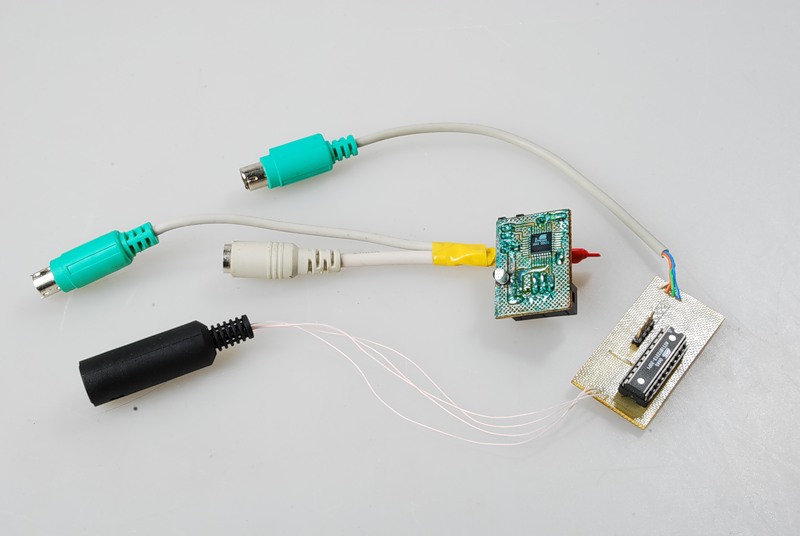
Ready logger
I can say that the device is still quite raw. It is necessary for him to add a client program that can decode keystrokes. It is also worth writing the interface of an external flash drive, since Internal EEPROM is very small for experiments, and its resource is so small that at the stage of writing this article I exhausted it. But the ground for experiments is immense.
ZY This article is an adapted version of my article in "Hacker" in September 2007, which was called: "We spy on Aunt Klava."
ZZY Of course, this device demonstrates the principle of the keyboard. And using it as espionage can entail criminal liability. The author is not responsible for the use of this information.
References and links.
1. Source and technical description collected in one archive http://narod.ru/disk/1027682001/%D0%A1%D0%BE%D1%80%D1%86% D1%8B%20%D0%B8%20 % D0% B4% D0% BE% D0% BA% D0% B8.rar.html
2. The real-time operating system used in the device (we look from the bottom to the top, initially it is in assembler, then Di rewrote in C) http://easyelectronics.ru/tag/rtos
3. Terminal programs http://easyelectronics.ru/terminalnye-programmy.html
Source: https://habr.com/ru/post/274835/
All Articles