Critical errors in the design of process control systems and PLC programming
In industry, automated process control systems (APCS) are being implemented on industrial programmable logic controllers (PLCs) at modernization sites. Newly supplied equipment, already by default contains an ACS on the PLC. But the quality of the design of the automated process control system and programming of the PLC sometimes does not correspond to the logic and requirements for reliable protection of the controlled object. In this article I will talk about a typical error in the design and programming of conventional industrial equipment.
Consider a typical object containing an ACS on a PLC in industry. In the mining industry, at the processing plants (PF), at the grinding stage of minerals (ore), various types of mills are used. They are ball, rod, vertical fine grinding, etc. The main function of these mills is the grinding of ore to the fraction needed later for the chemical extraction of minerals. Such equipment has its weak points during operation. Pobedit main bearings, gears, etc. They require constant monitoring of temperature, the presence of lubricant, etc. In case of overheating or dry running, the ACS should shut down the unit until the state of the nodes has reached a critical point. Software implementations of these protections and interlocks are typical and standard for this kind of equipment.
Let's consider two main errors in the design and programming of ACS for equipment of this type. The first mistake is incorrect design of the relay part of the control of the main drive or critical mechanism. The second error is the lack of a program in handling fatal PLC errors.
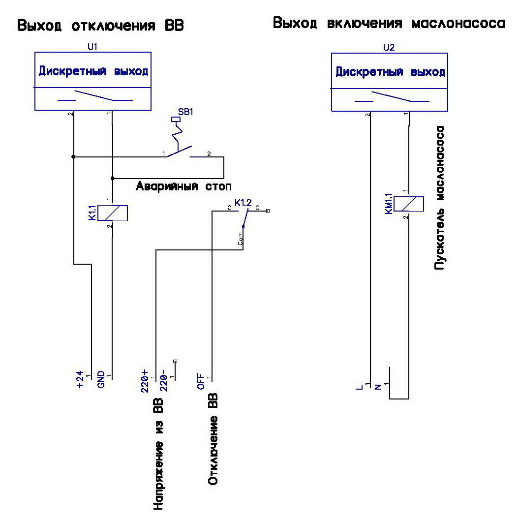
Consider the case with the relay part. The figure shows an example of such an error. The diagram shows only a part of the shutdown control of the main drive of the equipment.
')
At first glance, the usual relay circuit. But if you look at it, you can determine that sooner or later there will come a time when the relay circuit will not be able to turn off the main drive in the event of an emergency. Let's look at the scheme. The main drive is switched off by the PLC with a discrete output. In this circuit, it is a relay, but it can be transistor, the essence will not change. So, if for some reason the K1 relay coil burns during equipment operation, then in the event of an accident, the controller will give a signal to turn off the main drive, but the signal will not go further than the burned coil. But after all, according to the technology, when the main drive is disconnected, the auxiliary equipment is also required to be turned off, in this case it is an oil pump. So water in an accident, the oil pump will be safely disconnected, and the main drive will remain thresh on the "dry". Fortunately, the system will also turn on the alert, so that the nasty screaming bell and the blinking red lamp will attract the attention of the attendants and the “catastrophe” will not happen. After that, local electricians or Kipovtsy, find the cause of this disgrace, change the relay and everything will fall into place, perhaps someone will think about how to avoid it in the future, but hardly.
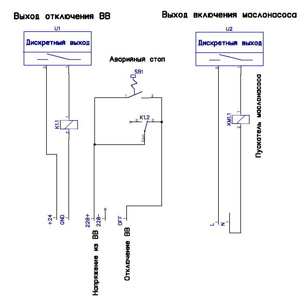
So in this circuit, relay K1 is a weak link. What can be done so that this does not happen. Elementary. The shutdown signal of the BB is put on the normally-closed contact of the relay K1, and the relay itself is attracted during the start-up of the main drive and is in working condition to keep it pulled. By the way, the emergency stop button is also not worth it. Either the contacts of the button must directly disconnect the actuator, or, if there are several such mechanisms, break the relay circuit, the contacts of which already disconnect the actuators. By the way, this inclusion of intermediate control relays for critical actuators also gives rise to erroneous testing with PLC programming errors.
When programming a PLC, some programmers make mistakes that lead to emergencies in production.
Recently I had to face this situation. The circuit for switching off the main drive was the same as above. A programming error caused the main drive to work for “dry” four hours, which caused the gearbox to overheat. As a result, the gearbox is completely out of order, and this is an expensive element in this equipment. What went wrong?
When identifying the cause of the accident, which led to high material costs, it was found that the PLC switched to STOP mode due to the watchdog timer. Accordingly, the relay circuit disconnected all auxiliary equipment except the main drive. The watchdog timer was triggered by the presence of a dead-end branch in the algorithm that did not cause a loop in the main function. And as you know, almost all firms producing PLC, the transition of the PLC to the "STOP" mode, is accompanied by the installation of discrete outputs in a safe state. In this case, the state is disabled. In this ACS, the programmer made two errors:
The first error we will write off on the complexity of the program, in which it is difficult to find this type of error.
The second error can be attributed only to the lack of competence of the programmer.
As is known, many PLCs have software modules for testing various fatal PLC errors. Consider these modules on the example of the PLC from the company Siemens.
Here is a small example of such an error.

Here, the programmer performs linearization of the analog input based on the library function FC105. In the main loop to enable bit M0.1, the analog signal is scaled. Everything would be fine, but if the FC105 is not loaded into the PLC, then when executing this line, the PLC will fall out into “STOP SF” if you do not specify a program error handler, the so-called OB121. If such a handler is flooded into the PLC, then with such errors the SF indication will appear, but the PLC will not go off to the STOP mode, and will continue to execute the user program.
The relay circuit must be designed in such a way that in any emergency situation, be it a technological accident or a PLC error, the switching off of the actuators is mandatory, regardless of the nature of the occurrence of the accident. Approaching programming of the PLC with full responsibility, because the equipment, which is designed to protect the process control system from critical operating conditions, leading to the destruction of mechanisms, is much more expensive than the control system itself.
In this scheme it was necessary to use the following inclusion of components of the relay scheme.
And in the software module OB121, perform some actions on archiving the failure that occurred in the PLC.
A video showing the behavior of PLC with software errors and their processing is presented below.
Schematic solution and software implementations are often deep errors that are not always detected at the start-up stage. In the course of operation, the specialists of the enterprise do not always carry out a complete test complex of the system reliability. In addition, the staff is often lacking qualifications. Let's hope that such emergencies will be negligible, and they will not lead to injuries at work.
PS
Leaving just empty software blocks for handling hardware or software errors is also not worth it. They need to perform any actions to detect such errors or to collect PLC failure statistics and possible causes.
Introduction
Consider a typical object containing an ACS on a PLC in industry. In the mining industry, at the processing plants (PF), at the grinding stage of minerals (ore), various types of mills are used. They are ball, rod, vertical fine grinding, etc. The main function of these mills is the grinding of ore to the fraction needed later for the chemical extraction of minerals. Such equipment has its weak points during operation. Pobedit main bearings, gears, etc. They require constant monitoring of temperature, the presence of lubricant, etc. In case of overheating or dry running, the ACS should shut down the unit until the state of the nodes has reached a critical point. Software implementations of these protections and interlocks are typical and standard for this kind of equipment.
What are the mistakes?
Let's consider two main errors in the design and programming of ACS for equipment of this type. The first mistake is incorrect design of the relay part of the control of the main drive or critical mechanism. The second error is the lack of a program in handling fatal PLC errors.
Errors in schemes.
Consider the case with the relay part. The figure shows an example of such an error. The diagram shows only a part of the shutdown control of the main drive of the equipment.
')
At first glance, the usual relay circuit. But if you look at it, you can determine that sooner or later there will come a time when the relay circuit will not be able to turn off the main drive in the event of an emergency. Let's look at the scheme. The main drive is switched off by the PLC with a discrete output. In this circuit, it is a relay, but it can be transistor, the essence will not change. So, if for some reason the K1 relay coil burns during equipment operation, then in the event of an accident, the controller will give a signal to turn off the main drive, but the signal will not go further than the burned coil. But after all, according to the technology, when the main drive is disconnected, the auxiliary equipment is also required to be turned off, in this case it is an oil pump. So water in an accident, the oil pump will be safely disconnected, and the main drive will remain thresh on the "dry". Fortunately, the system will also turn on the alert, so that the nasty screaming bell and the blinking red lamp will attract the attention of the attendants and the “catastrophe” will not happen. After that, local electricians or Kipovtsy, find the cause of this disgrace, change the relay and everything will fall into place, perhaps someone will think about how to avoid it in the future, but hardly.
So in this circuit, relay K1 is a weak link. What can be done so that this does not happen. Elementary. The shutdown signal of the BB is put on the normally-closed contact of the relay K1, and the relay itself is attracted during the start-up of the main drive and is in working condition to keep it pulled. By the way, the emergency stop button is also not worth it. Either the contacts of the button must directly disconnect the actuator, or, if there are several such mechanisms, break the relay circuit, the contacts of which already disconnect the actuators. By the way, this inclusion of intermediate control relays for critical actuators also gives rise to erroneous testing with PLC programming errors.
PLC programming errors.
When programming a PLC, some programmers make mistakes that lead to emergencies in production.
Recently I had to face this situation. The circuit for switching off the main drive was the same as above. A programming error caused the main drive to work for “dry” four hours, which caused the gearbox to overheat. As a result, the gearbox is completely out of order, and this is an expensive element in this equipment. What went wrong?
When identifying the cause of the accident, which led to high material costs, it was found that the PLC switched to STOP mode due to the watchdog timer. Accordingly, the relay circuit disconnected all auxiliary equipment except the main drive. The watchdog timer was triggered by the presence of a dead-end branch in the algorithm that did not cause a loop in the main function. And as you know, almost all firms producing PLC, the transition of the PLC to the "STOP" mode, is accompanied by the installation of discrete outputs in a safe state. In this case, the state is disabled. In this ACS, the programmer made two errors:
- The branched algorithm had a dead-end branch, which led to the triggering of the watchdog timer.
- There was no exception handling in the program, thus the PLC switched to the “STOP” mode.
The first error we will write off on the complexity of the program, in which it is difficult to find this type of error.
The second error can be attributed only to the lack of competence of the programmer.
As is known, many PLCs have software modules for testing various fatal PLC errors. Consider these modules on the example of the PLC from the company Siemens.
Here is a small example of such an error.
Here, the programmer performs linearization of the analog input based on the library function FC105. In the main loop to enable bit M0.1, the analog signal is scaled. Everything would be fine, but if the FC105 is not loaded into the PLC, then when executing this line, the PLC will fall out into “STOP SF” if you do not specify a program error handler, the so-called OB121. If such a handler is flooded into the PLC, then with such errors the SF indication will appear, but the PLC will not go off to the STOP mode, and will continue to execute the user program.
Let's sum up
The relay circuit must be designed in such a way that in any emergency situation, be it a technological accident or a PLC error, the switching off of the actuators is mandatory, regardless of the nature of the occurrence of the accident. Approaching programming of the PLC with full responsibility, because the equipment, which is designed to protect the process control system from critical operating conditions, leading to the destruction of mechanisms, is much more expensive than the control system itself.
In this scheme it was necessary to use the following inclusion of components of the relay scheme.
And in the software module OB121, perform some actions on archiving the failure that occurred in the PLC.
A video showing the behavior of PLC with software errors and their processing is presented below.
Conclusion
Schematic solution and software implementations are often deep errors that are not always detected at the start-up stage. In the course of operation, the specialists of the enterprise do not always carry out a complete test complex of the system reliability. In addition, the staff is often lacking qualifications. Let's hope that such emergencies will be negligible, and they will not lead to injuries at work.
PS
Leaving just empty software blocks for handling hardware or software errors is also not worth it. They need to perform any actions to detect such errors or to collect PLC failure statistics and possible causes.
Source: https://habr.com/ru/post/274727/
All Articles