Create 2D portals using shaders
In this article I will talk about how to achieve this effect:
Essentially, the shader in question works as a post effect for the camera or the built-in blur and vignette filters in Unity. It takes an input image (more precisely, RenderTexture) and displays it with superimposed effects.
')
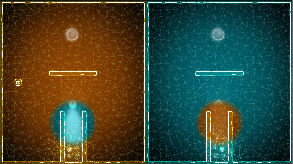
It all started with the game for the thirtieth gamedzhe Ludum Dare on the subject of Connected Worlds. The idea was as follows: two characters are on different sides of the screen, divided into two identical parts, and send signals to each other. Many players could not understand this mechanics, so I slightly changed it.
I made it so that, entering the portal, the signal would materialize in a parallel world - on another part of the screen. At the same time, I came up with several options for the portal, for example, when the characters got into it, they changed places. But all this was incomprehensible and even more confusing.
I puzzled over this problem for a long time, but it would be too difficult to tune each moving object. Then I decided that for this purpose you need to write a shader.
In fact, the shader, which will be discussed, works as a post-effect for the camera or the built-in Blur and Vignette filters in Unity. It takes an input image (more precisely, RenderTexture) and displays it with superimposed effects.
1. Configure the shader and post effects
Let's start with the least important post effect to test this configuration. First, create a camera, leaving most of the default settings:

The most important thing is to change the Clear Flags parameter (so that the screen is not updated when rendering), switch the camera to orthographic mode and set the depth value higher than for other cameras (to put the camera in the last drawing queue). Then we write a new script (PortalEffect.cs) with the following source code:
Now create a new shader PortalShader.shader with the following code:
Having created a shader, do not forget to set it in the PortalShader property of the PortalEffect script.
This is how the screen looks like before the effect is activated:

And so - after activation:

Gray appears because of the fixed4 line (.5, .5, .5, .1) and consists of 50% red, green, blue, and alpha with a value of 1.
2. Add UV Coordinates
Now add the UV coordinates to the shader. Their values can range from 0 to 1. It is easiest to imagine that this effect is superimposed on a quad, made to fit the screen, with a texture drawn by the previous cameras.
The following code snippet:
Thus, we double-flip the image vertically and horizontally, which corresponds to a 180-degree rotation:

Pay attention to the piece 1-i.uv. If we reduce it to i.uv, we get the so-called identical effect, which leaves the original image unchanged. The return tex2D string (_MainTex, float2 (1-i.uv.x, i.uv.y)) will simply flip the image horizontally (from left to right):

3. Transfer the screen area
We can slightly modify the shader by changing the values of the UV-coordinates to impose a specific area on another part of the screen.

In the screenshot you can see how the area on the left of the screen is copied from the right. The size of this section can be adjusted by changing the value of .25. We also add .5 so that the image moves to the opposite part of the screen - from 0–0.25 to 0.5–0.75 on the x axis.
4. Transferring the circular area
To transfer the circular area in the same way, add the distance function:

As you can see, instead of a circle, we have an oval. The problem is that the width and height of the screen are not identical (we calculate the distance in the range of 0–1). The height of the oval is 20% of the height of the screen, and the width is 20% of its width (based on a radius of .1 or 10%).
5. Transfer the circular area again
To solve this problem, we need to rewrite the distance function according to the width and height of the screen.

6. Swap areas
To complete a double replacement, we need to move a similar area to the right half of the screen:
This is what should happen:
7. Add blurry edges
Now the transition looks quite sharp, so we need to blur the edges a little. For this we use linear interpolation.
At first, everything is simple:
This code will blur the edges of the moved areas using 80% (this corresponds to 0.8) of the moved pixels:

Now let's make the transition even smoother using the distance function. Instead of doing a double substitution, we will focus on one area for now.
As you can see, it works, but requires additional configuration:

8. Blur faces with vignetting effect.
To solve this problem, I propose to go a workaround. Suppose we want to blur only the outer boundary with a thickness of 15. This means that for distances of 35 or less, the linear interpolation coefficient should be equal to one, and for a distance of 50 it should be zero. In the if branch, the distance is in the range from 0 to 50. So, to derive the final formula, we make up a small table:

The Saturate function is equal to Clamp (0,1), converting negative values to 0.
Using the final formula lerpFactor = 1 - saturate ((distance (scrPos, leftPos) -35) / 15), we get the following result:
Here is the full code for blurring the faces of two areas:
9. Configure Shader Parameters
Our shader is almost ready, but with hardcoded values it is of little use. We can extract them into the shader parameters and modify them with code.
After extraction, the final shader code looks like this:
Standard (asymmetric) values give us this result:

In our case, the shader parameters can be set in PortalEffect.cs:
10. Finishing Touches
Even with the vignetting effect, the transition does not look as we would like. This can be corrected by adding a border. In an older version of the code for this purpose, I used a particle system:


Drastically changing the style of the game, I used the Walls on fire shader to render regular round sprites around portals. Given that the rendering process takes place before the portals are swapped, this effect looks pretty cool:


11. End result
Here are some more gifs demonstrating the final result in action:

Essentially, the shader in question works as a post effect for the camera or the built-in blur and vignette filters in Unity. It takes an input image (more precisely, RenderTexture) and displays it with superimposed effects.
')
It all started with the game for the thirtieth gamedzhe Ludum Dare on the subject of Connected Worlds. The idea was as follows: two characters are on different sides of the screen, divided into two identical parts, and send signals to each other. Many players could not understand this mechanics, so I slightly changed it.
I made it so that, entering the portal, the signal would materialize in a parallel world - on another part of the screen. At the same time, I came up with several options for the portal, for example, when the characters got into it, they changed places. But all this was incomprehensible and even more confusing.
I puzzled over this problem for a long time, but it would be too difficult to tune each moving object. Then I decided that for this purpose you need to write a shader.
In fact, the shader, which will be discussed, works as a post-effect for the camera or the built-in Blur and Vignette filters in Unity. It takes an input image (more precisely, RenderTexture) and displays it with superimposed effects.
1. Configure the shader and post effects
Let's start with the least important post effect to test this configuration. First, create a camera, leaving most of the default settings:
The most important thing is to change the Clear Flags parameter (so that the screen is not updated when rendering), switch the camera to orthographic mode and set the depth value higher than for other cameras (to put the camera in the last drawing queue). Then we write a new script (PortalEffect.cs) with the following source code:
using UnityEngine; using UnityStandardAssets.ImageEffects; [ExecuteInEditMode] [RequireComponent(typeof (Camera))] public class PortalEffect : PostEffectsBase { private Material portalMaterial; public Shader PortalShader = null; public override bool CheckResources() { CheckSupport(false); portalMaterial = CheckShaderAndCreateMaterial(PortalShader, portalMaterial); if (!isSupported) ReportAutoDisable(); return isSupported; } public void OnDisable() { if (portalMaterial) DestroyImmediate(portalMaterial); } public void OnRenderImage(RenderTexture source, RenderTexture destination) { if (!CheckResources() || portalMaterial == null) { Graphics.Blit(source, destination); return; } Graphics.Blit(source, destination, portalMaterial); } } Now create a new shader PortalShader.shader with the following code:
Shader "VividHelix/PortalShader" { Properties { _MainTex ("Base (RGB)", 2D) = "white" {} } SubShader { Pass { CGPROGRAM #pragma vertex vert #pragma fragment frag #include "UnityCG.cginc" uniform sampler2D _MainTex; struct vertOut { float4 pos:SV_POSITION; }; vertOut vert(appdata_base v) { vertOut o; o.pos = mul (UNITY_MATRIX_MVP, v.vertex); return o; } fixed4 frag(vertOut i) : SV_Target { return fixed4(.5,.5,.5,.1); } ENDCG } } } Having created a shader, do not forget to set it in the PortalShader property of the PortalEffect script.
This is how the screen looks like before the effect is activated:
And so - after activation:
Gray appears because of the fixed4 line (.5, .5, .5, .1) and consists of 50% red, green, blue, and alpha with a value of 1.
2. Add UV Coordinates
Now add the UV coordinates to the shader. Their values can range from 0 to 1. It is easiest to imagine that this effect is superimposed on a quad, made to fit the screen, with a texture drawn by the previous cameras.
The following code snippet:
struct vertOut { float4 pos:SV_POSITION; float4 uv:TEXCOORD0; }; vertOut vert(appdata_base v) { vertOut o; o.pos = mul (UNITY_MATRIX_MVP, v.vertex); o.uv = v.texcoord; return o; } fixed4 frag(vertOut i) : SV_Target { return tex2D(_MainTex, 1-i.uv); } Thus, we double-flip the image vertically and horizontally, which corresponds to a 180-degree rotation:
Pay attention to the piece 1-i.uv. If we reduce it to i.uv, we get the so-called identical effect, which leaves the original image unchanged. The return tex2D string (_MainTex, float2 (1-i.uv.x, i.uv.y)) will simply flip the image horizontally (from left to right):
3. Transfer the screen area
We can slightly modify the shader by changing the values of the UV-coordinates to impose a specific area on another part of the screen.
fixed4 frag(vertOut i) : SV_Target { float2 newUV = float2(i.uv.x, i.uv.y); if (i.uv.x < .25){ newUV.x = newUV.x + .5; } return tex2D(_MainTex, newUV); } In the screenshot you can see how the area on the left of the screen is copied from the right. The size of this section can be adjusted by changing the value of .25. We also add .5 so that the image moves to the opposite part of the screen - from 0–0.25 to 0.5–0.75 on the x axis.
4. Transferring the circular area
To transfer the circular area in the same way, add the distance function:
if (distance(i.uv.xy, float2(.25,.75)) < .1){ newUV.x = newUV.x + .5; } As you can see, instead of a circle, we have an oval. The problem is that the width and height of the screen are not identical (we calculate the distance in the range of 0–1). The height of the oval is 20% of the height of the screen, and the width is 20% of its width (based on a radius of .1 or 10%).
5. Transfer the circular area again
To solve this problem, we need to rewrite the distance function according to the width and height of the screen.
fixed4 frag(vertOut i) : SV_Target { float2 scrPos = float2(i.uv.x * _ScreenParams.x, i.uv.y * _ScreenParams.y); if (distance(scrPos, float2(.25 * _ScreenParams.x,.75 * _ScreenParams.y)) < 50){ scrPos.x = scrPos.x + _ScreenParams.x/2; } return tex2D(_MainTex, float2(scrPos.x/_ScreenParams.x, scrPos.y/_ScreenParams.y)); } 6. Swap areas
To complete a double replacement, we need to move a similar area to the right half of the screen:
if (distance(scrPos, float2(.25 * _ScreenParams.x,.75 * _ScreenParams.y)) < 50){ scrPos.x = scrPos.x + _ScreenParams.x/2; }else if (distance(scrPos, float2(.75 * _ScreenParams.x,.75 * _ScreenParams.y)) < 50){ scrPos.x = scrPos.x - _ScreenParams.x/2; } This is what should happen:
7. Add blurry edges
Now the transition looks quite sharp, so we need to blur the edges a little. For this we use linear interpolation.
At first, everything is simple:
float lerpFactor=0; if (distance(scrPos, float2(.25 * _ScreenParams.x,.75 * _ScreenParams.y)) < 50){ scrPos.x = scrPos.x + _ScreenParams.x/2; lerpFactor = .8; }else if (distance(scrPos, float2(.75 * _ScreenParams.x,.75 * _ScreenParams.y)) < 50){ scrPos.x = scrPos.x - _ScreenParams.x/2; lerpFactor = .8; } return lerp(tex2D(_MainTex, i.uv), tex2D(_MainTex, float2(scrPos.x/_ScreenParams.x, scrPos.y/_ScreenParams.y)), lerpFactor); This code will blur the edges of the moved areas using 80% (this corresponds to 0.8) of the moved pixels:
Now let's make the transition even smoother using the distance function. Instead of doing a double substitution, we will focus on one area for now.
float lerpFactor=0; float2 leftPos = float2(.25 * _ScreenParams.x,.75 * _ScreenParams.y); if (distance(scrPos, leftPos) < 50){ lerpFactor = (50-distance(scrPos, leftPos))/50; scrPos.x = scrPos.x + _ScreenParams.x/2; } return lerp(tex2D(_MainTex, i.uv), tex2D(_MainTex, float2(scrPos.x/_ScreenParams.x, scrPos.y/_ScreenParams.y)), lerpFactor); As you can see, it works, but requires additional configuration:
8. Blur faces with vignetting effect.
To solve this problem, I propose to go a workaround. Suppose we want to blur only the outer boundary with a thickness of 15. This means that for distances of 35 or less, the linear interpolation coefficient should be equal to one, and for a distance of 50 it should be zero. In the if branch, the distance is in the range from 0 to 50. So, to derive the final formula, we make up a small table:
The Saturate function is equal to Clamp (0,1), converting negative values to 0.
Using the final formula lerpFactor = 1 - saturate ((distance (scrPos, leftPos) -35) / 15), we get the following result:
Here is the full code for blurring the faces of two areas:
float2 leftPos = float2(.25 * _ScreenParams.x,.75 * _ScreenParams.y); float2 rightPos = float2(.75 * _ScreenParams.x,.75 * _ScreenParams.y); if (distance(scrPos, leftPos) < 50){ lerpFactor = 1-saturate((distance(scrPos, leftPos)-35)/15); scrPos.x = scrPos.x + _ScreenParams.x/2; } else if (distance(scrPos, rightPos) < 50){ lerpFactor = 1-saturate((distance(scrPos, rightPos)-35)/15); scrPos.x = scrPos.x - _ScreenParams.x/2; } 9. Configure Shader Parameters
Our shader is almost ready, but with hardcoded values it is of little use. We can extract them into the shader parameters and modify them with code.
After extraction, the final shader code looks like this:
Shader "VividHelix/PortalShader" { Properties { _MainTex ("Base (RGB)", 2D) = "white" {} _Radius ("Radius", Range (10,200)) = 50 _FallOffRadius ("FallOffRadius", Range (0,40)) = 20 _RelativePortals ("RelativePortals", Vector) = (.25,.25,.75,.75) } SubShader { Pass { CGPROGRAM #pragma vertex vert #pragma fragment frag #include "UnityCG.cginc" uniform sampler2D _MainTex; uniform half _Radius; uniform half _FallOffRadius; uniform half4 _RelativePortals; struct vertOut { float4 pos:SV_POSITION; float4 uv:TEXCOORD0; }; vertOut vert(appdata_base v) { vertOut o; o.pos = mul (UNITY_MATRIX_MVP, v.vertex); o.uv = v.texcoord; return o; } fixed4 frag(vertOut i) : SV_Target { float2 scrPos = float2(i.uv.x * _ScreenParams.x, i.uv.y * _ScreenParams.y); float lerpFactor=0; float2 leftPos = float2(_RelativePortals.x * _ScreenParams.x,_RelativePortals.y * _ScreenParams.y); float2 rightPos = float2(_RelativePortals.z * _ScreenParams.x,_RelativePortals.w * _ScreenParams.y); if (distance(scrPos, leftPos) < _Radius){ lerpFactor = 1-saturate((distance(scrPos, leftPos) - (_Radius-_FallOffRadius)) / _FallOffRadius); scrPos.x = scrPos.x + rightPos.x - leftPos.x; scrPos.y = scrPos.y + rightPos.y - leftPos.y; } else if (distance(scrPos, rightPos) < _Radius){ lerpFactor = 1-saturate((distance(scrPos, rightPos)- (_Radius-_FallOffRadius)) / _FallOffRadius); scrPos.x = scrPos.x + leftPos.x - rightPos.x; scrPos.y = scrPos.y + leftPos.y - rightPos.y; } return lerp(tex2D(_MainTex, i.uv), tex2D(_MainTex, float2(scrPos.x/_ScreenParams.x, scrPos.y/_ScreenParams.y)), lerpFactor); } ENDCG } } } Standard (asymmetric) values give us this result:
In our case, the shader parameters can be set in PortalEffect.cs:
public void OnRenderImage(RenderTexture source, RenderTexture destination) { if (!CheckResources() || portalMaterial == null) { Graphics.Blit(source, destination); return; } portalMaterial.SetFloat("_Radius", Radius); portalMaterial.SetFloat("_FallOffRadius", FallOffRadius); portalMaterial.SetVector("_RelativePortals", new Vector4(.2f, .6f, .7f, .6f)); Graphics.Blit(source, destination, portalMaterial); } 10. Finishing Touches
Even with the vignetting effect, the transition does not look as we would like. This can be corrected by adding a border. In an older version of the code for this purpose, I used a particle system:
Drastically changing the style of the game, I used the Walls on fire shader to render regular round sprites around portals. Given that the rendering process takes place before the portals are swapped, this effect looks pretty cool:
11. End result
Here are some more gifs demonstrating the final result in action:
Source: https://habr.com/ru/post/274509/
All Articles