Key features of the 802.11ac standard
The 802.11ac standard was adopted in 2014, and devices with its support, as usual, appeared earlier. As many know, it significantly increased the data transfer rate (theoretically, to 6.7 Gbit / s!). This is achieved thanks to the increased channel width (up to 160 MHz), the number of streams (up to 8) and the new improved modulation (256-QAM). Of course, not all innovations of the standard became available immediately. Implementation on access points and client stations occurs in stages. The first wave (wave 1) of the devices supports 80 MHz channels, 256-QAM modulation and two or three spatial streams. Corporate access points of the second wave (wave 2), which appeared in 2015, support channel widths up to 80 MHz and up to four spatial streams, which gives a speed of 1.7 Gbit / s. Also, for the second wave of devices, support for multiuser spatial multiplexing MultiUser-MIMO (MU-MIMO) has been added. This technology allows you to transfer multiple streams of information to multiple users at the same time (yeah, the access point turns into a kind of wireless switch). Now almost any device with a wireless Wi-Fi network supports at least the first wave of the standard.
When selecting equipment, planning wireless networks, we noticed that few customers are guided by the support of the new standard, or even ask to put the old equipment of previous generations. For some, this is dictated by corporate standards, internal requirements, and someone just does not know the features or does not see the benefits of use. So we decided to write briefly about the main "chips" of the standard.
')
Device Requirements
The standard provides support for channels up to 160 MHz, the number of spatial streams up to 8, etc. Minimum requirements are much more modest. If you have a client device with 802.11ac support, then without fail it supports (except for standard parameters: modulation, coding, etc.):
- 80 MHz channels;
- One spatial stream;
- Frame Aggregation (A-MPDU).
The remaining innovations (for example, 256-QAM modulation, Beamforming, MU-MIMO) are optional.
How to find out what features the standard adapter supports? This can be done on the website of the Wi-Fi Alliance .
Speeds and modulation
The standard 802.11ac compared with previous versions appeared more connection speeds, modulation schemes and coding (MCS). To simplify, it was decided to make only 10 index schemes (0-9) with a difference in the number of spatial streams. Below is the MCS table for one spatial stream within 802.11n and 802.11ac.
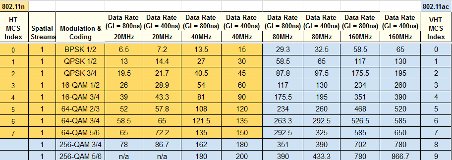
Note that some 802.11ac speeds are not supported (n / a). This is due to the distribution of information on the subcarriers: for some schemes, it is impossible to obtain an integer number of blocks, there remain extra bits. It was decided not to fill them, but simply not to use, because There are not many such speeds.
The 256-QAM modulation allows you to increase the speed by 33% (the number of bits per subcarrier has increased from 6 to 8). However, you need to understand that to work 256-QAM requires a good signal, the SNR should be at least 30dB. By the way, the new modulation "on the sly", some manufacturers have added for the 2.4 GHz band. Well, after all, we can now say that the 802.11n access point works at 800 Mb / s for four streams, instead of the standard 600 Mb / s (in fact, even 450 Mb / s, because 4 streams are also more exotic, although in the standard provided). Of course, such work will require a strictly defined client adapter, since this is not the standard.
Beamforming

Forming a beam pattern (transmit beamforming, TxBF) allows you to focus the transmitted signal towards the client, thus improving the downlink (channel from the access point to the client). The better the signal (the higher the SNR value), the faster we can transmit data to the client. The technology is relevant for access points with omnidirectional antennas. To calibrate the signal transmission for the array of antennas, the transmitter device (usually the access point) must first receive data from the receiver (client station). This can be either indirect information (service frames) or special calibration frames (they need to be generated on the receiver). The first option is called implicit beamforming (implicit beamforming), the second is explicit beamforming. An attempt to implement explicit beamforming was in the 802.11n standard, but the technology did not spread. Some manufacturers have implemented their own version with implicit beamforming support for 802.11 a / g / n devices. Ruckus uses BeamFlex technology for this. It is necessary to clarify that this is a more complex technology, including including beamforming. Ruckus access points use adaptive antennas that provide, in addition to beamforming, additional processing of the incoming signal, detuning from interference sources, etc. Cisco also has its own beamforming technology, ClientLink. Let us dwell on it in a little more detail.
Cisco ClientLink
In the case of ClientLink, only the access point is responsible for beamforming; support on the client is not required. At Cisco, this technology is implemented at the hardware level. It allows you to increase the signal level by 3-5 dB and optimally works with static clients.
ClientLink 1.0 for calibration uses the technology of Maximal Ratio Combining (MRC). In the MRC, the signal received at several antennas is shifted in phase and then added together to obtain a final incoming signal with a higher SNR. In ClientLink 1.0, based on the MRC algorithm, the access point remembers the phase and amplitude values for each 802.11a / g client. Next, the access point generates an outgoing signal from additional antennas to the client, based on this data, in order to obtain an improvement in the signal on the client. This is logical: if we send a signal in the same form as it was received, it will allow us to focus it in the direction we need, since in the opposite direction the signal will go the same way. It works automatically for the first 15 clients who connect to the access point.
ClientLink 2.0 supports beamforming for 802.11n clients with 1-3 spatial streams. The signal from the client access point is generated from all antennas. A superposition of spatial streams is transmitted to each antenna. The weighting factor calculation scheme is similar to ClientLink 1.0. Supports up to 128 clients.
The latest version of technology (ClientLink 3.0) has added support for 802.11ac clients. 80 MHz channels, 256-QAM modulation and up to three spatial streams are supported. Up to 128 customers are served. ClientLink 3.0, in addition to the standard work scheme (as in previous versions), also works in conjunction with the standard explicit beamforming in 802.11ac, which is described below.
802.11ac explicit beamforming
In 802.11ac, explicit beamforming is already implemented directly in the standard. It is planned that it will be supported massively on customers, however, as already mentioned, its presence is not mandatory. 802.11ac explicit beamforming only works for 11ac clients and is not compatible with other standards. At the same time, the client itself must also support explicit beamforming, since it is he who will inform the access point on how to transmit information.
The calibration process is as follows:
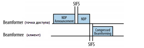
- The access point forms and sends a specialized frame (Null Data Packet Announcement - NDPA) to alert the client. It contains information on the number of transmitters, the number of streams and other related data.
- The Null Data Packet (NDP) is then sent to the client. This is done so that the client, analyzing the information in the headers at the physical level, could generate a report on the received signal and send it back to the access point.
- The client analyzes the signal received (on all antennas) for each subcarrier and generates a directivity matrix with a specific amplitude and phase. This matrix is quite large (especially considering the width of the channels at 11ac), so the answer is sent in a compressed form.
- The recipient (access point) on the basis of information received from the client generates a radiation pattern.
The formation of the radiation pattern occurs as follows: each antenna begins to transmit a certain superposition of all spatial flows with certain coefficients (phase, amplitude). And the coefficients for each stream on each antenna will be different.
It should be noted that the real gain from the technology of forming a pattern is obtained only if the number of antennas for transmission exceeds the amount of transmitted spatial streams.
For multi-user transmission (multi-user beamforming), the process is similar, but calibration takes place for each client individually.
Advanced MIMO
Multi-user MIMO (MU-MIMO) is one of the key innovations in 802.11ac. It allows you to split spatial streams and organize simultaneous data transfer to multiple clients (instead of transmitting only one client for regular MIMO at the same time). MU-MIMO works on wave 2 devices and is valid only for a downlink connection (from the access point to the client). Provided service no more than four users. Current access points support up to three users in MU-MIMO mode.
To implement this function, it was necessary to change the frame format at the physical level, by adding specialized headers to coordinate the parameters with several users. In addition, the division of a frame into recipients appeared (a frame addressed to all, a frame for a specific client).

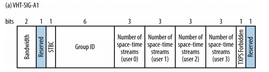
By the way, in 802.11n (HT) there are various frame formats (and access point operation modes): mixed - for compatibility with 802.11a / g / n devices or greenfield for only 11n devices. 802.11ac uses one universal format that includes 802.11a / ac headers.
How to transmit information simultaneously to all users? Here, beamforming properties help us. After calibration, each stream (or several streams) is sent to each user with its own radiation pattern. To prevent interference of the transmitted signal during multi-user transmission, the radiation pattern for each client is constructed in such a way that the signal for neighboring clients comes in antiphase. This is important, because the client must "hear" only the spatial stream that is addressed to him. Otherwise, spatial streams will affect each other, and the client will not understand anything. It is logical to assume that the technology does not work if the clients are at a sufficiently close distance to each other (although for a premise due to the reflections, the question of “close finding” clients to each other is rather difficult).

Accurate calibration is extremely important for such a transfer, so it happens several times more often than for a single-user transfer. But, as we remember, this mechanism requires the transfer of a sufficiently large amount of information, which increases channel utilization.
The access point should analyze which mode is best to use for transmission. At the moment, the technology is more relevant to work with multiple clients that support one stream. For other cases, it will be easier to use the normal MIMO mode and transmit several streams with a specific radiation pattern in turn. Since access points with MU-MIMO support have appeared on the market relatively recently, it is difficult to say how widespread this technology will be.
Features access to the environment and the use of channels
One of the key innovations of the 802.11ac standard is the emergence of wider channels. Channels with a width of 20 MHz are used in 802.11a / g, channels of 40 MHz have appeared in 802.11n. However, the use of 40 MHz channels is optional. Moreover, for the 2.4 GHz band, some manufacturers of wireless equipment even banned the use of 40 MHz channels on their devices, since too few free frequencies. The new standard operates in the 5 GHz band, which is less loaded and has more free frequencies. New, wider channels allow you to transfer more information per unit of time and save battery energy on devices.
So, on the one hand, new channel formats have appeared - 80, 160, 80 + 80 MHz wide. On the other hand, of course, such wide channels in the range we get much less as compared to the channels 20-40 MHz for 802.11n. In addition, each regulatory domain has its own frequency limits.
Variations with the available channels in different countries / regions.

In our country, the first part of the band, 5150-5350 MHz (UNII-1 and UNII-2) is allowed for use in rooms:

Since it turns out to allocate 1-2 channels at 160 MHz (we have one), for use it is more likely an option when installing one access point and a free range (for example, at home, still 5 GHz is more often free, while its radius of action is less than 2.4 GHz) for maximum speed. For the corporate segment, the “working” channels are 80 MHz wide. By the way, despite the possibility of using 160 MHz channels in wave-2 devices, the flagship wave-2 access points of the corporate segment do not support 160 MHz channels (Cisco 1850, Aruba 320, Ruckus 710). To use 160 MHz channels, there is still an option with the allocation of two non-adjacent channels of 80 MHz (80 + 80) in different parts of the range. It really allows to increase the number of channels (from 2 to 4 in Europe, for example), but for us it is still irrelevant (only two adjacent channels of 80 MHz).
Well, we use 80 MHz. However, we already have 11a / n clients that use 20 MHz channels (less often - 40 MHz). The good old RTS / CTS (Request To Send / Clear To Send) mechanism helps to negotiate with them, which allows you to avoid collisions during transmission and inform the other participants about the busy band. In order to determine which channels are occupied for transmission, the initiator sends an RTS frame on all 20 MHz channels from the wide channel planned for transmission. The recipient checks the accessibility of the environment (Clear-Channel Assessment, CCA) before sending the CTS response frame. If the broadcast is free, transmission begins. If a channel (or channels) is used, the CTS is transmitted only for free channels and transmitted to them (20 or 40 MHz, for example). Also, a mechanism for working together 802.11ac devices has been developed. For example, if there are two 802.11ac access points operating on the same 80 MHz channel, each of them divides it into two 40 MHz channels and determines the primary channel for transmitting traffic (for example, 36-40 and 44-48) and both transmit simultaneously, without waiting for the 80 MHz band to be freed. For example, in a particular case, the transfer might look like this:
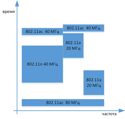
As far as you can see, the mechanism works quite flexibly; in addition, no new connection is required to switch the band, the rebuilding takes place in a per-packet mode.
Improvements introduced in the 802.11ac standard make it possible to reduce the load on the network (capacity has increased), make more optimal use of frequencies, and save energy on devices. The need to move to a new standard each defines itself. If your corporate wireless network is stable, 802.11a / g / n speeds are enough, then the new standard will wait (new 802.11ac client devices will connect at 802.11a / n speeds). If you use the 2.4 GHz band, it is loaded (many clients, neighboring networks) and the quality of service leaves much to be desired, perhaps the new standard (and generally the 5 GHz band) is just for you. Compared to 802.11n, 802.11ac dots (at least the first wave) are usually the same. I would also like to note that when planning a network, it is necessary to take into account the number of clients in the network, their speeds and throughput capabilities of current equipment (WLAN controllers, switches) for correct operation of the new standard.
Source: https://habr.com/ru/post/274267/
All Articles