Development of digital hardware in C ++ / SystemC through the eyes of the programmer SystemVerilog

SystemC is a library for C ++ that allows you to simulate various hardware systems at different levels of abstraction. It supports both traditional discrete event modeling, familiar to programmers on Verilog and VHDL, and analog modeling in the spirit of SPICE / Verilog AMS. The kit also includes a library and methodology for virtual prototyping, a library for writing test environments and verification using randomized tests.
In this article, I will talk about the synthesizable subset of SystemC, comparing it with synthesizable SystemVerilog. I myself have been using SystemC for about 3 years, and before that I had been writing on Verilog / SystemVerilog for several years. I will try to cover the subject from different angles: from philosophical discourse on the causes of SystemC, an overview of the ecosystem and tools, and ending with practical examples of syntax and semantics.
')
This implies that readers are familiar with Verilog and C ++.
Reflections on the causes of SystemC
Over its long history, the electronics development industry has found application to many programming languages and has spawned a huge number of domain-specific languages. If we imagine a hypothetical full-stack apparatchik (by analogy with a full-stack web programmer) who can single-handedly design a modern microcircuit, from an algorithm to implementation in silicon, then in addition to knowledge of the hardware (arychitecture computer, electronics, algorithms from and others) will have to own a whole bunch of different languages: Matlab for developing algorithms, Verilog or VHDL for describing RTL models, SystemVerilog / E / Vera for writing tests and test environments, TCL for writing scripts managing CAD packages, SPICE / Verilog-AMS for model tion analog subsystems, SKILL or Python for generating topologies, Cu / Asm for writing all kinds of firmware. If desired, the list goes on and on.
Of course, in nature, such universal engineers practically do not occur, and the project is made by several teams, each of which is well versed in its own rather narrow field. However, it is very often necessary to combine work at several stages of development. For example, it is easy to imagine that a person who wrote an RTL model of an IP block will write for him and a set of tests for verification. This in turn creates a request for the creation of universal languages suitable for solving related problems.
In the world of digital microelectronics, SystemVerilog has become such a universal language, which, apart from the classic Verilog (with small extensions), contains an object-oriented language for writing test environments, an assertions language for formal verification, as well as special constructions for randomization and analysis of test cover. In a sense, SystemVerilog is not a completely new language, but rather a conglomeration of languages, glued together with a common syntax.
But what if we want more? A language in which in addition to the above, you can develop algorithms, write firmware, create virtual prototypes. Is it time to add another DSL to SystemVerilog?

We need to go deeper
However, there is another approach: instead of inventing all new DSLs, you can create software libraries designed to solve a special class of problems. In this way, the creators of SystemC went - a library for C ++ that allows you to simulate digital equipment. Although in a sense SystemC is a DLS created by means of metaprogramming in C ++, C ++ itself is not extended with new syntactic constructions. Metaprogramming is widely used in other C ++ libraries.
This approach has its pros and cons. The main advantage of C ++ is its versatility: today you can write a hardware on SystemC, and tomorrow a GUI on Qt. (Although it will take a lot of time to study each of these libraries). The main minus in the syntax: the code on pure DSL will be much more beautiful, especially if you need to do something simple (for simple modules, the Verilog code will be smaller and simpler than the similar code on SystemC).
In addition to the lack of versatility, Verilog has another problem: it is very low-level. In a sense, synthesized Verilog is a macro-assembler for hardware (if an assembler for hardware is a logic circuit). New designs that appeared in the synthesized SystemVerilog do not solve this problem of low level. Very often, you have to resort to using all sorts of Verilog code generators, such as Python scripts . Among my colleagues, the idea of inserting Perl code inside Verilog modules was a popular idea. The hybrid thus obtained was called perlilogue. I think many are familiar with Verilog-mode for emacs , which can generate Verilog code for connecting modules.
Compared to SystemVerilog, synthesized by SystemC allows much more. Yes, you can write synthesized code with classes! When solving complex problems, the C ++ abstraction tools allow you to write more elegant (simple and compact) code.
SystemC Ecosystem
Consider the basic software tools that developers on SystemVerilog and SystemC have to deal with.
Development environment
SystemVerilog:
Most Verilog programmers use a text editor to write code: Verilog support is found in Vim, Emacs, Sublime Text, Notepad ++, Slickedit, and other popular editors. Writing code in a test editor may seem archaic to application programmers: most of them use smart IDEs with auto-prompts, automated refactorings, and easy navigation. However, in the world of synthesized Verilog there is no great benefit from the use of IDE: this is explained by the fact that all the functionality is divided into completely independent modules. The whole context with which the developer of a separate module works usually fits into one file. Quite another thing with writing testbenches on SystemVerilog, an IDE such as DVT may be useful here.
SystemC:
When writing a synthesized C ++ / SystemC simple text editor is not enough. Fortunately, there are many C ++ IDEs (including free ones) that can handle SystemC code. For example, you can use the familiar to many MS Visual Studio . I have used Eclipse CDT and Netbeans for a long time to write C ++ / SystemC code. Last time I try Clion from Jetbrains .
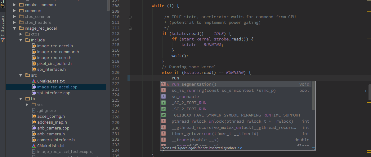 Writing SystemC Code in Clion
Simulation and debugging
SystemVerilog:
To simulate and debug code on Verilog, an HDL simulator is used. There are both free (IcarusVerilog) and paid simulators. Compared to a free simulator, commercial solutions provide faster simulation speeds and provide convenient graphical environments for debugging.
SystemC:
With SystemC, the situation is generally similar: you can use the reference simulator and GDB for debugging, but when you need to debug some more or less complex signaling protocol, you have to use one of the commercial simulators.

Debugging SystemC in the simulator
Synthesis
SystemVerilog:
Synthesis of SystemVerilog is supported by major FPGA and ASIC vendors. There are also free versions of packages for FPGA, which are used by many Russian universities for teaching students the basics of digital circuitry.
SystemC:
For SystemC synthesis, special high-level synthesis packages (HLS) are used. What in them such a high-level you ask? The thing is that HLS packages, in addition to traditional RTL code written on SystemC, can also synthesize purely behavioral (“untimed”) code, automatically inserting registers where necessary.
Most HLS packages can synthesize pure C / C ++, SystemC is used only in cases where you need to add modularity and signaling interfaces. In a sense, synthesis with C / C ++ is a technology for developing accelerators that competes with synthesis with OpenCL . Although using SystemC, we are not limited only to the development of accelerators, but we can develop completely any digital circuits. A little later, I will talk about HLS a little more.
At the output of the HLS package, we usually have the usual RTL modules on Verilog, which are then synthesized using the Verilog synthesizer.
Unfortunately, all existing HLS with SystemC support are purely commercial and cost a lot of money. There are no free versions, although universities sell everything at a big discount.
The best means of synthesizing SystemC on the market are Stdence from Cadence and Catapult C from Calypto / Mentor Graphics .
Other EDA packages for SystemC
In addition to writing synthesized code, SystemC is widely used for virtual prototyping. The creation of virtual prototypes (emulators) on the C ++ / SystemC is used in the packages Synopsys Virtualizer , Mentor Graphics Vista , Cadence Virtual System Platform . At the same time, we cannot say that SystemC is the dominant solution in this market: there are also SystemC products that do not use, for example, WindRiver Simics .
This concludes the article. It's time to dive into the code.

Dive into code
Synthesized SystemC. Base building blocks
I will not fully describe the entire SystemC standard here, I will go over only the most necessary. All examples will be built on a comparison of SystemVerilog and SystemC.
Data types
SystemVerilog:
The main type used in the synthesized SystemVerilog is the type of logic . A variable of the type logic can take 4 values: 1, 0, x, z. x means unknown value. z means high impedance state. You can create logic type vectors of various lengths, for example:
logic [1:0] data; // 2- initial begin data = 7; $display(data); end SystemC:
In SystemC, there are also types with 4 states. However, in practice, types with 2 states 1 and 0 are mainly used. The main reason is that types with 2 states are simulated faster.
After synthesis, all types with 2 states turn into logic. This can lead to differences in the results of SystemC simulations (before synthesis) and Verilog (after synthesis). In SystemC, an unset register will have the value 0, in Verilog - x. Fortunately, the synthesizer issues a warning every time it sees a register without a reset, so in practice, after reading the synthesizer log, problems with divergence of the simulation results can be avoided.
Very often, C code on the SystemC uses built-in C ++ types, such as int or char. If we need a number with a specified number of bits, we can use the type sc_uint:
sc_uint<2> data; // 2- data = 7; cout << data; Will output to console: 3How is sc_uint implemented? This is just a template class in which all major operators are overloaded.
Modules
Consider the example of an empty module on SystemVerilog and SystemC
SystemVerilog:
module top ( input clk, rstn, input [7:0] din, output logic [7:0] dout ) // endmodule SystemC:
struct top: public sc_module { sc_in<bool> clk, rstn; sc_in<sc_uint<8> > din; sc_out<sc_uint<8> > dout; top(const char* name) : sc_module(name) , clk("clk") , rstn("rstn") , din("din"), dout("dout") { } }; Let us examine the interesting lines in more detail: struct top: public sc_module { modules in SystemC are derived classes from the sc_module class sc_in<bool> clk, rstn; sc_in<sc_uint<8> > din; sc_out<sc_uint<8> > dout; To create ports in SystemC, the special classes sc_in and sc_out are used. top(const char* name) : sc_module(name) , clk("clk") , rstn("rstn") , din("din"), dout("dout") Module and port constructors are passed strings containing their name. This is necessary for the simulation core to produce easy-to-read logs, for example:Error: (E109) complete binding failed: port not bound: port 'top.dout' (sc_out): dout top .(Probably, when normal introspection support appears in C ++, objects in SystemC will be able to recognize their names on their own)
For the convenience of creating modules in SystemC, several macros are defined. Using them, a similar module looks like this:
SC_MODULE(top) { sc_in<bool> clk, rstn; sc_in<sc_uint<8> > din; sc_out<sc_uint<8> > dout; SC_CTOR(top) , clk("clk") , rstn("rstn") , din("din"), dout("dout") {} }; Variables and Assignments
SystemVerilog:
It can be argued that all the variables in the synthesized SystemVerilog are static: they exist from the beginning to the end of the simulation. And they have a global scope (although access to the signals “through the roof” by the hierarchical name is not allowed in the synthesized code). Another feature of SystemVerilog is the presence of several assignment operators: blocking and non-blocking assignments in procedural blocks, as well as continuous assignments.
The blocking assignment occurs either immediately or blocks the execution of the current process until the moment when the assignment is completed.
Example:
logic a; initial begin a = #42 1; $display($time); end Will output to console: 42because The call to the $ display function will occur only at time 42, when assignment will occur.
Non-blocking assignment defers assignment at some point in the simulation time in the future and does not block the execution of the process. If time is not specified explicitly, assignment occurs on the next delta cycle.
initial begin a <= #42 1; $display($time); end Will output to console: 0SystemC:
Variables in C ++ do not know anything about the SystemC simulation kernel and therefore behave in a way familiar to a C ++ programmer. In order to simulate non-blocking assignment in SystemC, a special type of sc_signal is used, variables of this type are referred to below as signals:
sc_signal< sc_uint<2> > data; // sc_uint<2> Any assignment of the data value will be non-blocking.Synthesized SystemC requires that the interaction between multiple processes takes place through signals. Similarly, in Verilog, a good style is to use exclusively non-blocking assignments in always_ff procedural blocks. Otherwise, we risk to get an indefinite behavior (race condition) when the simulation result will depend on the order of calling the processes in one delta cycle.
There is no blocking assignment analog in SystemC.
Processes (Procedural blocks)
SystemVerilog:
Synthesized SystemVerilog supports two main types of procedural blocks always_comb and always_ff. In addition to them, there is always always_latch, but in practice it is quite rare to use latch registers.
always_comb is used to describe combinatorial logic.
always_comb begin a = b + c; end The process will be executed each time the value of b or c changes. The same could be written more explicitly, as in the classic Verilog: always@(b or c) begin a = b + c; end In addition to the always_comb procedure block, a continuous assignment operator can be used to describe combinational circuits: assign a = b + c; The procedural block always_ff is used to describe sequential logic, i.e. circuits with memory. always_ff @(posedge clk or negedge arst_n) begin if(~arst_n) begin a <= 0; end else begin a <= a + 1; end end This example describes a binary counter with asynchronous reset.SystemC:
Processes in SystemC are created in the module constructor. The body of the processes is described in the member functions of the module. The type of process that always looks like a block from Verilog in SystemC is called SC_METHOD.Consider examples of processes similar to the procedural blocks shown earlier on SystemVerilog:
Combinatorial logic:
SC_CTOR(top) { SC_METHOD(comb_method); // SC_METHOD sensitive << b << c; // ( @(a or b) ) } void comb_method() { a = b + c; } // - Sequence logic: SC_CTOR(top) { SC_METHOD(seq_method); // SC_METHOD sensitive << clk.pos() << arst_n.neg(); // ( @(posedge clk or negedge arst_n) ) } void seq_method() { // - if (!arst_n) a = 0; else a = a + 1; } There is no analogue of continuous assignment in SystemC. Just as there is no possibility to specify the wildcard in the sensitivity list (always @ * in Verilog). Even the powerful template magic of C ++ does not allow this to be implemented by means of metaprogramming.Parameterization
Modules on SystemVerilog can be parameterized. For example, you can write a parameterized FIFO, the width and depth of which will be specified when creating an instance.
In SystemC, template classes are used to create parameterizable modules. With the use of patterns and inheritance, the parameterization possibilities in SystemC become almost limitless.
Subtotals
SystemC allows you to describe hardware at the RTL level in a style very close to simple Verilog. The Verilog code will be sleeker and more compact, but in general, all the functionality can be repeated. Consider a full-fledged example: let's implement a shift register with serial input and output (serial-in / serial-out) and asynchronous reset on Verilog and SystemC:
Verilog code:
module shifreg ( input clk, sin, reset, output sout ); reg [7:0] tmp; always @(posedge clk or posedge reset) begin if (reset) tmp <= 0; else tmp <= {tmp[6:0], sin}; end assign sout = tmp[7]; endmodule Code on SystemC // C++11 SC_MODULE(shift_reg) { sc_in<bool> clk{"clk"}, sin{"sin"}, reset{"reset"}; sc_out<bool> sout{"sout"}; SC_CTOR(shift_reg) { SC_METHOD(shift_method); sensitive << clk.pos() << reset.pos(); // .. , SC_METHOD(sout_method); sensitive << tmp; } private: sc_signal <sc_uint<8> > tmp {"tmp"}; void shift_method() { // read write // write - verilog if ( reset.read() ) { tmp.write(0); } else { // "," () tmp.write((tmp.read().range(6,0) , sin.read())); } } void sout_method() { sout = tmp.read()[7]; } }; Good systemc. Opportunities synthesized SystemC, which are not in SystemVerilog
User Data Types
Synthesized SystemC fully supports C ++ object-oriented programming. This allows you to create convenient data types for work in your subject area. For example, if you are engaged in 3D graphics, then you constantly have to deal with 3-dimensional real vectors. For their hardware implementation will need to solve several problems.
First, floating point operations are generally not supported by the synthesizer. Therefore, you will have to implement them yourself, or use a third-party library, such as DesignWare floating point. In either case, you can create a convenient class for working with a floating point:
class my_float { public: my_float operator+( const my_float &rval) const; my_float operator-( const my_float &rval ) const; my_float operator*( const my_float &rval ) const; // ... private: sc_uint<32> raw_data; // float 32- } Using my_float, you can implement a class for working with vectors: class vector_3d { public: vector_3d operator*( const vector_3d &rval ) const; // vector product vector_3d dot_product (const vector_3d &other) const; // dot product // ... private: my_float x, y, z; }; Then these custom types can be used in the synthesized SystemC. vector_3d a,b,c; c = a + b; SystemVerilog synthesizers do not support class synthesis, but are able to synthesize structures. Therefore, programming on SystemVerilog is somewhat similar to C programming. On SystemVerilog, this problem with vectors is usually solved as follows: you create a separate package, and in it you define structures and functions for working with them: package Vector3DPkg; typedef struct { logic [31:0] x, y, x; } vector_3d; function vector_3d add(vector_3d a, b); add.x = float_add (ax, bx); add.y = float_add (ay, by); //... endfunction function vector_3dmul(vector_3d a, b); //.... endpackage : Vector3DPkg SC_CTHREADS (clocked threads). Processes with implicit state
Synthesized processes in Verilog cannot use expressions to control time and wait for events. Those. A running process must be executed to the end and only then transfer control to another process. For example, this process is not synthesized:
always @(posedge clk) begin out <= 1; @(posedge clk); // out <= 2; @(posedge clk); out <= 42; end In Verilog, we need to explicitly specify a state register that will determine the behavior of the process at each tick. The following process will be the synthesized analogue of the previous code example: logic [1:0] state; always @(posedge clk or negedge reset_n) begin if ( ~ reset_n) state <= 0; out <= 1; else case (state) 0: begin state <= 1; out <= 1; end 1: begin state <= 2; out <= 2; end 2: begin state <= 0; out <= 42; end end In SystemC, synthesized processes describing sequential logic (digital automaton) can stop waiting for an event from a clock signal. This allows the machine to be described without explicit specification of the status register. Processes of this type are created using the SC_CTHREAD macro. The process is stopped until the next clock signal by calling the function wait (); Example: SC_CTOR ( top ) { // // clk.pos() clk SC_CTHREAD(test_cthread, clk.pos() ); async_reset_signal_is(reset_n, 0); // 0 } void test_cthread () { // wait() reset-, . out <= 1; wait(); // SC_METHOD, SC_CTHREAD // while (1) { out.write(1); wait (); // clk out.write(2); wait (); // clk out.write(42); } } At first glance, the benefits of having such processes are not obvious. In the end, it is not so difficult to explicitly encode a variable for the state of the digital automaton (the state variable in the example on Verilog).The true power of SC_CTHREAD processes is the ability to call functions that can block a process, i.e. call the wait () function. Such a function can be performed several cycles! Analogous from the world of Verilog are the tasks, but they are not synthesized and are used only in tests.
For example:
while (1) { res = calculate_something(); // - spi_send(res); // SPI, } Even more useful for functions, the execution of which sometimes takes several cycles, and sometimes it happens instantly, without calling wait ().For example, consider a process that reads data from a FIFO, processes it, and then sends the result to memory via the system bus (for example, AMBA AXI). Let the data be a 3-dimensional vector considered earlier, and the processing will be to normalize this vector. Using SC_CTHREAD and ready-made classes for working with FIFO and AXI, writing such a process is very simple:
fifo data_fifo; // FIFO amba_axi bus_master; // AMBA AXI void computational_thread() { wait(); while (1) { vector_3d vec = data_fifo.pop(); // FIFO vec.normalize(); // bus_master.write( 0xDEADBEEF, vec); // 0xDEADBEEF } Suppose that the normalization of a vector is implemented as a combinational circuit. Then, depending on the readiness of the FIFO and the bus, the execution of one cycle of such a process can take from one clock cycle or more. If there is data in the FIFO and the bus is not busy, then normalization of one vector will occur per clock. If the FIFO is empty, then the process will be blocked for reading from the FIFO data_fifo.pop until the new data is received. If the bus is busy, the process will be blocked on the bus_master.write function until the bus is free.An experienced developer probably had a question, how do we normalize the vector per clock? At what frequency does our module work? Indeed, a chain of multiplication, two additions, a square root and division is too much for one combinational circuit. Especially since we are talking about floating point operations. In the case of synchronous circuitry, this combination chain is likely to become a bottleneck, limiting the maximum clock frequency of the entire circuit.

Depending on the bandwidth requirements of our normalizer, the problem can be solved in several ways:
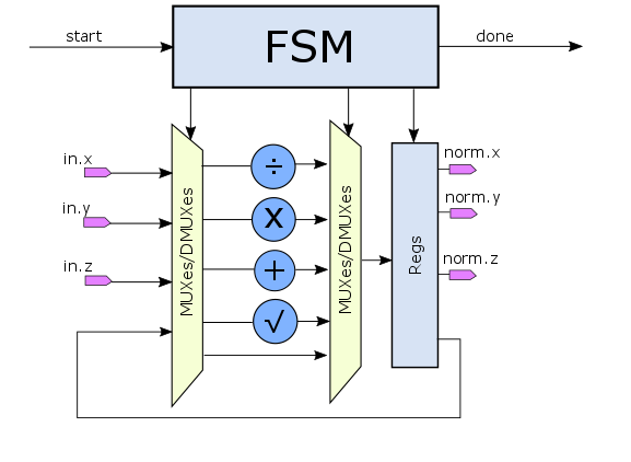
- If we are not in a hurry, we can save on resources and implement normalization in the form of FSMD with one multiplier, adder, divider and square root module. In this case, we will spend 6 clocks to calculate the length of the vector and another 3 clocks to calculate the value of each of the elements of the result, in total - 9 clocks per vector.
- If we are in a hurry and resources are not sorry, the original combinational circuit can be turned into a pipeline. In this case, at the peak (when there is always data in the FIFO) we get the same 1 clock per vector, but at a higher clock frequency.

- Any intermediate between the first and second variants are also possible. For example, if the logic is expensive and the registers are cheap, then in the first considered variant of the micro-architecture, you can begin processing the next vector without waiting for the completion of the previous one, as resources become available. After calculating the three squares of the elements of the first vector, the multiplier is released and you can begin processing the next vector. Such an implementation is called a pipeline with an initialization interval of 3 cycles. Those. every three cycles the pipeline will pick up a new vector from the FIFO.
Unfortunately, the implementation of any of the proposed solutions manually will require a lot of time and will significantly complicate our 3-line source. For example, in the case of a pipeline implementation, you will have to create a process for each of the stages of the pipeline. Fortunately, when using SystemC, we don’t need to do anything with our hands - after all, you can simply use high-level synthesis!
High-level synthesis.
High-level synthesis is the process of transforming an algorithmic code written in a high-level programming language into digital equipment that implements it. At the input of the HLS packet are:
- Source. Sometimes it is called untimed code, because it contains no constructs to stop the process, such as the wait function
- Timing constraints. Temporary restrictions. Set the list of clock signals and their period, as well as delays on external ports
- Specification microarchitecture. As a microarchitecture, we can choose any of the previously considered options
void vector_3d::normalize() { my_float magnitude = sqrt( x*x + y*y + z*z ); x = x / magnitude; y = y / magnitude; z = z / magnitude; } As a micro-architecture, you can, for example, select a pipeline with an initialization interval of 1 clock and a latency of 4 clock cycles, and a clock frequency of 500 MHz. Using the technology library HLS package will determine the delay of signal propagation through each arithmetic element and optimally arrange them into stages of the conveyor. If necessary, the execution of a single operation can be divided into several stages: for example, a division is a rather complicated operation, the execution of which may not fit into one clock period. Therefore, it is quite possible that the synthetor will split the divider between the 3rd and 4th stage of the pipeline.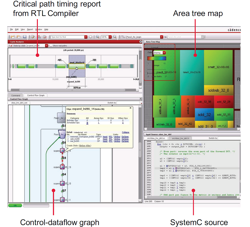
Analysis of the project in the HLS package from Cadence
Experienced users of logic synthesis tools know that some of them (for example, the Deisgn Compiler) have a similar function called retiming. Compared with retyming, HLS has several advantages:
- There is no need to specify the registers, the logic of the pipeline stop.
- HLS allows you to switch between multiple micro-architectures without changing the source code.
uint32_t write_address; // 32- vector_3d memory[1024]; // 1024x96 , - 96 .... while (1) { vector_3d vec = data_fifo.pop(); // FIFO vec.normalize(); // memory [write_address] = vec; // write_address ++; } I would also like to note that not all HLS tools support synthesis with SystemC. Using SystemC is required only where it is necessary to describe signal interfaces (for example, AMBA or UART). On FPGA platforms, bus interfaces are typically standardized, so their use in the HLS code may be implicit. For example, Vilado HLS from Xilinx is primarily focused on synthesis from pure C / C ++. As part of the Xilinx SoC platform, the standard is the AMBA AXI interface, so it is assumed that your functions will be sent and received via AXI, or using a simple handshake protocol. All that is required of you is to describe the algorithmic code. Of course, this approach also has its drawbacks: when creating complex projects, you may well come to pasting many HLS modules in the code on Verilog or the graphical editor of schemes.For these purposes, Xilinx has another product - Vivado IP Integrator.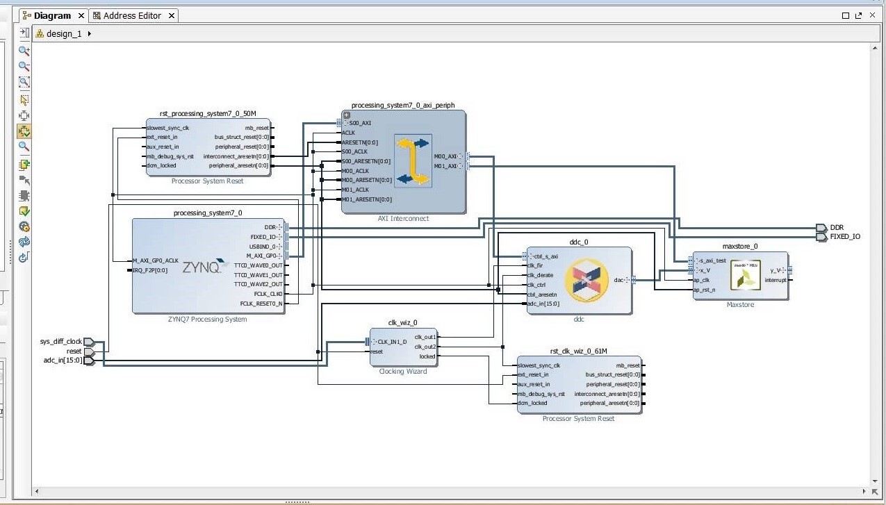
Connecting the HLS unit to the ARM processor via AMBA AXI in Vivado IP Integrator
Conclusion
As a conclusion, I want to try to answer the question that is often asked by RTL developers after seeing the new tool: And what about the quality of the result? How will the timings, area, power consumption of the circuits described on SystemC and synthesized using HLS compared to the RTL described on SystemVerilog differ?
Actually nothing. Everything is in your hands: SystemC and HLS do not deprive you of the opportunity to zatyunit everything up to the gate where it is required. And at the same time, HLS does not release you from the need to understand the basics of digital circuitry. HLS is not a magic tool that turns a C ++ programmer into an apparatchik, it is a tool that allows you to automate routine work, facilitating the process of writing and maintaining the synthesized code.
In this article, I did not touch on the question of verification. Verification always takes most of the development time and SystemC has something to offer in this field. Well-written SystemC is stimulated faster than RTL, because part of the code is written in the “untimed style”, and signal interfaces can be replaced with function calls (Transaction-level modeling). The SCV (SystemC Verification Library) library allows you to randomize test vectors, also on the approach of SystemC version of UVM. And sinceSystemC is C ++, parts of the source code can be reused between the synthesized code, the reference model, the virtual prototype and the operating system driver. But the story about all this is worthy of a separate article.
Source: https://habr.com/ru/post/274137/
All Articles