RC Car with GPS on Arduino Nano
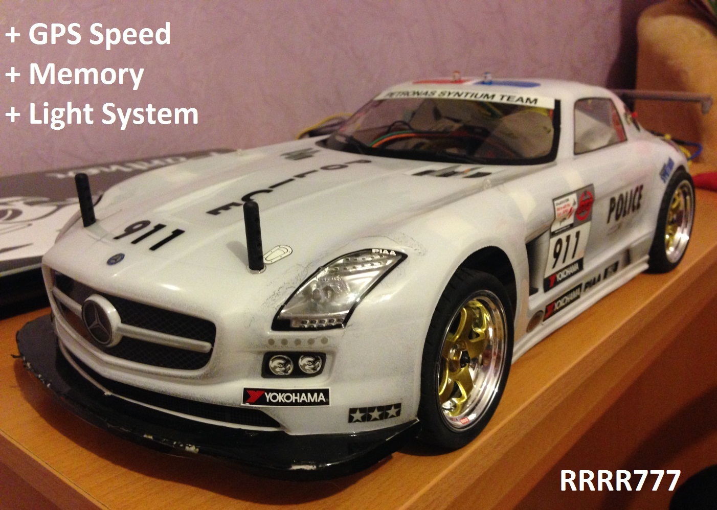
My idea: find out the maximum speed in a radio-controlled typewriter and memorize when turning off the power, add headlights when speeding up, turning on turn signals when turning, turning on stop signals when braking, turning on the parking lights, flashing lights when pressing a button on the typewriter (reset button for maximum speed) .
The machine, which is used in the configuration:
- Servo Drive "HARD HS3004"
- Engine "Leopard 4370KV";
- Regulator for the engine "Leopard V2"
- Battery "Li-Pol 7,2V 30C 5000mA";
- Receiver "2,4Ghz" 3 channels;
- 2.4Ghz Digital Proportional R / C system control panel
The task to do on having a typewriter:
- Install all lights and button
- Install arduino hardware
- Download the program in Arduino
- Program setting
Installing lights of light. I took the finished LEDs with wires from the RC Car Flashing Light System kit.
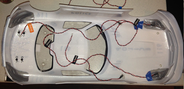
Installing the headlights (they are also the dimensions) and turn signals
')
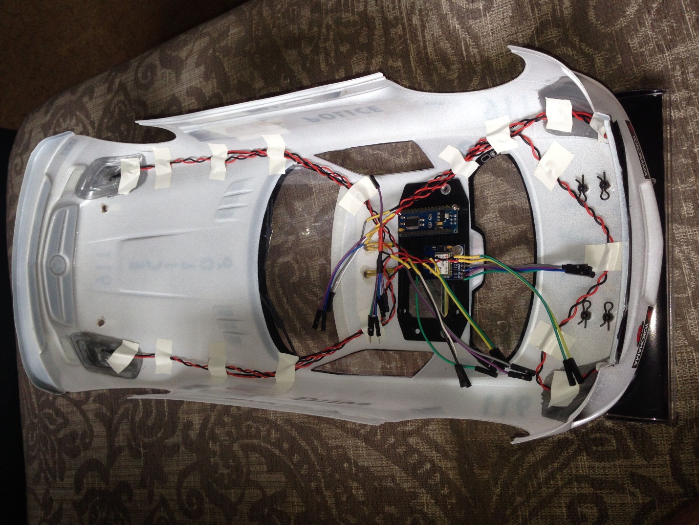
Installation of the equipment Arduino Nano and GPS, all secured with double sided tape and screws
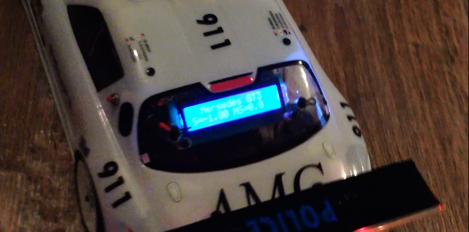
Installing the LCD on the rear window, fastened with screws
What you need to build:
Arduino Nano, price from 200 r.
GPS receiver, price from 900 r.
LEDs, price from 100 p. White LEDs, 3 pcs. (headlights and reverse), red 2 pcs. (brake), orange 2 pieces. (turn signals)
Wires, price from 100 r.
LCD and I2C, price from 200 r.
Button and resistor, price from 100 r. / Button (resetting the speed and turning on the flashing lights) and 10 kΩ resistor
The price of the project turned out 1600 rubles.
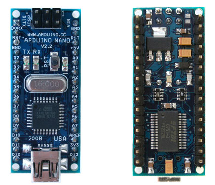
1. Arduino Nano
2. LCD 1602 and I2C
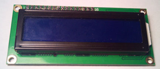
LCD
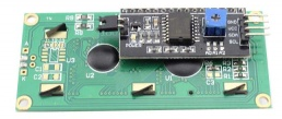
LCD backside and solder an I2C module to it
3. GPS-GY-NEO-6MV2 (GPS receiver)
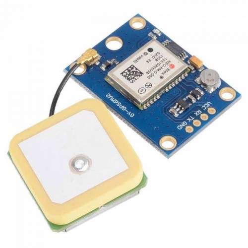
GPS receiver
Install the program for arduino in the computer and upload the sketch to arduino.
If the library is not enough, then you need to download and install them on your computer: LiquidCrystal_I2C.h, EEPROM.h, Wire.h, SoftwareSerial.h, TinyGPS.h.
The sketch itself:
SKETCH
#include <EEPROM.h>
#include <Wire.h>
#include <LiquidCrystal_I2C.h>
LiquidCrystal_I2C lcd(0x27, 16, 2); //I2C: SDA pin A4 / SCL pin A5 /VCC pin +3,3V /GND pin GND
#include <SoftwareSerial.h>
#include <TinyGPS.h>
TinyGPS gps;
SoftwareSerial ss(4, 3); // GPS: RX pin D4, TX pin D3, VCC pin +5V ,GND pin GND
static void smartdelay(unsigned long ms);
static void print_float(float val, float invalid, int len, int prec);
static void print_int(unsigned long val, unsigned long invalid, int len);
static void print_date(TinyGPS &gps);
float flat, flon; //
unsigned long fix_age, time, date, speed, course; //
int value;
int value2;
int pin = 7; // D7
int pins = 8; // D8
int pin1 = 11;// : D11
int pin2 = 12;// : D12
int pin3 = 10;// : D10
int pin4 = 9;// : D9
int pin6 = 6;// : D6
unsigned long duration1;// 1372 , 1834 ,973
unsigned long duration2;// 1834 , 973
int pin7 = 2;// : pin D2
int pin8 = 13;// pin D13
const int buttonPin = 5; // () , pin D5
int buttonState = 0; //
void setup()
{
pinMode(pin, INPUT);
pinMode(pin1, OUTPUT);
pinMode(pin2, OUTPUT);
pinMode(pins, INPUT);
pinMode(pin3, OUTPUT);
pinMode(pin4, OUTPUT);
pinMode(pin6, OUTPUT);
pinMode(pin7, OUTPUT);
pinMode(pin8, OUTPUT);
pinMode(buttonPin, INPUT); // , ,
Serial.begin(115200); //
ss.begin(9600); //gps
Serial.println("RRRR777");
lcd.init(); //
lcd.clear();
lcd.backlight();
lcd.setCursor(0, 0);
lcd.print("RRRR777 2015");
lcd.setCursor(0, 1);
lcd.print(" GPS RCavto");
digitalWrite(pin7, HIGH); //
digitalWrite(pin8, LOW); //
delay(500); //
digitalWrite(pin8, HIGH); //
digitalWrite(pin7, LOW); //
delay(500); //
digitalWrite(pin7, HIGH); //
digitalWrite(pin8, LOW); //
delay(500); //
digitalWrite(pin8, HIGH); //
digitalWrite(pin7, LOW); //
delay(500); //
digitalWrite(pin7, HIGH); //
digitalWrite(pin8, LOW); //
delay(500); //
digitalWrite(pin7, HIGH); //
digitalWrite(pin8, LOW); //
delay(500); //
digitalWrite(pin8, HIGH); //
digitalWrite(pin7, LOW); //
delay(500); //
digitalWrite(pin7, HIGH); //
digitalWrite(pin8, LOW); //
delay(500); //
digitalWrite(pin8, HIGH); //
digitalWrite(pin7, LOW); //
delay(500); //
digitalWrite(pin7, HIGH); //
digitalWrite(pin8, LOW); //
delay(500);
digitalWrite(pin7, LOW); //
digitalWrite(pin8, LOW); //
delay(500); //
lcd.clear();
delay(500);
}
void loop()
{
duration1 = pulseIn(pin, HIGH);
duration2 = pulseIn(pins, HIGH);
if ((duration1 > 1500) && (duration1 < 2000))
{digitalWrite(pin1, HIGH); // LEFT
delay(250); //
digitalWrite(pin1, LOW); //
}
if ((duration1 < 1300) && (duration1 > 800))
{digitalWrite(pin2, HIGH); // RIGHT
delay(250); //
digitalWrite(pin2, LOW); //
}
if ((duration2 > 1480) && (duration2 < 2000))//
{ analogWrite(pin4, 20); //
analogWrite(pin3, 255); //
delay(500); //
}
if ((duration2 < 1480) && (duration2 > 800)) //
{analogWrite(pin4, 255); //
analogWrite(pin3, 20); // +*
digitalWrite(pin6, LOW); //
delay(50);
}
if ((duration2 < 1400) && (duration2 > 800))//
{//digitalWrite(pin4, LOW); //
digitalWrite(pin6, HIGH); //
delay(500); //
}
float flat, flon;
unsigned long age, date, time, chars = 0;
unsigned short sentences = 0, failed = 0;
float h = gps.f_speed_kmph(); // speed in km/hr
int h1 = (h-(int)h)*100;
Serial.println(h);
lcd.clear();
lcd.setCursor(0, 0);
lcd.print(" Mersedes GT3"); //
lcd.setCursor(0, 1);
lcd.print("S=");
lcd.print(h);
lcd.setCursor(8, 1);
lcd.print("MS=");
value = EEPROM.read(0); //
value2 = EEPROM.read(1);
lcd.print(value);
lcd.print(".");
lcd.print(value2);
buttonState = digitalRead(buttonPin);//
if (buttonState == HIGH)// LOW) ///
{
EEPROM.write (0,0);
EEPROM.write (1,0);
lcd.setCursor(8, 1);
lcd.print("MS=RESET");
digitalWrite(pin7, HIGH); //
digitalWrite(pin8, LOW); //
delay(500); //
digitalWrite(pin8, HIGH); //
digitalWrite(pin7, LOW); //
delay(500); //
digitalWrite(pin7, HIGH); //
digitalWrite(pin8, LOW); //
delay(500); //
digitalWrite(pin8, HIGH); //
digitalWrite(pin7, LOW); //
delay(500);
lcd.setCursor(0, 1);
lcd.print("Rusticktigr777@mail.ru");
digitalWrite(pin7, HIGH); //
digitalWrite(pin8, LOW); //
delay(500); //
digitalWrite(pin8, HIGH); //
digitalWrite(pin7, LOW); //
delay(500); //
digitalWrite(pin7, HIGH); //
digitalWrite(pin8, LOW); //
delay(500); //
digitalWrite(pin8, HIGH); //
digitalWrite(pin7, LOW); //
delay(500); //
digitalWrite(pin7, HIGH); //
digitalWrite(pin8, LOW); //
delay(500);
digitalWrite(pin8, HIGH); //
digitalWrite(pin7, LOW); //
delay(500); //
digitalWrite(pin7, HIGH); //
digitalWrite(pin8, LOW); //
delay(500); //
digitalWrite(pin8, HIGH); //
digitalWrite(pin7, LOW); //
delay(500); //
digitalWrite(pin7, HIGH); //
digitalWrite(pin8, LOW); //
delay(500);
digitalWrite(pin7, LOW); //
digitalWrite(pin8, LOW); //
}
if (h > value)//RECORD
{
EEPROM.write (0,h);
EEPROM.write (1,h1);
}
smartdelay(500);
}
static void smartdelay(unsigned long ms)
{
unsigned long start = millis();
do
{
while (ss.available())
gps.encode(ss.read());
} while (millis() - start < ms);
}
static void print_float(float val, float invalid, int len, int prec)
{
if (val == invalid)
{
while (len-- > 1)
Serial.print('*');
Serial.print(' ');
}
else
{
Serial.print(val, prec);
int vi = abs((int)val);
int flen = prec + (val < 0.0 ? 2 : 1); // . and -
flen += vi >= 1000 ? 4 : vi >= 100 ? 3 : vi >= 10 ? 2 : 1;
for (int i=flen; i<len; ++i)
Serial.print(' ');
}
smartdelay(0);
}
static void print_int(unsigned long val, unsigned long invalid, int len)
{
char sz[32];
if (val == invalid)
strcpy(sz, "*******");
else
sprintf(sz, "%ld", val);
sz[len] = 0;
for (int i=strlen(sz); i<len; ++i)
sz[i] = ' ';
if (len > 0)
sz[len-1] = ' ';
Serial.print(sz);
smartdelay(0);
}
static void print_date(TinyGPS &gps)
{
int year;
byte month, day, hour, minute, second, hundredths;
unsigned long age;
gps.crack_datetime(&year, &month, &day, &hour, &minute, &second, &hundredths, &age);
if (age == TinyGPS::GPS_INVALID_AGE)
Serial.print("********** ******** ");
else
{
char sz[32];
sprintf(sz, "%02d/%02d/%02d %02d:%02d:%02d ",
month, day, year, hour, minute, second);
Serial.print(sz);
}
print_int(age, TinyGPS::GPS_INVALID_AGE, 5);
smartdelay(0);
}
Connecting wires to Arduino:
Wires
I2C: SDA pin A4 / SCL pin A5 / VCC pin + 3.3V / GND pin GND (set maximum brightness and backlight)
GPS: RX pin D4, TX pin D3, VCC pin + 5V, GND pin GND
Reset button (normally open button): one pin VCC pin + 5V, another pin on pin D5, resistor on pin D5 and pin GND
LEDs: Front headlights (dimensions) white “+” on pin D9
LEDs: Rear lights (dimensions) red "+" on pin D10
LED: Reverse white "+" on pin D6
LEDs: Front headlights (dimensions) white “+” on pin D9
LED: Turn left orange "+" on pin D11
LED: Turn right orange "+" on pin D12
LED: Blinker red "+" on pin D2
LED: Blue light "+" on pin D13
For all LEDs "-" on the pin GND
We connect the wire for turn signals on the pin D7 from the entrance of the servomotor turns (the three wires are usually white to him and let the wire go to pin D7, the red one is power plus, the black one is power minus, it is connected to the receiver).
We connect the wire for movement on the pin D8 from the engine servo input (three wires: usually it is white, we feed the wire to it and output the wire to pin D8, the red one is powered plus, the black one is powered minus, it is connected to the receiver).
Power for the Arduino is taken directly from the battery "+" on the pin VIN (in my 7.2v). GND common wire for Arduino straight from the battery "-".
Setting: if it does not work correctly when turning or moving, then we change the values to our own through the program on the computer: in the lines if ((duration> ) && (duration <)) if the data is not processed and the green LED on the GPS, TX card is on / RX may need to swap RX pin D4, TX pin D3,)
PS The idea was simple, knowing the programming, you can also add to this machine the temperature in the engine and alert about it, add the hour, tachometer and video camera on the Mercedes-Benz GT3.
Good luck to all!
Source: https://habr.com/ru/post/273871/
All Articles