Networks for the smallest. Part eleven. MPLS L3VPN
Last time we left no stone unturned when parsing MPLS. And this is probably good.
But so far, only real-life application of it is drawn. And that's bad.
This article will begin to correct the situation. In general, the reader is waiting for a series of three articles: L3VPN, L2VPN, Traffic Engineering, where we will try to fully tell why MPLS is needed in practice.
')
So, linkmeup is no longer an outsourcing of support for a large but single company, we are a provider. You can even say the federal provider, because our optics leads to all parts of the country. And our numerous clients want not only high-speed Internet access, they want VPN.
Today we will understand what will have to be done on our network (on which MPLS is already set up in the meantime) in order to satisfy these rampant appetites.

Traditional video:
How to organize the interaction of two remote sites on the Internet? Very simple, if they have public addresses - the IP for this was invented. They can communicate directly. In any case, to connect two points on the Internet, you need two public addresses - one on each side. And if we have private addresses (10/8, 172.16 / 20, 192.168 / 16)?
Then they will "pull on" on the one hand, and then "spread out" on the other. And NAT is a thing, I tell you, oh, how nasty.
Therefore, there is a VPN. Virtual Private Network is a set of technologies and protocols that allows you to connect something to your private network through someone else's network, in particular, through the Internet.
For example, the Tomsk branch of the company linkmeup can be connected to the head office in Moscow using VPN over the Internet, as we did in the VPN issue .
That is, you will see other branches through VPN as if they were in the next room and you are connected to them through a cord, switch or router. Accordingly, the nodes can communicate at their private addresses, rather than publicly.
In this case, your personal data with private addresses are packaged in packages with public addresses and how in the tunnel they fly over the Internet.
This is called client VPN , because the client is concerned about its configuration and elevation. His only agent is the Internet.
We analyzed it in the 7th edition and there is a huge article about it on the linkmeup blog by our reader, Vadim Semyonov.
Another possible option is provider VPN . In this case, the provider provides the client with several connection points, and within its network builds channels between them.
The client is then only required to pay the provider this channel.
Provider VPN, unlike client, allows to provide a certain quality of services. Usually, when concluding an agreement, an SLA is signed, where the delay level, jitter, percentage of packet loss, the maximum period of unavailability of services, etc. are specified. And if in the client VPN you can only hope that everything is calm on the Internet now, and your data will reach in perfect order, then in the provider, you have someone to ask.
This time we will focus on the provider VPN.
When it comes to VPN, the question of traffic isolation arises. No one else should receive it, and your private addresses should not appear where they are not supposed to - that is, on the Internet, on our provider's network and on other customers' VPNs.
When you set up a GRE tunnel via the Internet (or OpenVPN, to your taste), your data is automatically segregated - no one can see your private addresses on the Internet, and traffic will not fall into the wrong hands (unless you raise the issue of a targeted attack).
That is, there is a tunnel between two public addresses, which is in no way connected with your provider or with other transit tunnels. Two different VPNs — two completely different tunnels — and only your traffic flows through your tunnel.
Quite different is the question in the provider VPN - the same backbone network must transfer data from hundreds of clients. How to be here?
No, you can, of course, and here GRE, OpenVPN, L2TP and others like them, but then all that the operating engineers will do is tune the tunnels and shovel millions of configuration lines.
But the problem is deeper - the question of organizing such a universal channel for all is secondary: the main thing now is how to isolate two clients connected to the same router? If, for example, both use a 10.0.0.0/8 network, how to prevent traffic from being routed between them?
Here we come to the concept of VRF - Virtual Routing and Forwarding instance. The terminology is not settled here: in Cisco - this is VRF, in Huawei - VPN instance, in Juniper - Routing Instance. All names have the right to life, but the essence is the same - the virtual router. This is something like a virtual machine in some VirtualBox - there are many virtual servers on one physical server, and here there are many virtual routers on one physical router.
Each such virtual marsurcher is essentially a separate VPN. Their routing tables, FIB, interface list and other parameters do not overlap - they are strictly individual and isolated. Exactly the same way they are separated from the physical router itself. But as in the case of virtual servers, communication is possible between them.
VRF - it is strictly local to the router - there is no VRF outside of it. Accordingly, the VRF on one router is in no way associated with the VRF on the other.
Since we are reviewing all the examples on Cisco equipment, we will stick to their terminology.
This is the name of creating a provider VPN without MPLS.
For example, this is how you can configure VPN within the same router:

Here we have two clients - TAR's Robotics and C3PO Electronic.
The FE0 / 0 and FE0 / 1 interfaces belong to VPN C3PO Electronic, the FE1 / 0 and FE1 / 1 interfaces are VPN TAR's Robotics. Inside one VPN, the nodes communicate without problems, among themselves - nothing at all.
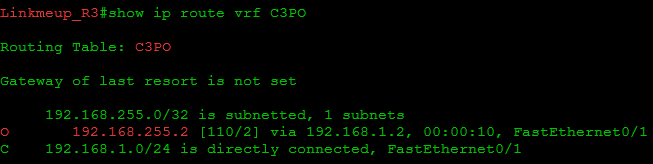
This is how their routing tables on the provider router look like:


C3PO Electronic routes will not fall into the TARS 'Robotics network and vice versa.
Client interfaces here are tied to a specific VRF.
One interface cannot be a member of two VRFs at once or a member of both the VRF and the global routing table.
Using VRF Lite, you can easily forward a VPN between different ends of the network. To do this, you need to configure the same VRF on all intermediate nodes and correctly bind them to the interfaces:

That is, R1 and R2 will communicate with each other through one pair of interfaces in the global routing table, through another pair in VRF TARS 'Robotics and through the third one in VRF C3PO Electronic. Of course, it can be subinterfaces.
Similarly between R2-R3.
Thus, two virtual networks are obtained that do not intersect with each other. Given this fact, in each such network, you need to raise your IGP process to ensure connectivity.
In this case, there will be one process for the physical router, one for TARS 'Robotics, one for C3PO Electric. Accordingly, each of them will be signaled separately from the others through its own interfaces.
If we talk about data transfer, the packet, coming from the node from the TARS's Robotics network, immediately falls into the corresponding VRF, because the input interface R1 is a member of it. According to the FIB of this VRF, it is directed to R2 via the output interface. In the area between R1 and R2 go the most common IP-packets, which do not suspect that they belong to different VPN. The only difference is that they go through different physical interfaces, or carry a different tag in the 802.1q header. R2 accepts this package by an interface that is also a member of TARS's Robotics VRF.
R2 brews the packet in the desired FIB and sends it further, according to IGP. And so on until the very release of the package to the other side of the network.
How does the host determine that the received packet belongs to a particular VPN? Very simple: this interface is tied (“pribinden”) to a specific VRF.
As you have probably noticed, these interfaces are marked with rings of the corresponding color in the illustration.
Let's turn on a little imagination:
If the package passes through the gray ring, itgoes to the gray side and turns gray. Further, it will be checked on the gray routing table.
Similarly, when a packet passes through a gold ring, it is covered with a noble gilding and is checked against a gold routing table.
Similarly, the output interfaces are tied to the VPN, and the corresponding routing tables know what networks they are behind.
Keep in mind that everything we are talking about routing tables applies to the FIB - each VPN has its own FIB.
Between routers packets are not painted . Packages of different VPNs do not mix, because they go either through different physical interfaces, or one by one, but they have different VLAN tags (each VRF has its own output sub-interface).
Here it is a simple and transparent VPN - a private network has been formed for the client.
But this method is convenient, as long as you have 2-3 clients and 2-3 routers. It is completely unscalable, because one new VPN means a new VRF at each node, a new interface, a new pool of link IP addresses, a new IGP / BGP process.
And if the connection points are not 2-3, but 10, and if you need more redundancy, what is it like to raise the IGP with the client and maintain its routes on each of its nodes?
And here we come to MPLS VPN.
MPLS VPN allows you to get rid of these unpleasant steps:
1) Configure the VRF on each node between the connection points
2) Configure separate interfaces for each VRF on each node.
3) Configure separate IGP processes for each VRF on each node.
4) The need to maintain a routing table for each VRF on each node.
How is that?
Consider what is MPLS L3VPN on the example of such a network:

So, these are the three branches of our client TARS 'Robotics: the head office in Moscow and the offices in Novosibirsk and Krasnoyarsk are quite distant to reach their own optical fiber. And we already have channels there.
The central cloud is us - linkmeup - the provider that provides the L3VPN service.
Generally speaking, TARS Robotics as a customer, absolutely no difference how we organize L3VPN - so that we can take their packages by train, if only we could fit in the SLA . But within this article, of course, MPLS works within our network.
First, one should say that in MPLS VPN, a VRF is created only on those routers to which client networks are connected. In our example, this is R1 and R3. Any intermediate nodes do not need to know anything about the VPN.
And between them, you need to somehow provide an isolated transfer of packets of different VPNs.
This is the approach that MPLS VPN offers: switching within the backbone network is carried out, as we described in the previous article , by one MPLS tag, and belonging to a particular VPN is determined by another - an additional tag.
More details:
1) Here the client sends a packet from the network 172.16.0.0/24 to the network 172.16.1.0/24.
2) While it is moving within its branch (client network), it is the most common IP packet, in which Source IP is 172.16.0.2, Destination IP is 172.16.1.2.
3) The branch office network knows that it is possible to get to 172.16.1.0/24 through the provider's network.
Until now, this is the most common package, because the junction is on pure IP with private addresses.
4) Next, R1 (the provider’s router), receives this packet, knows that it belongs to a certain VRF (the interface is tied to VRF TARS), checks the routing table of this VRF — which branch to send the packet to — and encapsulates it into an MPLS packet.
The MPLS label on this packet means that it belongs to a particular VPN. This is called a “Service Tag . ”
5) Next, our router must send a packet to R3 - behind it is the desired office of the client. Naturally, by MPLS. For this, when exiting from R1, the MPLS transport label is hung on it. That is, at this moment on the package two tags.
Promotion of the MPLS package to the cloud occurs exactly as described in the basic MPLS release . In particular, R2 replaces the transport label - SWAP Label.
6) R3 eventually receives the packet, discards the transport label, and by service it understands that it belongs to the VPN TARS 'Robotics.
7) It removes all MPLS headers and sends the packet to the interface as it came to R1 initially.
Theiron-carbon diagram shows how the package is transformed as it travels from PC1 to PC2:
Remember what good MPLS is? The fact that no one cares about what is under the label. Therefore, within the backbone network, it does not matter which address spaces the client has, that is, which IP packet is hidden under the MPLS header.
Since the packet is switched by tags, and not routed by IP addresses - there is no need to maintain a VPN routing table on intermediate nodes.
That is, we get such a convenient MPLS-tunnel, which is signaled, as you will see further, automatically.
So, in the interval between R1 and R3 (that is, in the MPLS cloud), no one has an understanding of what a VPN is - VPN packets move along labels to their destination, and only he has to worry about what to do with them further. This removes the need to raise the VRF on each node and, accordingly, maintain the routing table, FIB, list of interfaces, etc.
Considering that the entire further packet path is defined on the first MPLS router (R1), there is no need for an individual routing protocol in each VPN, although the question remains how to find the output router, which we will answer later.

To better understand how traffic is transmitted, you need to figure out the meaning of the tags in the packet.
If we return to the initial scheme with VRF-Lite , the problem is that the gray color of the IP packet (VPN TARS 'Robotics membership indicator) exists only within the node, and when it is transferred to another, this information is carried in the VLAN tags. And if we refuse subinterfaces on intermediate nodes, porridge will begin. And this must be done for the good of all that is good.
To prevent this from happening in a scenario with MPLS, the Ingress LSR per packet places a special MPLS label - Service - it is a VPN identifier. Egress LSR (the last router is R3) understands from this label that the IP packet belongs to VPN TARS's Robotics and reviews the corresponding FIB.
That is very similar to VLAN, with the difference that only the first router should take care of this.
But based on the service tag, the packet cannot be switched over the MPLS network — if we change it somewhere, then Egress LSR will not be able to recognize which VPN it belongs to.
And here comes to the rescue a stack of tags that we so carefully avoided in the last issue.
The service tag turns out to be internal - the first one in the stack, and the transport one is still hung on top of it.
That is, the MPLS package travels with two labels - top - transport and bottom - service).
Why do you need two tags, why can not you do one service? Let, for example, one label on the Ingress LSR ask one VPN, the other - another. Accordingly, further along the way, they would also switch as usual, and the Egress LSR would know exactly which VRF to transmit the packet to.
Generally speaking, this could be done, and it would work, but then there would be a separate LSP for each VPN on the backbone network. And if, for example, you have a bundle of 20 VPN from R1 to R3, then you would have to create 20 LSPs. And it is more difficult to maintain, it is an overspending of tags, it is an extra load on transit LSR. And, strictly speaking, this is what we're trying to get away from here.
In addition, for different prefixes of the same VPN there may be different labels - this also significantly increases the number of LSPs.
Where is it easier to create one LSP that will tunnel all 20 VPNs at once?
Thus, we need a transport label. She is top on the stack.

It defines the LSP and changes at each node.
It is added (PUSH) Ingress LSR and removed (POP) Egress LSR (or Penultimate LSR in the case of PHP ). On all intermediate nodes, it changes from one to another (SWAP).
LDP and RSVP-TE protocols are involved in the propagation of transport labels. We also talked about this very well in the last article and will not stop now.
In general, the transport tag is of little interest to us, since everything is already clear, except for one detail - FEC.
The FEC is no longer the destination network of the packet (the client’s private address), this is the address of the last LSR in the MPLS network where the client is connected.
This is very important because the LSP is not aware of any VPN there, and therefore does not know anything about their private routes / prefixes. But he knows the addresses of the Loopback interfaces of all LSRs well. So exactly what LSR this client prefix is connected to will be prompted by BGP - this will be the FEC for the transport label.
In our example, R1, based on the destination address of the client packet, must understand that you need to select the LSP that leads to R3.
We will return to this question a little later.

The bottom label on the stack is a service tag. It is the unique identifier for the prefix in a particular VPN.
It is added to Ingress LSR and does not change anywhere else until the Egress LSR itself, which eventually removes it.
The FEC for the Service Tag is the prefix in the VPN, or, roughly speaking, the destination subnet of the original packet. In the example below, the FEC is 192.168.1.0/24 for VRF C3PO and 172.16.1.0/24 for VRF TARS.
That is, the Ingress LSR must know which label is allocated for this VPN. How this happens is the subject of our further research.
This is how the whole packet transfer process in different VPNs looks like:
Note that for two different VPNs, the service tags are different - by them the output router will know which VRF to transmit the packet to.
And the transport in this case is the same for the packets of both VRFs, because they use the same LSP - R1R2R3.
Before we go too far, we need to introduce terminology.
When it comes to MPLS VPN, several new terms appear, which, by the way, are quite obvious:
CE - Customer Edge router - client's border router, which is connected to the provider's network.
PE - Provider Edge router - provider's edge router. Actually, CE is connected to it. VPN is born on PE, and it ends there. This is where the VPN-specific interfaces are located. It is PE that assigns and removes service tags. PEs are Ingress LSR and Egress LSR.
PEs need to know the routing tables of each VPN, because they decide where to send the packet, both within the provider network and in terms of client interfaces.
P - Provider router - a transit router that is not a connection point - VPN packets pass through it without any additional processing, in other words, they are simply switched by the transport label. No need to know the VPN routing tables or service tags. On P, there are no VPN-related interfaces.
In fact, the role of P-PE is individual for VPN. If in one VPN R1 and R3 are PE and R2 is P, then in the other they can change their roles.
For example, in the diagram below, the roles of the blue routers are different for the green client and for the violet:

Label stack - a set of MPLS headers hung on one packet. Each of them performs some of its own role. In our reality, few vendors support more than six tags on the stack.
There will be a number of terms, but it is too early to enter them.
In general, we are done with the way data is transmitted, that is, how Forwading Plane works.
Let's summarize:
The PE router places two tags on client traffic — an internal service that does not change until the very end of the journey and the last PE understands which VRF the package belongs to and the external transport one that transfers the packet through the provider’s network — this label changes to Each P-router is removed on the last PE or the second-to-last P.
Due to the presence of the service tag and the VRF, the traffic of different VPNs is isolated from each other both within routers and in channels.
And actually, now it is possible to formulate a number of troubling questions:
1) How are MPLS tags distributed?
2) How is the routing information distributed for each VPN?
3) How are the routes of different VPNs isolated from each other and not mixed?
These and other questions are answered below.
Answering them, let's talk about how this entire environment is prepared in which data packets will be successfully walked.
So, we have two types of networks and the joints between them:
The boundary of these networks is on PE. That is, one of its half is already client, and the other is provider. It is not in vain that popular wisdom exists: No matter how you tune up PE, it still looks at customers.
MPLS is configured only on trunk interfaces.

I remind you, speech about L3VPN. And here you need to take care of IP connectivity. And now we have a lot of restrictions. We will understand what protocols in which areas will be useful to us.
First , you need to provide basic IP connectivity within the provider’s backbone network. So that all Loopback addresses, link networks, service prefixes, possibly some exits outside are known.
For this, IGP (ISIS, OSPF) is started.
Already on top of the connected network rises MPLS.
So we have ensured the operability of the backbone network .
Secondly , the client in the branches may have not one router, but some networks. These networks also need to be routed inside at least.
Obviously, within its own network, the client is free to distribute route information as he pleases. We as a provider cannot influence this, and we do not care.
This ensures the transfer of routes within customer networks .
Thirdly , the client needs to somehow communicate its routes to the provider. At the junction of CE-PE, the client and the provider already need to agree on which protocol will be used.
Although, the client has hardly any self-written IGP protocol. Surely this is OSPF / ISIS / RIP. Therefore, usually the provider goes forward and chooses the one that is convenient for the client.
Here we must understand that this client interaction protocol works in a VPN and does not overlap with the provider’s IGP. These are different independent processes.
Often, BGP works at this interface, since it allows flexible filtering of prefixes by various attributes.
So the provider receives routes of clients .
Fourth , and this is the most interesting - it remains to transfer the routes of one branch to another through the backbone network. At the same time they should not be lost along the way, not to be confused with strangers, to be delivered safe and sound. Here we will be helped by the extension of the protocol BGP - MBGP - Multiprotocol BGP (Often called MP-BGP). We will talk about it now.
But first look at what works where:

Now we will answer two questions: how are the routes transmitted in the provider network from one PE to another and how is the isolation ensured.
In general, so far, nothing better has been invented for transferring routes to remote sites than BGP: both the flexibility of transferring the routes themselves, and the mass of tools to influence the choice of route, and the policies for receiving and transmitting routes, and the Community, which greatly simplifies group actions. over routes.
If you suddenly forget , here is the usual BGP Update message:

In the NLRI section, it transfers the prefix itself. And in other sections of the mass of its parameters.
To his help and resort to the implementation of MPLS L3VPN. Therefore, his middle name is MPLS BGP VPN.
You remember how this happens? BGP establishes a session with its neighbors via TCP on port 179. This allows you to choose not a directly connected router as neighbors, but those that are in several hopes. This is how IBGP works, where “every with every” connection is assumed within the backbone network.
When several routes leading to the same network arrive at the site, BGP simply selects the best one and installs it into the routing table.
That is, in general, it does not cost us anything to pass the VPN route through the network to the other end.
BGP must take routes from a VRF on one node, deliver them to another and export to the correct VRF there.
The only catch is that BGP is initially focused on working with public addresses that are assumed to be unique throughout the world. But rogue clients usually want to transfer routes to private networks ( RFC1918 ) and, unfortunately , they can easily intersect with both networks of other VPNs and the internal address space of the provider.
That is, if, for example, R3 receives two routes to the network on 10.10.10.10/32 (one from TARS's Robotics, the other from C3PO Electronic), he will choose only one - with the best indicators, as the standard prescribes - he thinks that these are two routes into the same network.

Naturally, this does not suit us. It is necessary that two conditions be fulfilled:
1) Routes of different VPNs were unique and did not mix in transmission between PEs.
2) Routes at the end point must be transferred to the correct VRF.
These problems found an elegant solution. Let's start with item 1 - the uniqueness of the routes.
In our example 10.10.10.10/32 from TARS's Robotics should differ in some way from 10.10.10/32 from C3PO Electronic.
BGP is an incredibly flexible protocol (no wonder that it became the only external gateway protocol). It is easily scaled and with the help of the so-called Address Family, it can transmit routes not only IPv4, but also IPv6 and IPX (but only to whom it is needed). If you want to transfer something new, get your Address Family,
And IETF created a new Address Family. And he gave him the name VPNv4 (or VPN-IPv4).
In order to distinguish between different VPN routes, the usual IPv4 prefix is supplemented with a special prefix 8 bytes long - RD - Route Distinguisher .
Then the route from C3PO will look like this: 64500: 100 : 10.10.10.10/32, and from TARS like this: 64500: 200 : 10.10.10 / 32 . And now these are completely different things that the BGP process can distinguish from each other.
Let's figure out what RD is and how to define it.
There are 3 types of RD:

Inspired .
The first part is the type itself (0, 1 or 2);
The second part of- Administrative field (Administrator field) is always a public parameter - public IP-address or public AS number. It is necessary so that your RDs are unique not only within the network, but also within the planet.
That is, in the Administrative part, the IP address 172.16.127.2 or AS 65001 should not appear by chance. This can be useful if the VPN needs to be transferred to the network of another provider (and this is also possible in our insane time, and it even carries the name Inter -AS VPN).
The third part - Assigned Number - this is what you assign. This part allows the RD to be unique within your network and, in fact, define a VPN.
As you can see, RD is unique within the planet.
Here are two examples of converting a regular IPv4 prefix 10.10.10.10/32 to VPNv4:
or
Which one you choose does not matter, even if within the network you use both approaches at the same time. Even for one VRF on different routers. The main task of RD is to separate the prefixes.
That is, if in a very simple language: it doesn't matter at all what you configure, the main thing is that you are sure that BGP will never confuse the routes of different VPNs.
Although the systematization still no one interfered.
Typically, type 0 is used, the Administrative field is the AS number of the provider, and you select the Dedicated number yourself. When configuring RD, the first "0:" or "1:" (type RD) are reduced and it turns out like this: 64500: 100 and 100.0.0.1:100 .
Cisco allows you to use types 0 and 1.
Yes, RD will have to be configured manually and you should follow its uniqueness yourself. But it will not work out differently here - the routers themselves do not know how to track whether there is already such an RD on other nodes or not. And if there is, then is this the same VPN?
And what do we get?
1) Comes from CE announcement of the new network. Let it be 10.10.10.10/32, as we agreed. PE adds this route to the specific VRF routing table. Notice that the normal IPv4 route is stored in the routing table — no VPNv4. And this is not necessary: VRFs are isolated from each other, as we have said before - this is a separate, albeit virtual, router.
2) BGP noticed that a new prefix appeared in the VPN. From the VRF configuration, it sees which RD should be used. Compiles from the RD and the new IPv4 prefix, a VPNv4 prefix. It turns out like this:
C3PO: 64500: 100: 10.10.10.10/32
or so:
TARS: 64500: 200: 10.10.10.10/32
3) When creating BGP Update, the router inserts the received VPNv4 prefix, the address of Next Hop and other BGP attributes there. But among other things, he adds information about the label in the NLRI field. This label is tied to the route, or more precisely, the VPNv4 prefix is an FEC, and in the NLRI a bunch of the given FEC and the label is transmitted.
In English, this is called Labeled Route - in Russian, perhaps, a route marked with a label . So this PE notifies its neighbors that if they received an IP packet from the CE into this network, they need to assign such a service tag.

Also note the Next Hop address is Loopback PE. And this is very correct - Ingress PE should know to which Egress PE the incoming data packet should be sent, that is, to know its Loopback, and then at least the flood.
4) Next, BGP Update is transmitted to all neighbors configured in the VPNv4 family section.
5) Remote PE receives this Update, sees in the NLRI that it is not a normal IPv4 route, but VPNv4. Remember, yes: if two routes come to the same network from different clients - they will not be confused, because they have different RDs. Further, Egress PE determines which VRF this route should be exported to and actually does it. So the route appears in the routing table and FIB of the desired VRF, and from there it goes to the client’s network.
Now, when PE receives a data packet from CE that follows the 10.10.10.10/32 network, it finds the service tag (22) and Next-Hop (1.1.1.1) in the FIB of this VPN. Encapsulates IP in MPLS, further searches in the already global FIB transport label for Next Hop.
The transport label itself is still delivered by the LDP or RSVP-TE protocols, and the service label is delivered by MBGP.
Compare the NLRI field in normal BGP and in MP-BGP.

It’s not for nothing that in the fifth paragraph I highlighted the phrase “determines which VRF this route should be exported” in italics. Behind this simplicity is another thing - RT - Route Target .
The fact is that the only role of RD is to diversify the life of BGP, that is, to make routes unique. Despite the fact that it is configured for VRF, it is not some unique identifier of it and at all points of connection this value may even be different. Therefore, PE cannot determine in which VRF a route is thrust based on RD.
Yes, and it would not be entirely in the tradition of BGP - to parse the transmitted address, analyze it before announcing somewhere. For these purposes we have policies.
That is, in a classic BGP, you would have to hang policies for exporting routes to the VRF for each one separately. And we would manually filter out where you need to attach each route.
One step towards simplification is to use the community. When sending a route from one PE to another, you can set up a certain community - a different one for each VRF, and on the remote one for this community you can set up export to the corresponding VRF. It already looks comfortable and convincing.
MBGP went a little further - the idea of the community was developed to the concept of Route Target. In fact, this is the same community - RT is even transmitted in the Extended Community attribute, only all policies work automatically.
The RT format is exactly the same as the ordinary Extended Community. For example:
64500: 100
That is, it looks like the first type of RD. This is partly why RD and RT are so often confused.
On one side of the VRF, RT is configured to export the route - the RT with which it will travel to the remote PE. On the other, the exact same RT value is set for import. And vice versa.
Usually, if the task is to simply organize a VPN service for one client, then RT for export and import coincide at all connection points.
Returning to our example:
R1 sends the R3 route to the network on 10.10.10.10/32 (TARS 'Robotics), specifies the label and all other parameters, and among other things, it writes RT to the Extended Community attribute on the route export configured for this VRF: 64500: 200.
R3 receives this announcement, checks the community, sees 64500: 200, and from the configuration it knows that routes with this RT need to be imported into VRF TARS.

Handsomely? Elegantly? But that is not all. The flexibility of BGP is here again. With the help of the RT mechanism, you can import routes as you like, both within the same VPN and between different VPNs.
Here are two scenarios:
It remains to see the process of transferring the route from and to:

Traditionally, in practice, we repeat everything that was still in theory.
So let's go from simple to complex. Let's start with the situation when one client has two connections to one router:

First, let's try to set everything up the way we did before:
Linkmeup:
C3PO_1:
C3PO_2:
Ping between branches appears - they see each other.

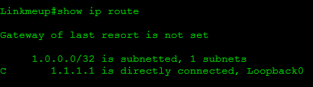
But they also see, for example, the address of Loopback R1:

Accordingly, they see the entire network of the provider and will see the networks of other customers.
Therefore, we configure VRF:
To place clients in this VRF, you need to bind their interfaces to the VRF:
Please note that after executing the ip vrf forwarding C3PO command, IOS removed the IP addresses from the interfaces, now they need to be reconfigured. This happened in order to remove the specified subnets from the global routing table.
After reconfiguring the address, these subnets will appear in the VRF routing table.

Check ping again:

But before the internal address of the provider will not be:

Similar settings need to be made for the TARS client:
Well, fine. VRF TARS and C3PO are completely isolated from the provider’s network and from each other:


Now we stretch the fun to the network linkmeup:

The first configuration step is to create a VRF on each node from R1 to R3:
* It should be understood that VRF is a strictly local concept for a node. It is possible to set different VRF names on different routers.
The second step is to create a chain of link networks between all nodes and bind each pair of interfaces to the desired VRF .
Linkmeup_R1 :
The third is to raise the IGP in the VRF .
Linkmeup_R1 :
Actually everything. Now each network knows its routes:


In principle, on the basis of a single physical network, we have created three completely independent virtual networks, within which you can do almost anything you want - at least to raise your MPLS.
But, as it was said before, this is a very inert solution, so we turn to MPLS BGP VPN.
I propose this time not to take a ready-made network, where everything is already pre-configured. Now it will be more interesting to go this way from scratch, even if only by milestones, without going into details.
So, we are torturing the same network, but simplify it by removing one branch:

Let's start with one client and two connection points.
Client routers have a very simple configuration:
C3PO_1:
C3PO_2:
Link addresses with the provider and the Loopback interface are configured on the client nodes (as before, we use this interface to simulate the network so as not to produce routers). That is, if at C3PO_2 we see the network 192.168.255.1/32, this means that we would see the entire network completely.
OSPF is used as the local dynamic routing protocol. Actually, it is he who will let the interested party know the address of the Loopback interface.
As for the network provider.
First, we will give a brief setup procedure, and then we will show with an example.
1) Configure IP-addresses: link and loopback. We do not touch the client yet.
Linkmeup_R1 :
Linkmeup_R2 :
Linkmeup_R3 :
Initial configuration file.
2) Now we are raising ISIS as IGP - it will link the entire network linkmeup, distributing route information about link and Loopback addresses.
Linkmeup_R1 :
Linkmeup_R2 :
Linkmeup_R3 :
At this step, we got a global routing table - the necessary platform for the next step.

3) Turn on MPLS and LDP:
Linkmeup_R1 :
Linkmeup_R2 :
Linkmeup_R3 :
In this step, we have built LSPs between all LSR pairs:

* An example of tag allocation on Linkmeup_R1 .
This is the basis for VPN. These LSPs are a set of transport labels.
4) Create a VRF on two nodes: Linkmeup_R1 and Linkmeup_R3 .
Linkmeup_R1 :
Linkmeup_R3 :
This allows us to isolate all the data of one client from others and from the network of the provider.
Here we indicate RD and RT. Since we have a simple task - to connect all the branches of C3PO Electronic, we will make the RD and RT the same. Moreover, RT on Import and RT on Export will also be the same. Since this is a common practice, there is even a special directive - both - then both RTs are created immediately the same.
In the 8th release, we chose the AS number for the network linkmeup - 64,500. It is used as an administrative field.
The selected number is chosen arbitrarily, but is tracked so that there is no coincidence with another, already used.
5) Bind the interfaces to the VRF and point them to the IP addresses.
Linkmeup_R1 :
Linkmeup_R3 :
In the routing tables of VRF C3PO, configured networks should appear as Directly connected.


6) It is necessary to raise the routing protocol with the client. In our case, it will be OSPF, although it could be ISIS or EBGP with equal success. This process should not intersect with the global routing table, so we put it in the VRF:
Linkmeup_R1 :
Linkmeup_R3 :
Given that the OSPF client is already configured, we should see the addresses of the Loopback interfaces in the routing table.

As you can see, Linkmeup_R1 sees 192.168.255.1, but does not see the remote Loopback - 192.168.255.2. Similarly, Linkmeup_R3 sees only routes for its part. This is because the client’s routes are not transmitted through the provider’s network yet.
7) So it's MBGP time.
Remember, we talked about BGP Free Core in the last issue? We can use this technique here. Without need of BGP on Linkmeup_R2 , we will not raise it there.
The first part is the basic setting of iBGP neighbors.
Linkmeup_R1 :
Linkmeup_R3 :
The second part — setting the Address Family VPNv4 — is what allows Linkmeup_R1 on Linkmeup_R3 to transfer client routes. Notice that we activate the transfer community, because this attribute is used by RT.
Linkmeup_R1 :
Linkmeup_R3 :
The third part is the Address Family for this particular VRF. It works with regular IPv4 prefixes, but from VRF C3PO Electronic. It is needed in order to transfer routes between MBGP and OSPF.
Linkmeup_R1 :
Linkmeup_R3 :
As you can see, route import from OSPF process number 2 is configured here.
Accordingly, you need to configure and import routes to OSPF from BGP:
Linkmeup_R1 :
Linkmeup_R3 :
And now everything is wrapped, twisted.
Routes on PE:


Routes on CE:

Ping between client networks:

Attempting to ping provider network:

That's nice.
Connecting a client via BGP
Now connect the TAR'S Robotics client. Routes between CE and PE will be sent over BGP or, in other words, we are raising EBGP with a client router.
Steps 4 and 5 will not be different. We present the configuration of only one side:
6) On CE, EBGP is configured in the most usual way.
TARS_1:
Here it is stated that TARS 'Robotics will announce its network 172.16.255.1/32.
OSPF may still be needed, but it will already be used for routing within this branch and only.
On PE, everything is the same, only there will not be a new OSPF process (because now the client has EBGP, instead of OSPF) and the address family is changing ipv4 vrf TARS:
Linkmeup_R1 :
Linkmeup_R1 is now a BGP neighbor TARS_1 :

It will receive client networks with Update messages from CE.
7) Everything related to MBGP is the same. From the fact that we changed the client interaction protocol, nothing will turn over in it.
That is, now everything should work (if, of course, the second side is configured): The


complete configuration of all nodes with or without comments .
What have we done?
Let's now trace the distribution of tags.
That's what gave Linkmeup_R1 node Linkmeup_R3 .

You see mark 22 here for FEC 192.168.255.1 and Next Hop address 1.1.1.1.
How does the router understand it?
In TM VRF C3PO, it enters information on which Next Hop:

Recursively calculate how 1.1.1.1 is available: The

service label can be seen in the BGP table for VRF C3PO:

By the way, Next Hop is also visible here.
Transport label for FEC 1.1.1.1:

But, as usual, the FIB contains all the relevant information without multiple appeals to the TM: the

FIB tells us: pack a package with DIP192.168.255.1 to the stack of tags {17, 22} and send it towards 10.0.23.2 to the interface FE0 / 0.
Everything here is extremely clear and deterministic.
Let's summarize the L3VPN configuration steps from scratch in the correct order from general to specific.
These were necessary and sufficient actions to configure the basic L3VPN.
Well, the last scenario in the framework of practice is
Somewhere there - far above - we assumed the existence of a certain third client - R2D2, which has some views on C3PO - and in particular they have to exchange routes, while being in different VPNs.
Here is the scheme: Here we will work with RT - we will make the routes from VPN C3PO be transferred to R2D2 by BGP protocol. Well, and back - where without it? R2D2 router configuration :
Configuring VRF on Linkmeup_R3 :
Actually, there is nothing new here, except for setting the route-target in the VRF.
As you can see, besides the usual command “route-target both 64500: 300” we also gave “route-target import 64500: 100”. It means that you need to import routes from RT 645500: 100, that is, from VPN C3PO to VRF, as we wanted.
Immediately after this, the routes appear on R2D2 :

After that, the ping successfully passes to 192.168.255.2:

But, if you run the ping to the address 192.168.255.1, it will not pass. Why?

For interest, you can add Loopback 1 with address 10.20.22.22/32 on TARS_2 - the same as Loopback 0 R2D2 and see what happens.
Complete configuration of all nodes for a VPN VPN interaction scenario.
It may be that the provider in the same VPN also provides access to the Internet. It is in the VPN, not a separate cable, not a separate VLAN, but access to the Internet through the same connection, through the same addresses. This may also be the caprice of the customer.
The topic is interesting, but big, so I will reveal it a little later in a separate micro issue.
About a year ago I had a small article with tricky questions.
Among them was one very relevant for us.
It's time to make it out better.
If suddenly, you didn’t know how regular tracing works, then I’ll briefly tellyou shame .
You send packets to the recipient with a gradually increasing TTL value. This is usually UDP, but it can be ICMP and even TCP.
First it is 1. The packet reaches the directly connected router, it reduces the TTL, sees that it is now zero, forms the message “time exceeded in transit” and sends it back to you. So at the address of the sender you know the first hop.
Then it is 2. The packet reaches the second router. The same thing happens, so you learned the next hop.
...
Finally, the TTL reaches N, the destination node receives the packet, sees that it is to it, forms the answer (in accordance with the protocol), by which you understand that everything is over and ends to the console.
In addition, you can add that at each iteration you send not one, but several packets (usually three).
What is special about tracing via L3VPN?
As long as the packet is switched by labels, the values of any fields of any headers deeper than MPLS have no meaning. Including TTL. Routers are oriented on the TTL in the MPLS header.
And when PE receives a packet from CE, there are two options:
In the first scenario, you can see each router on its way to the destination. The result of the trace will be as follows: The

mechanics are as follows:
And what if I have a logical desire for customers not to see the topology of my network with their own traces? We must ban, you say. As the father of a two-year-old daughter, I tell you: no need to ban. It is possible and necessary to act smarter - I simply will not reduce the TTL MPLS to zero inside my network.
The second scenario is used for this - set the MPLS TTL to 255. In this case, when tracing from TARS_1, you will see the following path: R1R3TARS_2.

And no matter how many transit P routers, TTL = 3 will always suffice when tracing from TARS_1 to TARS_2.
The default behavior is different for vendors.
Tsisk believes that the engineer knows what he is doing and what he faces every action, so he chooses the first path, and, for example, Huawei prefers to play it safe - it’s better to ban it first, so that it does not work out, and then the engineer will allow if necessary.
In any case, the mode can always be changed - in our case, in the global configuration mode, you need to give the command “no mpls ip propagate-ttl” for this.
A wonderful fifty- three-page tracing document at nano.org .
By the way, for MPLS there are special utilities of ping and tracing .
Wonderful chapter Questions and Answers. I really like it, because here you can shove everything that was not enough space in the main article.
Q1: Can we say that P is Intermediate LSR, and PE is LER?
Q2: Why is MBGP a MultiProtocol BGP, and not, for example, MPLS BGP? What is multiprotocol in it?
Q3: Where are the routes, RDs and their attributes in MBGP transmitted?
Q4: So what's the difference between RD and RT? Why is not enough just one of them? And I understood correctly: RD is not a VPN identifier, like RT?
Q5: Young, man, we are a large operator, we are doing serious things - we are building Adnvanced LTE, while we support 2G, we do not have clients who want a VPN, your giant article is useless for us.
B6: I will not understand: how Egress PE, having received a packet with one label, that is, if PHP occurred, determines that this VPN label is not a transport tag, and, accordingly, that the label needs to be sent to the VRF, and not to be connected where next?
I keep on saying that all terms and abbreviations used in the article can be found in the lookmeup glossary . Okay, I dissemble: not all, but only the majority
Beloved by me Jeff Doyle: VPN in two parts: Part I , Part II .
Jeremy Stretch: Route Distinguishers and Route Targets writes about the differences between RD and RT .
As you can see, creating L3VPN is a lot of manual work. And if necessary, to organize the interaction between the VPN, you have to configure not only one Internet gateway, even in the most correct and beautiful way, but also client PE.
But all this work is necessary, there is no redundancy. For contrast, remember what setup you get up to, VPN with GRE or VRF-Lite.
And note that the P- Linkmeup_R2 router has remained completely unchanged during all stages of configuration since the initial inclusion of MPLS on it. Isn't that pretty ?!
This is not to say that we embraced the whole L3VPN with this small article, in particular, such interesting things as Inter-AS VPN, of which 3 types, and CSC (Carrier Support Carrier) remained outside the general picture. But I hope to write a separate article specifically on these two mechanisms.
L3VPN is a mature, well thought out and standardized thing. All manufacturers, it works plus / minus the same.
But ahead there is another article about L2VPN, which will include AToM, VLL, PWE3 and VPLS. In it we learn the role played by Cisco and Juniper in the development of this direction, what joy in our lives bring services such as CES or EoMPLS. Be patient - this year I will try to increase the pace, gain momentum, unwind and increase efficiency.
Project illustrator - Anastasia Metzler .
For assistance in preparing the article, thank you JDima .
Stay in touch.
But so far, only real-life application of it is drawn. And that's bad.
This article will begin to correct the situation. In general, the reader is waiting for a series of three articles: L3VPN, L2VPN, Traffic Engineering, where we will try to fully tell why MPLS is needed in practice.
')
So, linkmeup is no longer an outsourcing of support for a large but single company, we are a provider. You can even say the federal provider, because our optics leads to all parts of the country. And our numerous clients want not only high-speed Internet access, they want VPN.
Today we will understand what will have to be done on our network (on which MPLS is already set up in the meantime) in order to satisfy these rampant appetites.
Issue content
- VRF, VPN Instance, Routing Instance
- >>> VRF-Lite
- MPLS L3VPN
- >>> Data Plane or transfer of user data
- >>>>>> The Role of MPLS Tags
- >>>>>>>>> Transport Tag
- >>>>>>>>> Service Tag
- >>> Terminology
- >>> Control Plane or transfer of service (routing) information
- >>>>>> Routing Protocols
- >>>>>>>>> MBGP
- >>>>>>>>>>>> Route Distinguisher
- >>>>>>>>>>>> Route Target
- Practice
- >>> VRF-Lite
- >>> MPLS L3VPN
- >>>>>> VPN Interaction
- Tracing MPLS L3VPN
- Q & A
- useful links
Traditional video:
How to organize the interaction of two remote sites on the Internet? Very simple, if they have public addresses - the IP for this was invented. They can communicate directly. In any case, to connect two points on the Internet, you need two public addresses - one on each side. And if we have private addresses (10/8, 172.16 / 20, 192.168 / 16)?
Then they will "pull on" on the one hand, and then "spread out" on the other. And NAT is a thing, I tell you, oh, how nasty.
Therefore, there is a VPN. Virtual Private Network is a set of technologies and protocols that allows you to connect something to your private network through someone else's network, in particular, through the Internet.
For example, the Tomsk branch of the company linkmeup can be connected to the head office in Moscow using VPN over the Internet, as we did in the VPN issue .
That is, you will see other branches through VPN as if they were in the next room and you are connected to them through a cord, switch or router. Accordingly, the nodes can communicate at their private addresses, rather than publicly.
In this case, your personal data with private addresses are packaged in packages with public addresses and how in the tunnel they fly over the Internet.
This is called client VPN , because the client is concerned about its configuration and elevation. His only agent is the Internet.
We analyzed it in the 7th edition and there is a huge article about it on the linkmeup blog by our reader, Vadim Semyonov.
Another possible option is provider VPN . In this case, the provider provides the client with several connection points, and within its network builds channels between them.
The client is then only required to pay the provider this channel.
Provider VPN, unlike client, allows to provide a certain quality of services. Usually, when concluding an agreement, an SLA is signed, where the delay level, jitter, percentage of packet loss, the maximum period of unavailability of services, etc. are specified. And if in the client VPN you can only hope that everything is calm on the Internet now, and your data will reach in perfect order, then in the provider, you have someone to ask.
This time we will focus on the provider VPN.
This is about Layer 3 VPN - L3VPN, when we need to route network traffic. L2VPN is the topic of the next issue.
VRF, VPN-Instance, Routing-instance
When it comes to VPN, the question of traffic isolation arises. No one else should receive it, and your private addresses should not appear where they are not supposed to - that is, on the Internet, on our provider's network and on other customers' VPNs.
When you set up a GRE tunnel via the Internet (or OpenVPN, to your taste), your data is automatically segregated - no one can see your private addresses on the Internet, and traffic will not fall into the wrong hands (unless you raise the issue of a targeted attack).
That is, there is a tunnel between two public addresses, which is in no way connected with your provider or with other transit tunnels. Two different VPNs — two completely different tunnels — and only your traffic flows through your tunnel.
Quite different is the question in the provider VPN - the same backbone network must transfer data from hundreds of clients. How to be here?
No, you can, of course, and here GRE, OpenVPN, L2TP and others like them, but then all that the operating engineers will do is tune the tunnels and shovel millions of configuration lines.
But the problem is deeper - the question of organizing such a universal channel for all is secondary: the main thing now is how to isolate two clients connected to the same router? If, for example, both use a 10.0.0.0/8 network, how to prevent traffic from being routed between them?
Here we come to the concept of VRF - Virtual Routing and Forwarding instance. The terminology is not settled here: in Cisco - this is VRF, in Huawei - VPN instance, in Juniper - Routing Instance. All names have the right to life, but the essence is the same - the virtual router. This is something like a virtual machine in some VirtualBox - there are many virtual servers on one physical server, and here there are many virtual routers on one physical router.
Each such virtual marsurcher is essentially a separate VPN. Their routing tables, FIB, interface list and other parameters do not overlap - they are strictly individual and isolated. Exactly the same way they are separated from the physical router itself. But as in the case of virtual servers, communication is possible between them.
VRF - it is strictly local to the router - there is no VRF outside of it. Accordingly, the VRF on one router is in no way associated with the VRF on the other.
Since we are reviewing all the examples on Cisco equipment, we will stick to their terminology.
VRF Lite
This is the name of creating a provider VPN without MPLS.
For example, this is how you can configure VPN within the same router:
Here we have two clients - TAR's Robotics and C3PO Electronic.
The FE0 / 0 and FE0 / 1 interfaces belong to VPN C3PO Electronic, the FE1 / 0 and FE1 / 1 interfaces are VPN TAR's Robotics. Inside one VPN, the nodes communicate without problems, among themselves - nothing at all.
This is how their routing tables on the provider router look like:
C3PO Electronic routes will not fall into the TARS 'Robotics network and vice versa.
Client interfaces here are tied to a specific VRF.
One interface cannot be a member of two VRFs at once or a member of both the VRF and the global routing table.
Using VRF Lite, you can easily forward a VPN between different ends of the network. To do this, you need to configure the same VRF on all intermediate nodes and correctly bind them to the interfaces:
That is, R1 and R2 will communicate with each other through one pair of interfaces in the global routing table, through another pair in VRF TARS 'Robotics and through the third one in VRF C3PO Electronic. Of course, it can be subinterfaces.
Similarly between R2-R3.
Thus, two virtual networks are obtained that do not intersect with each other. Given this fact, in each such network, you need to raise your IGP process to ensure connectivity.
In this case, there will be one process for the physical router, one for TARS 'Robotics, one for C3PO Electric. Accordingly, each of them will be signaled separately from the others through its own interfaces.
If we talk about data transfer, the packet, coming from the node from the TARS's Robotics network, immediately falls into the corresponding VRF, because the input interface R1 is a member of it. According to the FIB of this VRF, it is directed to R2 via the output interface. In the area between R1 and R2 go the most common IP-packets, which do not suspect that they belong to different VPN. The only difference is that they go through different physical interfaces, or carry a different tag in the 802.1q header. R2 accepts this package by an interface that is also a member of TARS's Robotics VRF.
R2 brews the packet in the desired FIB and sends it further, according to IGP. And so on until the very release of the package to the other side of the network.
How does the host determine that the received packet belongs to a particular VPN? Very simple: this interface is tied (“pribinden”) to a specific VRF.
As you have probably noticed, these interfaces are marked with rings of the corresponding color in the illustration.
Let's turn on a little imagination:
If the package passes through the gray ring, it
Similarly, when a packet passes through a gold ring, it is covered with a noble gilding and is checked against a gold routing table.
Similarly, the output interfaces are tied to the VPN, and the corresponding routing tables know what networks they are behind.
Keep in mind that everything we are talking about routing tables applies to the FIB - each VPN has its own FIB.
Between routers packets are not painted . Packages of different VPNs do not mix, because they go either through different physical interfaces, or one by one, but they have different VLAN tags (each VRF has its own output sub-interface).
Here it is a simple and transparent VPN - a private network has been formed for the client.
But this method is convenient, as long as you have 2-3 clients and 2-3 routers. It is completely unscalable, because one new VPN means a new VRF at each node, a new interface, a new pool of link IP addresses, a new IGP / BGP process.
And if the connection points are not 2-3, but 10, and if you need more redundancy, what is it like to raise the IGP with the client and maintain its routes on each of its nodes?
And here we come to MPLS VPN.
MPLS L3VPN
MPLS VPN allows you to get rid of these unpleasant steps:
1) Configure the VRF on each node between the connection points
2) Configure separate interfaces for each VRF on each node.
3) Configure separate IGP processes for each VRF on each node.
4) The need to maintain a routing table for each VRF on each node.
How is that?
Consider what is MPLS L3VPN on the example of such a network:
So, these are the three branches of our client TARS 'Robotics: the head office in Moscow and the offices in Novosibirsk and Krasnoyarsk are quite distant to reach their own optical fiber. And we already have channels there.
The central cloud is us - linkmeup - the provider that provides the L3VPN service.
Generally speaking, TARS Robotics as a customer, absolutely no difference how we organize L3VPN - so that we can take their packages by train, if only we could fit in the SLA . But within this article, of course, MPLS works within our network.
Data Plane or transfer of user data
First, one should say that in MPLS VPN, a VRF is created only on those routers to which client networks are connected. In our example, this is R1 and R3. Any intermediate nodes do not need to know anything about the VPN.
And between them, you need to somehow provide an isolated transfer of packets of different VPNs.
This is the approach that MPLS VPN offers: switching within the backbone network is carried out, as we described in the previous article , by one MPLS tag, and belonging to a particular VPN is determined by another - an additional tag.
More details:
1) Here the client sends a packet from the network 172.16.0.0/24 to the network 172.16.1.0/24.
2) While it is moving within its branch (client network), it is the most common IP packet, in which Source IP is 172.16.0.2, Destination IP is 172.16.1.2.
3) The branch office network knows that it is possible to get to 172.16.1.0/24 through the provider's network.
Until now, this is the most common package, because the junction is on pure IP with private addresses.
4) Next, R1 (the provider’s router), receives this packet, knows that it belongs to a certain VRF (the interface is tied to VRF TARS), checks the routing table of this VRF — which branch to send the packet to — and encapsulates it into an MPLS packet.
The MPLS label on this packet means that it belongs to a particular VPN. This is called a “Service Tag . ”
5) Next, our router must send a packet to R3 - behind it is the desired office of the client. Naturally, by MPLS. For this, when exiting from R1, the MPLS transport label is hung on it. That is, at this moment on the package two tags.
Promotion of the MPLS package to the cloud occurs exactly as described in the basic MPLS release . In particular, R2 replaces the transport label - SWAP Label.
6) R3 eventually receives the packet, discards the transport label, and by service it understands that it belongs to the VPN TARS 'Robotics.
7) It removes all MPLS headers and sends the packet to the interface as it came to R1 initially.
The
Remember what good MPLS is? The fact that no one cares about what is under the label. Therefore, within the backbone network, it does not matter which address spaces the client has, that is, which IP packet is hidden under the MPLS header.
Since the packet is switched by tags, and not routed by IP addresses - there is no need to maintain a VPN routing table on intermediate nodes.
That is, we get such a convenient MPLS-tunnel, which is signaled, as you will see further, automatically.
So, in the interval between R1 and R3 (that is, in the MPLS cloud), no one has an understanding of what a VPN is - VPN packets move along labels to their destination, and only he has to worry about what to do with them further. This removes the need to raise the VRF on each node and, accordingly, maintain the routing table, FIB, list of interfaces, etc.
Considering that the entire further packet path is defined on the first MPLS router (R1), there is no need for an individual routing protocol in each VPN, although the question remains how to find the output router, which we will answer later.
To better understand how traffic is transmitted, you need to figure out the meaning of the tags in the packet.
The role of MPLS tags
If we return to the initial scheme with VRF-Lite , the problem is that the gray color of the IP packet (VPN TARS 'Robotics membership indicator) exists only within the node, and when it is transferred to another, this information is carried in the VLAN tags. And if we refuse subinterfaces on intermediate nodes, porridge will begin. And this must be done for the good of all that is good.
To prevent this from happening in a scenario with MPLS, the Ingress LSR per packet places a special MPLS label - Service - it is a VPN identifier. Egress LSR (the last router is R3) understands from this label that the IP packet belongs to VPN TARS's Robotics and reviews the corresponding FIB.
That is very similar to VLAN, with the difference that only the first router should take care of this.
But based on the service tag, the packet cannot be switched over the MPLS network — if we change it somewhere, then Egress LSR will not be able to recognize which VPN it belongs to.
And here comes to the rescue a stack of tags that we so carefully avoided in the last issue.
The service tag turns out to be internal - the first one in the stack, and the transport one is still hung on top of it.
That is, the MPLS package travels with two labels - top - transport and bottom - service).
Why do you need two tags, why can not you do one service? Let, for example, one label on the Ingress LSR ask one VPN, the other - another. Accordingly, further along the way, they would also switch as usual, and the Egress LSR would know exactly which VRF to transmit the packet to.
Generally speaking, this could be done, and it would work, but then there would be a separate LSP for each VPN on the backbone network. And if, for example, you have a bundle of 20 VPN from R1 to R3, then you would have to create 20 LSPs. And it is more difficult to maintain, it is an overspending of tags, it is an extra load on transit LSR. And, strictly speaking, this is what we're trying to get away from here.
In addition, for different prefixes of the same VPN there may be different labels - this also significantly increases the number of LSPs.
Where is it easier to create one LSP that will tunnel all 20 VPNs at once?
Transport tag
Thus, we need a transport label. She is top on the stack.
It defines the LSP and changes at each node.
It is added (PUSH) Ingress LSR and removed (POP) Egress LSR (or Penultimate LSR in the case of PHP ). On all intermediate nodes, it changes from one to another (SWAP).
LDP and RSVP-TE protocols are involved in the propagation of transport labels. We also talked about this very well in the last article and will not stop now.
In general, the transport tag is of little interest to us, since everything is already clear, except for one detail - FEC.
The FEC is no longer the destination network of the packet (the client’s private address), this is the address of the last LSR in the MPLS network where the client is connected.
This is very important because the LSP is not aware of any VPN there, and therefore does not know anything about their private routes / prefixes. But he knows the addresses of the Loopback interfaces of all LSRs well. So exactly what LSR this client prefix is connected to will be prompted by BGP - this will be the FEC for the transport label.
In our example, R1, based on the destination address of the client packet, must understand that you need to select the LSP that leads to R3.
We will return to this question a little later.
Service Tag
The bottom label on the stack is a service tag. It is the unique identifier for the prefix in a particular VPN.
It is added to Ingress LSR and does not change anywhere else until the Egress LSR itself, which eventually removes it.
The FEC for the Service Tag is the prefix in the VPN, or, roughly speaking, the destination subnet of the original packet. In the example below, the FEC is 192.168.1.0/24 for VRF C3PO and 172.16.1.0/24 for VRF TARS.
That is, the Ingress LSR must know which label is allocated for this VPN. How this happens is the subject of our further research.
This is how the whole packet transfer process in different VPNs looks like:
Note that for two different VPNs, the service tags are different - by them the output router will know which VRF to transmit the packet to.
And the transport in this case is the same for the packets of both VRFs, because they use the same LSP - R1R2R3.
Terminology
Before we go too far, we need to introduce terminology.
When it comes to MPLS VPN, several new terms appear, which, by the way, are quite obvious:
CE - Customer Edge router - client's border router, which is connected to the provider's network.
PE - Provider Edge router - provider's edge router. Actually, CE is connected to it. VPN is born on PE, and it ends there. This is where the VPN-specific interfaces are located. It is PE that assigns and removes service tags. PEs are Ingress LSR and Egress LSR.
PEs need to know the routing tables of each VPN, because they decide where to send the packet, both within the provider network and in terms of client interfaces.
P - Provider router - a transit router that is not a connection point - VPN packets pass through it without any additional processing, in other words, they are simply switched by the transport label. No need to know the VPN routing tables or service tags. On P, there are no VPN-related interfaces.
In fact, the role of P-PE is individual for VPN. If in one VPN R1 and R3 are PE and R2 is P, then in the other they can change their roles.
For example, in the diagram below, the roles of the blue routers are different for the green client and for the violet:
Label stack - a set of MPLS headers hung on one packet. Each of them performs some of its own role. In our reality, few vendors support more than six tags on the stack.
There will be a number of terms, but it is too early to enter them.
In general, we are done with the way data is transmitted, that is, how Forwading Plane works.
Let's summarize:
The PE router places two tags on client traffic — an internal service that does not change until the very end of the journey and the last PE understands which VRF the package belongs to and the external transport one that transfers the packet through the provider’s network — this label changes to Each P-router is removed on the last PE or the second-to-last P.
Due to the presence of the service tag and the VRF, the traffic of different VPNs is isolated from each other both within routers and in channels.
And actually, now it is possible to formulate a number of troubling questions:
1) How are MPLS tags distributed?
2) How is the routing information distributed for each VPN?
3) How are the routes of different VPNs isolated from each other and not mixed?
These and other questions are answered below.
Control Plane or transfer of service (routing) information
Answering them, let's talk about how this entire environment is prepared in which data packets will be successfully walked.
Routing protocols
So, we have two types of networks and the joints between them:
- Client IP network;
- Provider's backbone network with MPLS running on it.
The boundary of these networks is on PE. That is, one of its half is already client, and the other is provider. It is not in vain that popular wisdom exists: No matter how you tune up PE, it still looks at customers.
MPLS is configured only on trunk interfaces.
I remind you, speech about L3VPN. And here you need to take care of IP connectivity. And now we have a lot of restrictions. We will understand what protocols in which areas will be useful to us.
First , you need to provide basic IP connectivity within the provider’s backbone network. So that all Loopback addresses, link networks, service prefixes, possibly some exits outside are known.
For this, IGP (ISIS, OSPF) is started.
Already on top of the connected network rises MPLS.
So we have ensured the operability of the backbone network .
Secondly , the client in the branches may have not one router, but some networks. These networks also need to be routed inside at least.
Obviously, within its own network, the client is free to distribute route information as he pleases. We as a provider cannot influence this, and we do not care.
This ensures the transfer of routes within customer networks .
Thirdly , the client needs to somehow communicate its routes to the provider. At the junction of CE-PE, the client and the provider already need to agree on which protocol will be used.
Although, the client has hardly any self-written IGP protocol. Surely this is OSPF / ISIS / RIP. Therefore, usually the provider goes forward and chooses the one that is convenient for the client.
Here we must understand that this client interaction protocol works in a VPN and does not overlap with the provider’s IGP. These are different independent processes.
Often, BGP works at this interface, since it allows flexible filtering of prefixes by various attributes.
So the provider receives routes of clients .
Until now, everything was clear.
.
Fourth , and this is the most interesting - it remains to transfer the routes of one branch to another through the backbone network. At the same time they should not be lost along the way, not to be confused with strangers, to be delivered safe and sound. Here we will be helped by the extension of the protocol BGP - MBGP - Multiprotocol BGP (Often called MP-BGP). We will talk about it now.
But first look at what works where:
, .
, .
1) , (IGP ).
2) , (IGP/BGP ).
3) , ( ). (VPN).
4) , — (BGP), ( — PUSH Label — )
, . , — . , .
5) , . , . . ( — SWAP Label). — - .
6) (POP Label) — ( VPN).
7) (IGP/BGP ).
8) , (IGP ).
, — PE/Ingress LSR, — PE/Egress LSR, — P/Intermediate LSR.
PHP .
MBGP
Now we will answer two questions: how are the routes transmitted in the provider network from one PE to another and how is the isolation ensured.
In general, so far, nothing better has been invented for transferring routes to remote sites than BGP: both the flexibility of transferring the routes themselves, and the mass of tools to influence the choice of route, and the policies for receiving and transmitting routes, and the Community, which greatly simplifies group actions. over routes.
If you suddenly forget , here is the usual BGP Update message:
In the NLRI section, it transfers the prefix itself. And in other sections of the mass of its parameters.
To his help and resort to the implementation of MPLS L3VPN. Therefore, his middle name is MPLS BGP VPN.
You remember how this happens? BGP establishes a session with its neighbors via TCP on port 179. This allows you to choose not a directly connected router as neighbors, but those that are in several hopes. This is how IBGP works, where “every with every” connection is assumed within the backbone network.
When several routes leading to the same network arrive at the site, BGP simply selects the best one and installs it into the routing table.
That is, in general, it does not cost us anything to pass the VPN route through the network to the other end.
BGP must take routes from a VRF on one node, deliver them to another and export to the correct VRF there.
The only catch is that BGP is initially focused on working with public addresses that are assumed to be unique throughout the world. But rogue clients usually want to transfer routes to private networks ( RFC1918 ) and, unfortunately , they can easily intersect with both networks of other VPNs and the internal address space of the provider.
That is, if, for example, R3 receives two routes to the network on 10.10.10.10/32 (one from TARS's Robotics, the other from C3PO Electronic), he will choose only one - with the best indicators, as the standard prescribes - he thinks that these are two routes into the same network.
Naturally, this does not suit us. It is necessary that two conditions be fulfilled:
1) Routes of different VPNs were unique and did not mix in transmission between PEs.
2) Routes at the end point must be transferred to the correct VRF.
These problems found an elegant solution. Let's start with item 1 - the uniqueness of the routes.
In our example 10.10.10.10/32 from TARS's Robotics should differ in some way from 10.10.10/32 from C3PO Electronic.
BGP is an incredibly flexible protocol (no wonder that it became the only external gateway protocol). It is easily scaled and with the help of the so-called Address Family, it can transmit routes not only IPv4, but also IPv6 and IPX (but only to whom it is needed). If you want to transfer something new, get your Address Family,
And IETF created a new Address Family. And he gave him the name VPNv4 (or VPN-IPv4).
Route Distinguisher
In order to distinguish between different VPN routes, the usual IPv4 prefix is supplemented with a special prefix 8 bytes long - RD - Route Distinguisher .
Then the route from C3PO will look like this: 64500: 100 : 10.10.10.10/32, and from TARS like this: 64500: 200 : 10.10.10 / 32 . And now these are completely different things that the BGP process can distinguish from each other.
Let's figure out what RD is and how to define it.
There are 3 types of RD:
Inspired .
The first part is the type itself (0, 1 or 2);
The second part of- Administrative field (Administrator field) is always a public parameter - public IP-address or public AS number. It is necessary so that your RDs are unique not only within the network, but also within the planet.
That is, in the Administrative part, the IP address 172.16.127.2 or AS 65001 should not appear by chance. This can be useful if the VPN needs to be transferred to the network of another provider (and this is also possible in our insane time, and it even carries the name Inter -AS VPN).
The third part - Assigned Number - this is what you assign. This part allows the RD to be unique within your network and, in fact, define a VPN.
As you can see, RD is unique within the planet.
Here are two examples of converting a regular IPv4 prefix 10.10.10.10/32 to VPNv4:
0:64500:100:10.10.10.10/32 or
1:100.0.0.1:100:10.10.10.10/32. Which one you choose does not matter, even if within the network you use both approaches at the same time. Even for one VRF on different routers. The main task of RD is to separate the prefixes.
That is, if in a very simple language: it doesn't matter at all what you configure, the main thing is that you are sure that BGP will never confuse the routes of different VPNs.
Although the systematization still no one interfered.
Typically, type 0 is used, the Administrative field is the AS number of the provider, and you select the Dedicated number yourself. When configuring RD, the first "0:" or "1:" (type RD) are reduced and it turns out like this: 64500: 100 and 100.0.0.1:100 .
Cisco allows you to use types 0 and 1.
Yes, RD will have to be configured manually and you should follow its uniqueness yourself. But it will not work out differently here - the routers themselves do not know how to track whether there is already such an RD on other nodes or not. And if there is, then is this the same VPN?
And what do we get?
1) Comes from CE announcement of the new network. Let it be 10.10.10.10/32, as we agreed. PE adds this route to the specific VRF routing table. Notice that the normal IPv4 route is stored in the routing table — no VPNv4. And this is not necessary: VRFs are isolated from each other, as we have said before - this is a separate, albeit virtual, router.
2) BGP noticed that a new prefix appeared in the VPN. From the VRF configuration, it sees which RD should be used. Compiles from the RD and the new IPv4 prefix, a VPNv4 prefix. It turns out like this:
C3PO: 64500: 100: 10.10.10.10/32
or so:
TARS: 64500: 200: 10.10.10.10/32
3) When creating BGP Update, the router inserts the received VPNv4 prefix, the address of Next Hop and other BGP attributes there. But among other things, he adds information about the label in the NLRI field. This label is tied to the route, or more precisely, the VPNv4 prefix is an FEC, and in the NLRI a bunch of the given FEC and the label is transmitted.
In English, this is called Labeled Route - in Russian, perhaps, a route marked with a label . So this PE notifies its neighbors that if they received an IP packet from the CE into this network, they need to assign such a service tag.
Also note the Next Hop address is Loopback PE. And this is very correct - Ingress PE should know to which Egress PE the incoming data packet should be sent, that is, to know its Loopback, and then at least the flood.
4) Next, BGP Update is transmitted to all neighbors configured in the VPNv4 family section.
5) Remote PE receives this Update, sees in the NLRI that it is not a normal IPv4 route, but VPNv4. Remember, yes: if two routes come to the same network from different clients - they will not be confused, because they have different RDs. Further, Egress PE determines which VRF this route should be exported to and actually does it. So the route appears in the routing table and FIB of the desired VRF, and from there it goes to the client’s network.
Now, when PE receives a data packet from CE that follows the 10.10.10.10/32 network, it finds the service tag (22) and Next-Hop (1.1.1.1) in the FIB of this VPN. Encapsulates IP in MPLS, further searches in the already global FIB transport label for Next Hop.
The transport label itself is still delivered by the LDP or RSVP-TE protocols, and the service label is delivered by MBGP.
Compare the NLRI field in normal BGP and in MP-BGP.
Route target
It’s not for nothing that in the fifth paragraph I highlighted the phrase “determines which VRF this route should be exported” in italics. Behind this simplicity is another thing - RT - Route Target .
The fact is that the only role of RD is to diversify the life of BGP, that is, to make routes unique. Despite the fact that it is configured for VRF, it is not some unique identifier of it and at all points of connection this value may even be different. Therefore, PE cannot determine in which VRF a route is thrust based on RD.
Yes, and it would not be entirely in the tradition of BGP - to parse the transmitted address, analyze it before announcing somewhere. For these purposes we have policies.
That is, in a classic BGP, you would have to hang policies for exporting routes to the VRF for each one separately. And we would manually filter out where you need to attach each route.
One step towards simplification is to use the community. When sending a route from one PE to another, you can set up a certain community - a different one for each VRF, and on the remote one for this community you can set up export to the corresponding VRF. It already looks comfortable and convincing.
MBGP went a little further - the idea of the community was developed to the concept of Route Target. In fact, this is the same community - RT is even transmitted in the Extended Community attribute, only all policies work automatically.
The RT format is exactly the same as the ordinary Extended Community. For example:
64500: 100
That is, it looks like the first type of RD. This is partly why RD and RT are so often confused.
On one side of the VRF, RT is configured to export the route - the RT with which it will travel to the remote PE. On the other, the exact same RT value is set for import. And vice versa.
Usually, if the task is to simply organize a VPN service for one client, then RT for export and import coincide at all connection points.
Returning to our example:
R1 sends the R3 route to the network on 10.10.10.10/32 (TARS 'Robotics), specifies the label and all other parameters, and among other things, it writes RT to the Extended Community attribute on the route export configured for this VRF: 64500: 200.
R3 receives this announcement, checks the community, sees 64500: 200, and from the configuration it knows that routes with this RT need to be imported into VRF TARS.
Handsomely? Elegantly? But that is not all. The flexibility of BGP is here again. With the help of the RT mechanism, you can import routes as you like, both within the same VPN and between different VPNs.
Here are two scenarios:
1) The client wants to organize the topology of the star, and not everyone with each. That is, the central point must know the routes to all connection points, but they must know only the routes to the center. Thus, any interactions between separated client networks will be carried out through the central site. Without any action from the client - it is convenient!
Solution: Each branch has its own RT for export. In branches, RT for import is equal to RT for export, which is configured at the central site - that is, they can receive routes from the center. At the same time, there are no other branches of RT for import - accordingly, they do not see their routes directly. But in the center of the import RT are configured for all branches, that is, it will receive everything, everything.
2) Suppose, in addition to our two VPNs, a third appeared - R2D2. He has his own tasks, but they also support servers with microprocessor firmware, templates, additional modules, etc., which are necessary for C3PO Electronic. At the same time, he does not want to shine his servers into the world, but to provide access for customers through the provider's network.
And then with the help of RT you can provide interaction between different VPNs. To do this, in C3PO Electronic we configure such RT for import, which in VPN R2D2 was specified for export. And, accordingly, vice versa.
However, in this case, you need to monitor whether the used subnets do not overlap. Indeed, despite all the RDs and RTs, BGP will select only one route to each subnet in the VRF.
It remains to see the process of transferring the route from and to:
Practice
Traditionally, in practice, we repeat everything that was still in theory.
VRF-Lite
So let's go from simple to complex. Let's start with the situation when one client has two connections to one router:
First, let's try to set everything up the way we did before:
Linkmeup:
Linkmeup(config)# interface FastEthernet0/0 Linkmeup(config-if)# description To C3PO_1 Linkmeup(config-if)# ip address 192.168.0.1 255.255.255.0 Linkmeup(config)# interface FastEthernet0/1 Linkmeup(config-if)# description To C3PO_2 Linkmeup(config-if)# ip address 192.168.1.1 255.255.255.0 C3PO_1:
C3PO_1(config)# interface FastEthernet0/0 C3PO_1(config-if)# description To Linkmeup C3PO_1(config-if)# ip address 192.168.0.2 255.255.255.0 C3PO_1(config)#ip route 0.0.0.0 0.0.0.0 192.168.0.1 C3PO_2:
C3PO_2(config)# interface FastEthernet0/0 C3PO_2(config-if)# description To Linkmeup C3PO_2(config-if)# ip address 192.168.1.2 255.255.255.0 C3PO_2(config)# ip route 0.0.0.0 0.0.0.0 192.168.1.1 Ping between branches appears - they see each other.
But they also see, for example, the address of Loopback R1:
Accordingly, they see the entire network of the provider and will see the networks of other customers.
Therefore, we configure VRF:
Linkmeup(config)#ip vrf C3O To place clients in this VRF, you need to bind their interfaces to the VRF:
Linkmeup(config)# interface FastEthernet0/0 Linkmeup(config-if)# ip vrf forwarding C3PO % Interface FastEthernet0/0 IP address 192.168.0.1 removed due to enabling VRF C3PO Please note that after executing the ip vrf forwarding C3PO command, IOS removed the IP addresses from the interfaces, now they need to be reconfigured. This happened in order to remove the specified subnets from the global routing table.
Linkmeup(config)# interface FastEthernet0/0 Linkmeup(config-if)# ip address 192.168.0.1 255.255.255.0 Linkmeup(config-if)#interface FastEthernet0/1 Linkmeup(config-if)# ip vrf forwarding C3PO % Interface FastEthernet0/0 IP address 192.168.1.1 removed due to enabling VRF C3PO Linkmeup(config-if)# ip address 192.168.1.1 255.255.255.0 After reconfiguring the address, these subnets will appear in the VRF routing table.
Check ping again:
But before the internal address of the provider will not be:
Similar settings need to be made for the TARS client:
Linkmeup(config)# ip vrf TARS Linkmeup(config-if)# interface FastEthernet1/0 Linkmeup(config-if)# ip vrf forwarding TARS Linkmeup(config-if)# ip address 100.0.0.1 255.255.255.252 Linkmeup(config-if)#interface FastEthernet1/1 Linkmeup(config-if)# ip vrf forwarding TARS Linkmeup(config-if)# ip address 100.0.1.1 255.255.255.252 Well, fine. VRF TARS and C3PO are completely isolated from the provider’s network and from each other:
Now we stretch the fun to the network linkmeup:
The first configuration step is to create a VRF on each node from R1 to R3:
Linkmeup_R1(config)#ip vrf C3PO Linkmeup_R1(config)#ip vrf TARS Linkmeup_R2(config)#ip vrf C3PO Linkmeup_R2(config)#ip vrf TARS Linkmeup_R3(config)#ip vrf C3PO Linkmeup_R3(config)#ip vrf TARS * It should be understood that VRF is a strictly local concept for a node. It is possible to set different VRF names on different routers.
The second step is to create a chain of link networks between all nodes and bind each pair of interfaces to the desired VRF .
We did not indicate link addresses on the scheme in order not to clutter it. For the order, choose the prefixes 10.0 / 16 for the provider’s own network (VLAN1), 192.168 / 16 for C3PO Electronic (Vlan 2) and 100.0 / 16 for TARS 'Robotics (Vlan 3).
Linkmeup_R1 :
Linkmeup_R1(config)#interface FastEthernet0/0 Linkmeup_R1(config-if)#description To C3PO_Electronic_1 Linkmeup_R1(config-if)#ip vrf forwarding C3PO Linkmeup_R1(config-if)#ip address 192.168.0.1 255.255.255.0 Linkmeup_R1(config)#interface FastEthernet0/1 Linkmeup_R1(config-if)#description To Linkmeup_R2 Linkmeup_R1(config-if)#ip address 10.0.12.1 255.255.255.0 Linkmeup_R1(config)#interface FastEthernet0/1.2 Linkmeup_R1(config-subif)#description to Linkmeup_R2_vrf_C3PO Linkmeup_R1(config-subif)#encapsulation dot1Q 2 Linkmeup_R1(config-subif)#ip vrf forwarding C3PO Linkmeup_R1(config-subif)#ip address 192.168.12.1 255.255.255.0 Linkmeup_R1(config)#interface FastEthernet0/1.3 Linkmeup_R1(config-subif)#description To Linkmeup_R2_in_TARS Linkmeup_R1(config-subif)#encapsulation dot1Q 3 Linkmeup_R1(config-subif)#ip vrf forwarding TARS Linkmeup_R1(config-subif)#ip address 100.0.12.1 255.255.255.0 Linkmeup_R1(config)#interface FastEthernet1/0 Linkmeup_R1(config-if)#description To TARS_1 Linkmeup_R1(config-if)#ip vrf forwarding TARS Linkmeup_R1(config-if)#ip address 100.0.0.1 255.255.255.0 Configuration of other nodes
Linkmeup_R2:
Linkmeup_R3:
Linkmeup_R2(config)#interface FastEthernet0/0 Linkmeup_R2(config-if)#description To Linkmeup_R1 Linkmeup_R2(config-if)#ip address 10.0.12.2 255.255.255.0 Linkmeup_R2(config)#interface FastEthernet0/0.2 Linkmeup_R2(config-subif)#description To Linkmeup_R1_vrf_C3PO Linkmeup_R2(config-subif)#encapsulation dot1Q 2 Linkmeup_R2(config-subif)#ip vrf forwarding C3PO Linkmeup_R2(config-subif)#ip address 192.168.12.2 255.255.255.0 Linkmeup_R2(config)#interface FastEthernet0/0.3 Linkmeup_R2(config-subif)#description To Linkmeup_R1_vrf_TARS Linkmeup_R2(config-subif)#encapsulation dot1Q 3 Linkmeup_R2(config-subif)#ip vrf forwarding TARS Linkmeup_R2(config-subif)#ip address 100.0.12.2 255.255.255.0 Linkmeup_R2(config)#interface FastEthernet0/1 Linkmeup_R2(config-if)#description To Linkmeup_R3 Linkmeup_R2(config-if)#ip address 10.0.23.2 255.255.255.0 Linkmeup_R2(config)#interface FastEthernet0/1.2 Linkmeup_R2(config-subif)#description To Linkmeup_R3_vrf_C3PO Linkmeup_R2(config-subif)#encapsulation dot1Q 2 Linkmeup_R2(config-subif)#ip vrf forwarding C3PO Linkmeup_R2(config-subif)#ip address 192.168.23.2 255.255.255.0 Linkmeup_R2(config)#interface FastEthernet0/1.3 Linkmeup_R2(config-subif)#description To Linkmeup_R3_vrf_TARS Linkmeup_R2(config-subif)#encapsulation dot1Q 3 Linkmeup_R2(config-subif)#ip vrf forwarding TARS Linkmeup_R2(config-subif)#ip address 100.0.23.2 255.255.255.0 Linkmeup_R3:
Linkmeup_R3(config)#interface FastEthernet0/0 Linkmeup_R3(config-if)#description To Linkmeup_R2 Linkmeup_R3(config-if)#ip address 10.0.23.3 255.255.255.0 Linkmeup_R3(config)#interface FastEthernet0/0.2 Linkmeup_R3(config-subif)#description To Linkmeup_R2_vrf_C3PO Linkmeup_R3(config-subif)#encapsulation dot1Q 2 Linkmeup_R3(config-subif)#ip vrf forwarding C3PO Linkmeup_R3(config-subif)#ip address 192.168.23.3 255.255.255.0 Linkmeup_R3(config)#interface FastEthernet0/0.3 Linkmeup_R3(config-subif)#description To Linkmeup_R2_vrf_TARS Linkmeup_R3(config-subif)#encapsulation dot1Q 3 Linkmeup_R3(config-subif)#ip vrf forwarding TARS Linkmeup_R3(config-subif)#ip address 100.0.23.3 255.255.255.0 Linkmeup_R3(config)#interface FastEthernet0/1 Linkmeup_R3(config-if)#description To C3PO_2 Linkmeup_R3(config-if)#ip vrf forwarding C3PO Linkmeup_R3(config-if)#ip address 192.168.1.1 255.255.255.0 Linkmeup_R3(config)#interface FastEthernet1/0 Linkmeup_R3(config-if)#description To TARS_2 Linkmeup_R3(config-if)#ip vrf forwarding TARS Linkmeup_R3(config-if)#ip address 100.0.1.1 255.255.255.0 The third is to raise the IGP in the VRF .
Linkmeup_R1 :
Linkmeup_R1(config)#router ospf 2 vrf C3PO Linkmeup_R1(config-router)#network 192.168.0.0 0.0.255.255 area 0 Linkmeup_R1(config)#router ospf 3 vrf TARS Linkmeup_R1(config-router)#network 100.0.0.0 0.0.255.255 area 0 Linkmeup_R1(config)#router isis 1 Linkmeup_R1(config-router)#net 10.0000.0000.0001.00 Linkmeup_R1(config)#interface FastEthernet0/1 Linkmeup_R1(config-if)#ip router isis 1 Configuration of other nodes
Linkmeup_R2 :
Linkmeup_R3 :
Linkmeup_R2(config)#router ospf 2 vrf C3PO Linkmeup_R2(config-router)#network 192.168.0.0 0.0.255.255 area 0 Linkmeup_R2(config)#router ospf 3 vrf TARS Linkmeup_R2(config-router)#network 100.0.0.0 0.0.255.255 area 0 Linkmeup_R2(config)#router isis 1 Linkmeup_R2(config-router)#net 10.0000.0000.0001.00 Linkmeup_R2(config)#interface FastEthernet0/0 Linkmeup_R2(config-if)#ip router isis 1 Linkmeup_R2(config)#interface FastEthernet0/1 Linkmeup_R2(config-if)#ip router isis 1 Linkmeup_R3 :
Linkmeup_R3(config)#router ospf 2 vrf C3PO Linkmeup_R3(config-router)#network 192.168.0.0 0.0.255.255 area 0 Linkmeup_R3(config)#router ospf 3 vrf TARS Linkmeup_R3(config-router)#network 100.0.0.0 0.0.255.255 area 0 Linkmeup_R3(config)#router isis 1 Linkmeup_R3(config-router)#net 10.0000.0000.0001.00 Linkmeup_R3(config)#interface FastEthernet0/0 Linkmeup_R3(config-if)#ip router isis 1 ISIS for connectivity of the internal network provider, OSPF for VPN.
OSPF rises with customers so that they learn routes dynamically. Accordingly, they should have a structure like this:C3PO_1(config)# router ospf 1 C3PO_1(config-router)# network 192.168.0.0 0.0.255.255 area 0
Actually everything. Now each network knows its routes:
In principle, on the basis of a single physical network, we have created three completely independent virtual networks, within which you can do almost anything you want - at least to raise your MPLS.
But, as it was said before, this is a very inert solution, so we turn to MPLS BGP VPN.
MPLS L3VPN
I propose this time not to take a ready-made network, where everything is already pre-configured. Now it will be more interesting to go this way from scratch, even if only by milestones, without going into details.
So, we are torturing the same network, but simplify it by removing one branch:
Let's start with one client and two connection points.
Client routers have a very simple configuration:
C3PO_1:
C3PO_1(config)# interface Loopback0 C3PO_1(config-if)# ip address 192.168.255.1 255.255.255.255 C3PO_1(config)# interface FastEthernet0/0 C3PO_1(config-f)# description To Linkmeup C3PO_1(config-if)# ip address 192.168.0.2 255.255.255.0 C3PO_1(config)# router ospf 1 C3PO_1(config-router)# network 192.168.0.0 0.0.255.255 area 0 C3PO_2:
C3PO_1(config)# interface Loopback0 C3PO_1(config-if)# ip address 192.168.255.2 255.255.255.255 C3PO_1(config)# interface FastEthernet0/0 C3PO_1(config-f)# description To Linkmeup C3PO_1(config-if)# ip address 192.168.1.2 255.255.255.0 C3PO_1(config)# router ospf 1 C3PO_1(config-router)# network 192.168.0.0 0.0.255.255 area 0 Link addresses with the provider and the Loopback interface are configured on the client nodes (as before, we use this interface to simulate the network so as not to produce routers). That is, if at C3PO_2 we see the network 192.168.255.1/32, this means that we would see the entire network completely.
OSPF is used as the local dynamic routing protocol. Actually, it is he who will let the interested party know the address of the Loopback interface.
As for the network provider.
First, we will give a brief setup procedure, and then we will show with an example.
- Setting up the basic connectivity of the backbone network: IP addresses, IGP.
- Enable MPLS and LDP
- Creating a VRF and binding to interfaces.
- Configure the routing protocol with CE.
- Configure BGP and MBGP
1) Configure IP-addresses: link and loopback. We do not touch the client yet.
Linkmeup_R1 :
Linkmeup_R1(config)#interface Loopback0 Linkmeup_R1(config-if)#ip address 1.1.1.1 255.255.255.255 Linkmeup_R1(config)#interface FastEthernet0/1 Linkmeup_R1(config-if)#description To Linkmeup_R2 Linkmeup_R1(config-if)#ip address 10.0.12.1 255.255.255.0 Linkmeup_R2 :
Linkmeup_R2(config)#interface Loopback0 Linkmeup_R2(config-if)#ip address 2.2.2.2 255.255.255.255 Linkmeup_R2(config)#interface FastEthernet0/0 Linkmeup_R2(config-if)#description To Linkmeup_R1 Linkmeup_R2(config-if)#ip address 10.0.12.2 255.255.255.0 Linkmeup_R2(config)#interface FastEthernet0/1 Linkmeup_R2(config-if)#description To <i>Linkmeup_R3</i> Linkmeup_R2(config-if)#ip address 10.0.23.2 255.255.255.0 Linkmeup_R3 :
Linkmeup_R3(config)#interface Loopback0 Linkmeup_R3(config-if)#ip address 3.3.3.3 255.255.255.255 Linkmeup_R3(config)#interface FastEthernet0/0 Linkmeup_R3(config-if)#description To Linkmeup_R2 Linkmeup_R3(config-if)#ip address 10.0.23.3 255.255.255.0 Initial configuration file.
2) Now we are raising ISIS as IGP - it will link the entire network linkmeup, distributing route information about link and Loopback addresses.
Linkmeup_R1 :
Linkmeup_R1(config)#router isis 1 Linkmeup_R1(config-router)#net 10.0000.0000.0001.00 Linkmeup_R1(config)#interface FastEthernet 0/1 Linkmeup_R1(config-if)#ip router isis 1 Linkmeup_R2 :
Linkmeup_R2(config)#router isis 1 Linkmeup_R2(config-router)#net 10.0000.0000.0002.00 Linkmeup_R2(config)#interface FastEthernet 0/0 Linkmeup_R2(config-if)#ip router isis 1 Linkmeup_R2(config)#interface FastEthernet 0/1 Linkmeup_R2(config-if)#ip router isis 1 Linkmeup_R3 :
Linkmeup_R3(config)#router isis 1 Linkmeup_R3(config-router)#net 10.0000.0000.0002.00 Linkmeup_R3(config)#interface FastEthernet 0/0 Linkmeup_R3(config-if)#ip router isis 1 At this step, we got a global routing table - the necessary platform for the next step.
3) Turn on MPLS and LDP:
Linkmeup_R1 :
Linkmeup_R1(config)#mpls ip Linkmeup_R1(config)#interface FastEthernet 0/1 Linkmeup_R1(config-if)#mpls ip Linkmeup_R2 :
Linkmeup_R2(config)#mpls ip Linkmeup_R2(config)#interface FastEthernet 0/0 Linkmeup_R2(config-if)#mpls ip Linkmeup_R2(config)#interface FastEthernet 0/1 Linkmeup_R2(config-if)#mpls ip Linkmeup_R3 :
Linkmeup_R3(config)#mpls ip Linkmeup_R3(config)#interface FastEthernet 0/0 Linkmeup_R3(config-if)#mpls ip In this step, we have built LSPs between all LSR pairs:
* An example of tag allocation on Linkmeup_R1 .
This is the basis for VPN. These LSPs are a set of transport labels.
We chose LDP here to keep the configuration simple. With RSVP-TE we will also look into an article about Traffic Engineering.
4) Create a VRF on two nodes: Linkmeup_R1 and Linkmeup_R3 .
Linkmeup_R1 :
Linkmeup_R1(config)#ip vrf C3PO Linkmeup_R1(config-vrf)# rd 64500:100 Linkmeup_R1(config-vrf)# route-target both 64500:100 Linkmeup_R3 :
Linkmeup_R3(config)#ip vrf C3PO Linkmeup_R3(config-vrf)# rd 64500:100 Linkmeup_R3(config-vrf)# route-target both 64500:100 This allows us to isolate all the data of one client from others and from the network of the provider.
Here we indicate RD and RT. Since we have a simple task - to connect all the branches of C3PO Electronic, we will make the RD and RT the same. Moreover, RT on Import and RT on Export will also be the same. Since this is a common practice, there is even a special directive - both - then both RTs are created immediately the same.
In the 8th release, we chose the AS number for the network linkmeup - 64,500. It is used as an administrative field.
The selected number is chosen arbitrarily, but is tracked so that there is no coincidence with another, already used.
5) Bind the interfaces to the VRF and point them to the IP addresses.
Linkmeup_R1 :
Linkmeup_R1(config)#interface FastEthernet0/0 Linkmeup_R1(config-if)# description To C3PO_Electronic_1 Linkmeup_R1(config-if)# ip vrf forwarding C3PO Linkmeup_R1(config-if)#ip address 192.168.0.1 255.255.255.0 Linkmeup_R3 :
Linkmeup_R3(config)#interface FastEthernet0/1 Linkmeup_R3(config-if)# description To C3PO_Electronic_2 Linkmeup_R3(config-if)# ip vrf forwarding C3PO Linkmeup_R3(config-if)#ip address 192.168.1.1 255.255.255.0 In the routing tables of VRF C3PO, configured networks should appear as Directly connected.
6) It is necessary to raise the routing protocol with the client. In our case, it will be OSPF, although it could be ISIS or EBGP with equal success. This process should not intersect with the global routing table, so we put it in the VRF:
Linkmeup_R1 :
Linkmeup_R1(config)#router ospf 2 vrf C3PO Linkmeup_R1(config-router)# network 192.168.0.0 0.0.255.255 area 0 Linkmeup_R3 :
Linkmeup_R3(config)#router ospf 2 vrf C3PO Linkmeup_R3(config-router)# network 192.168.0.0 0.0.255.255 area 0 Given that the OSPF client is already configured, we should see the addresses of the Loopback interfaces in the routing table.
As you can see, Linkmeup_R1 sees 192.168.255.1, but does not see the remote Loopback - 192.168.255.2. Similarly, Linkmeup_R3 sees only routes for its part. This is because the client’s routes are not transmitted through the provider’s network yet.
7) So it's MBGP time.
Remember, we talked about BGP Free Core in the last issue? We can use this technique here. Without need of BGP on Linkmeup_R2 , we will not raise it there.
The first part is the basic setting of iBGP neighbors.
Linkmeup_R1 :
Linkmeup_R1(config)#router bgp 64500 Linkmeup_R1(config-router)# neighbor 3.3.3.3 remote-as 64500 Linkmeup_R1(config-router)# neighbor 3.3.3.3 update-source Loopback0 Linkmeup_R3 :
Linkmeup_R3(config)#router bgp 64500 Linkmeup_R3(config-router)# neighbor 1.1.1.1 remote-as 64500 Linkmeup_R3(config-router)# neighbor 1.1.1.1 update-source Loopback0 The second part — setting the Address Family VPNv4 — is what allows Linkmeup_R1 on Linkmeup_R3 to transfer client routes. Notice that we activate the transfer community, because this attribute is used by RT.
Linkmeup_R1 :
Linkmeup_R1(config-router)# address-family vpnv4 Linkmeup_R1(config-router-af)# neighbor 3.3.3.3 activate Linkmeup_R1(config-router-af)# neighbor 3.3.3.3 send-community both Linkmeup_R3 :
Linkmeup_R3(config-router)# address-family vpnv4 Linkmeup_R3(config-router-af)# neighbor 1.1.1.1 activate Linkmeup_R3(config-router-af)# neighbor 1.1.1.1 send-community both The third part is the Address Family for this particular VRF. It works with regular IPv4 prefixes, but from VRF C3PO Electronic. It is needed in order to transfer routes between MBGP and OSPF.
Linkmeup_R1 :
Linkmeup_R1(config-router)# address-family ipv4 vrf C3PO Linkmeup_R1(config-router-af)# redistribute connected Linkmeup_R1(config-router-af)# redistribute ospf 2 vrf C3PO Linkmeup_R3 :
Linkmeup_R3(config-router)# address-family ipv4 vrf C3PO Linkmeup_R3(config-router-af)# redistribute connected Linkmeup_R3(config-router-af)# redistribute ospf 2 vrf C3PO As you can see, route import from OSPF process number 2 is configured here.
Accordingly, you need to configure and import routes to OSPF from BGP:
Linkmeup_R1 :
Linkmeup_R1(config)#router ospf 2 Linkmeup_R1(config-router)# redistribute bgp 64500 subnets Linkmeup_R3 :
Linkmeup_R3(config)#router ospf 2 Linkmeup_R3(config-router)# redistribute bgp 64500 subnets And now everything is wrapped, twisted.
Routes on PE:
Routes on CE:
Ping between client networks:
Attempting to ping provider network:
That's nice.
Connecting a client via BGP
Now connect the TAR'S Robotics client. Routes between CE and PE will be sent over BGP or, in other words, we are raising EBGP with a client router.
Steps 4 and 5 will not be different. We present the configuration of only one side:
Linkmeup_R1(config)#ip vrf TARS Linkmeup_R1(config-vrf)#rd 64500:200 Linkmeup_R1(config-vrf)#route-target export 64500:200 Linkmeup_R1(config-vrf)#route-target import 64500:200 Linkmeup_R1(config)#interface FastEthernet1/0 Linkmeup_R1(config-if)#description To TARS_1 Linkmeup_R1(config-if)#ip vrf forwarding TARS Linkmeup_R1(config-if)#ip address 100.0.0.1 255.255.255.0 6) On CE, EBGP is configured in the most usual way.
TARS_1:
TARS_1(config)#router bgp 64510 TARS_1(config-router)#network 172.16.255.1 mask 255.255.255.255 TARS_1(config-router)#neighbor 100.0.0.1 remote-as 64500 Here it is stated that TARS 'Robotics will announce its network 172.16.255.1/32.
OSPF may still be needed, but it will already be used for routing within this branch and only.
On PE, everything is the same, only there will not be a new OSPF process (because now the client has EBGP, instead of OSPF) and the address family is changing ipv4 vrf TARS:
Linkmeup_R1 :
Linkmeup_R1(config-router)#address-family ipv4 vrf TARS Linkmeup_R1(config-router-af)#redistribute connected Linkmeup_R1(config-router-af)#neighbor 100.0.0.2 remote-as 64510 Linkmeup_R1(config-router-af)#neighbor 100.0.0.2 activate Linkmeup_R1 is now a BGP neighbor TARS_1 :
It will receive client networks with Update messages from CE.
7) Everything related to MBGP is the same. From the fact that we changed the client interaction protocol, nothing will turn over in it.
That is, now everything should work (if, of course, the second side is configured): The
complete configuration of all nodes with or without comments .
What have we done?
Let's now trace the distribution of tags.
That's what gave Linkmeup_R1 node Linkmeup_R3 .
You see mark 22 here for FEC 192.168.255.1 and Next Hop address 1.1.1.1.
How does the router understand it?
In TM VRF C3PO, it enters information on which Next Hop:
Recursively calculate how 1.1.1.1 is available: The
service label can be seen in the BGP table for VRF C3PO:
By the way, Next Hop is also visible here.
Transport label for FEC 1.1.1.1:
But, as usual, the FIB contains all the relevant information without multiple appeals to the TM: the
FIB tells us: pack a package with DIP192.168.255.1 to the stack of tags {17, 22} and send it towards 10.0.23.2 to the interface FE0 / 0.
Everything here is extremely clear and deterministic.
Let's summarize the L3VPN configuration steps from scratch in the correct order from general to specific.
- Configure the IP addresses of the provider: link and loopback. All nodes configured and forgotten .
- Configure IGP on the provider's network to provide internal connectivity. All nodes configured and forgotten .
- Configure MPLS + LDP (or RSVP TE, if necessary). All nodes configured and forgotten .
- Configure MBGP within the provider network. Only those PE, where there are customers, set up and forget .
- Configure client VRFs, assign RD, RT. Only those PEs where there are customers will be personalized for everyone .
- Add client interfaces to VRF, configure IP addresses on them. Only those PEs where there are customers will be personalized for everyone .
- If necessary, raise IGP / BGP with the client to exchange routes. Only those PEs where there are customers will be personalized for everyone .
- Is done
These were necessary and sufficient actions to configure the basic L3VPN.
Well, the last scenario in the framework of practice is
VPN interconnection
Somewhere there - far above - we assumed the existence of a certain third client - R2D2, which has some views on C3PO - and in particular they have to exchange routes, while being in different VPNs.
Here is the scheme: Here we will work with RT - we will make the routes from VPN C3PO be transferred to R2D2 by BGP protocol. Well, and back - where without it? R2D2 router configuration :
R2D2(config)#interface Loopback0 R2D2(config-if)#ip address 10.22.22.22 255.255.255.255 R2D2(config)#interface FastEthernet0/0 R2D2(config-if)#description To Linkmeup R2D2(config-if)#ip address 10.22.22.2 255.255.255.252 R2D2(config)#router ospf 1 R2D2(config-router)#network 10.22.22.0 0.0.0.255 area 0 Configuring VRF on Linkmeup_R3 :
Linkmeup_R3(config)#ip vrf R2D2 Linkmeup_R3(config-vrf)#rd 64500:300 Linkmeup_R3(config-vrf)#route-target both 64500:300 Linkmeup_R3(config-vrf)#route-target import 64500:100 Linkmeup_R3(config-router)#interface FastEthernet1/1 Linkmeup_R3(config-if)#ip vrf forwarding R2D2 Linkmeup_R3(config-if)#ip address 10.22.22.1 255.255.255.252 Linkmeup_R3(config-vrf)#router ospf 3 vrf R2D2 Linkmeup_R3(config-router)#redistribute bgp 64500 subnets Linkmeup_R3(config-router)#network 10.22.22.0 0.0.0.3 a 0 Linkmeup_R3(config)#router bgp 64500 Linkmeup_R3(config-router)#address-family ipv4 vrf R2D2 Linkmeup_R3(config-router-af)#redistribute ospf 3 Actually, there is nothing new here, except for setting the route-target in the VRF.
As you can see, besides the usual command “route-target both 64500: 300” we also gave “route-target import 64500: 100”. It means that you need to import routes from RT 645500: 100, that is, from VPN C3PO to VRF, as we wanted.
Immediately after this, the routes appear on R2D2 :
After that, the ping successfully passes to 192.168.255.2:
But, if you run the ping to the address 192.168.255.1, it will not pass. Why?
For interest, you can add Loopback 1 with address 10.20.22.22/32 on TARS_2 - the same as Loopback 0 R2D2 and see what happens.
Complete configuration of all nodes for a VPN VPN interaction scenario.
VPN access to the Internet
It may be that the provider in the same VPN also provides access to the Internet. It is in the VPN, not a separate cable, not a separate VLAN, but access to the Internet through the same connection, through the same addresses. This may also be the caprice of the customer.
The topic is interesting, but big, so I will reveal it a little later in a separate micro issue.
Tracing MPLS L3VPN
About a year ago I had a small article with tricky questions.
Among them was one very relevant for us.
It's time to make it out better.
If suddenly, you didn’t know how regular tracing works, then I’ll briefly tell
You send packets to the recipient with a gradually increasing TTL value. This is usually UDP, but it can be ICMP and even TCP.
First it is 1. The packet reaches the directly connected router, it reduces the TTL, sees that it is now zero, forms the message “time exceeded in transit” and sends it back to you. So at the address of the sender you know the first hop.
Then it is 2. The packet reaches the second router. The same thing happens, so you learned the next hop.
...
Finally, the TTL reaches N, the destination node receives the packet, sees that it is to it, forms the answer (in accordance with the protocol), by which you understand that everything is over and ends to the console.
In addition, you can add that at each iteration you send not one, but several packets (usually three).
What is special about tracing via L3VPN?
As long as the packet is switched by labels, the values of any fields of any headers deeper than MPLS have no meaning. Including TTL. Routers are oriented on the TTL in the MPLS header.
And when PE receives a packet from CE, there are two options:
- Copy TTL value from IP header to MPLS (This is Uniform mode ).
- Write in the TTL field of the MPLS 255 header (This is the Pipe or Short-Pipe mode ).
In the first scenario, you can see each router on its way to the destination. The result of the trace will be as follows: The
mechanics are as follows:
- In the first step, nothing changes. TARS_1 sends an ICMP request with TTL = 1. R1 receives it, reduces the TTL to zero and sends “time exceeded in transit” to TARS_1 . The first hop (R1) is ready.
- TARS_1 sends an ICMP request with TTL = 2.
- TARS_1 sends an ICMP request with TTL = 3. It reaches R3, which sees an MPLS TTL value of 1 at the moment, reduces it to 0 and returns "time exceeded in transit"
- TARS_1 sends an ICMP request with TTL = 4. R3 reduces MPLS TTL to 1, removes the label, copies MPLS TTL value to IP TTL. And then the package safely comes to TARS_2, he sends a response on the successful completion. Tracing finished.
And what if I have a logical desire for customers not to see the topology of my network with their own traces? We must ban, you say. As the father of a two-year-old daughter, I tell you: no need to ban. It is possible and necessary to act smarter - I simply will not reduce the TTL MPLS to zero inside my network.
The second scenario is used for this - set the MPLS TTL to 255. In this case, when tracing from TARS_1, you will see the following path: R1R3TARS_2.
- TARS_1 ICMP- TTL=1. R1 , TTL TARS_1 «time exceeded in transit» . (R1) .
- TARS_1 ICMP- TTL=2.
- TARS_1 ICMP- TTL=3. TARS_2, . .
And no matter how many transit P routers, TTL = 3 will always suffice when tracing from TARS_1 to TARS_2.
The default behavior is different for vendors.
Tsisk believes that the engineer knows what he is doing and what he faces every action, so he chooses the first path, and, for example, Huawei prefers to play it safe - it’s better to ban it first, so that it does not work out, and then the engineer will allow if necessary.
In any case, the mode can always be changed - in our case, in the global configuration mode, you need to give the command “no mpls ip propagate-ttl” for this.
A wonderful fifty- three-page tracing document at nano.org .
By the way, for MPLS there are special utilities of ping and tracing .
Q & A
Wonderful chapter Questions and Answers. I really like it, because here you can shove everything that was not enough space in the main article.
Q1: Can we say that P is Intermediate LSR, and PE is LER?
Strictly speaking, no. At a minimum, because the concepts LER, LSR are basic MPLS and relate to the LSP, and P, PE, CE are only in a VPN.
Although, of course, usually the node to which the client is connected performs the role of Ingress / Egress LSR in MPLS and the role of PE in VPN.
Q2: Why is MBGP a MultiProtocol BGP, and not, for example, MPLS BGP? What is multiprotocol in it?
The BGP task is to transmit routes. Historically and classically, this is IPv4. But in addition to the usual prefixes, BGP can transmit a lot of others: IPv6, IPX, Multicast, VPN. Each type of prefix is configured as a separate Address Family - that is, a group of addresses of the same type. Actually, it is for this opportunity to transmit routing data of different protocols of such BGP and received the name MBGP.
Q3: Where are the routes, RDs and their attributes in MBGP transmitted?
RD is part of the VPNv4 route and is transmitted along with it in the NLRI section - Network Layer Reachability Information.
RT is transmitted in the Extended Community section, as it is inherently.
In general, many of the attributes of the VPN route in the BGP Update message are moved to a special section - MP_REACH_NLRI, of which the usual NLRI and Next-Hop are a part.
Q4: So what's the difference between RD and RT? Why is not enough just one of them? And I understood correctly: RD is not a VPN identifier, like RT?
, RD, RT VPN. VPN RD/RT, RD/RT.
:
RD — Route Distinguisher — — , MBGP — VPN . RD PE, / .
RT — Route Target. VPN, VRF, . VRF VRF . Extended Community.
One RD is not enough, because PE will not know how to properly manage routes.
And one RT is not enough, because the routes will mix during transmission and all but one will be lost.
It would be possible to leave only the RD, for example, and on its basis decide where the route should go, but this is not flexible and goes against the principles of BGP.
Q5: Young, man, we are a large operator, we are doing serious things - we are building Adnvanced LTE, while we support 2G, we do not have clients who want a VPN, your giant article is useless for us.
. — .
, 2G, 3G, 4G 5G, Mobile Backhaul ( MBH ) 5 VPN: . , , . Traffic Engineering…
VPN MBH — Core Network: 2G BSC, 3G — RNC, 4G — MME. .
: MVNO — Mobile Virtual Network Operator — MBH ..
, , MPLS VPN — - .
B6: I will not understand: how Egress PE, having received a packet with one label, that is, if PHP occurred, determines that this VPN label is not a transport tag, and, accordingly, that the label needs to be sent to the VRF, and not to be connected where next?
It's very simple - the label space for VPN, for LSP, for all sorts of FRR and CSC is common. It cannot be that for the VPN and for the LSP the same tag has been allocated. Well, each tag when it is created is assigned its role and actions when it is received.
useful links
I keep on saying that all terms and abbreviations used in the article can be found in the lookmeup glossary . Okay, I dissemble: not all, but only the majority
Beloved by me Jeff Doyle: VPN in two parts: Part I , Part II .
Jeremy Stretch: Route Distinguishers and Route Targets writes about the differences between RD and RT .
As you can see, creating L3VPN is a lot of manual work. And if necessary, to organize the interaction between the VPN, you have to configure not only one Internet gateway, even in the most correct and beautiful way, but also client PE.
But all this work is necessary, there is no redundancy. For contrast, remember what setup you get up to, VPN with GRE or VRF-Lite.
And note that the P- Linkmeup_R2 router has remained completely unchanged during all stages of configuration since the initial inclusion of MPLS on it. Isn't that pretty ?!
This is not to say that we embraced the whole L3VPN with this small article, in particular, such interesting things as Inter-AS VPN, of which 3 types, and CSC (Carrier Support Carrier) remained outside the general picture. But I hope to write a separate article specifically on these two mechanisms.
L3VPN is a mature, well thought out and standardized thing. All manufacturers, it works plus / minus the same.
But ahead there is another article about L2VPN, which will include AToM, VLL, PWE3 and VPLS. In it we learn the role played by Cisco and Juniper in the development of this direction, what joy in our lives bring services such as CES or EoMPLS. Be patient - this year I will try to increase the pace, gain momentum, unwind and increase efficiency.
The video used podsafe-music
Project illustrator - Anastasia Metzler .
For assistance in preparing the article, thank you JDima .
Stay in touch.
Source: https://habr.com/ru/post/273679/
All Articles