Simple Blender. Part 5, final
Here comes.
This will be a long post.
')
Just in case, the previous series .
Foreword
Long thought over the power and thoughtful text of the introduction. Did not invent. I will write in a simple way. In this series, I will illustratively draw a tank in Blender. From scratch to the end (well, almost, I will not add details, this is not indicative). Only modeling, without textures and materials. The main message of the post is to show how the implementation of one or another idea looks like in Blender. Therefore, there will be a description of the idea and the video of the process. Video without sound - it is not needed here, but with the display of push buttons.
Note about the display of buttons
In BF included one time in the box addon display of push buttons (in recent versions have ceased). Unfortunately, the addon for me only displays the hotkey operation, but does not display the operation setup keys. Those. for moving along the X axis (gx), it will display g, but not x. I found such a program, it works at the system level, but it spooks terribly when scrolling with the mouse, so I turned off the mouse events. If you see the Alt text and something starts to stand out, it means Alt-RMB.
Sometimes there will be cut pieces in the video - that’s what I don’t really know how to do, so video editing. Here it is necessary to understand and forgive.
We will draw a tank according to the drawings - this is hardcore than freestyle. But the result is also plausible. The principle is simple - restoration of a 3D figure from a projection.
Blender provides the ability to enclose a 3D image area on the background, with an unlimited number. The pictures can be scaled, shifted and rotated (in 2.76b there is already such an opportunity, in 2.73 - not yet, in the interval - I don’t know, didn’t check it). Images are displayed only in an orthogonal projection (Numpad 5), which is logical - if the projection is restored, the perspective would introduce distortion. She is a prospect.
Traditional retreat about the welder
I am not a real welder, and the tank is drawn here as an illustration of the process on video (which puts forward its own requirements for time costs). Therefore, when drawing, I made myself following relief:
- did not respect the polygon budget
- did not do thorough work with smoothing - unless it was itself asking / not causing problems
- did not try to bring everything up to the millimeter
- and generally simplified / missed some details (otherwise it would take too much time)
Training
Drawing search and preparation
The very first thing to decide - what kind of tank to draw? After all, Land Raider is not a tank, it is a product of sabotage. Look at him from the side and think about what his a) clearance and b) method of depreciation rollers. This, by the way, is the chips of the latest versions of LR, in the early ones it was engineered. But he chtonichny. I decided to look for the same chthonic, but more believable tank.
We are looking for a drawing. In general, from my experience, it is difficult to find the perfect drawing - almost always there is something from the following (except for the honest screenshots of the projections directly from the 3D editor):
- elements are shifted (especially if they are scans)
- perpendicular lines are not perpendicular
- nonlinear distortions - different sizes for elements on different projections
I took the drawing from here . It seems to me that this is a very chthonic, albeit vulgarized, tank. But such is the fate of media objects.
The selected drawing should be cut into types / sections (generally speaking, it is possible not to cut it, but to fit the desired piece - but this is not aesthetic). Advice - give each file a meaningful name corresponding to a view (or section). We put in one folder (for convenience).
Subtleties for Blender: in the top view, the nose of the model should look down. In the right view, the nose of the model should look to the left (because it is to the right of the front view). If confused, the model will be backwards / mirror image.
Connection and calibration of drawings
Connection
Open Blender, create a new file and connect the images:


Figure 1. Add slots (Add Image), open in image slots (Open).
In the 3D area, all the connected pictures will be displayed at the same time, so you need to sort them out:

Figure 2. For each image slot in the drop-down list, select the desired view (this is where the meaningful naming will come in handy). The circled area contains controls for manipulating the position of the image in the view.
Ensure that in each view - one desired image. (Do not forget to switch to orthography).
Connected drawings will need to be calibrated (centered / normalized size) - these are projections. This can be done both in the graphical editor (I used to do it) and in Blender (as I do now).
Next is a description of calibration in Blender.
Calibration
The general algorithm is to find a detail in the drawing that is visible in all views, draw a primitive that limits it and adjust the size and position of all the pictures in their views so that this detail is everywhere inside the primitive and touches its boundaries. In other words - to make the bounding box details, simultaneously fitting the pictures.
The detail should be the largest - you still won’t guess (just because of pixelation), but the cost of the error will be less (if you normalize a 100-meter ship to its 2-meter anchor and make a 2% mistake (i.e. 4 centimeters ), for the hull, the error will be just 2 meters and the anchor will go aside for its length).
Ideally, this should generally be the bounding box of the entire future model. Here I will do it.
For an example with a mouse by steps (everything is done in ortho projection - Numpad 5):
- Switch to wireframe (Z).
- Top view (Numpad 7). Center the 3D cursor (Shift-C). Create a cube (should be in the center). Scale the cube by X so that its width is approximately equal to the width of the model. We adjust the position and size of the image so that the tank's edges touch the cube at both ends.
- We stretch the cube in length (it is better to move the ends into EM) so that the tank fits in the cube in length.
As a result, we have the coordinates (actually, {0,0,0}) and the dimensions of the cube in X and Y, as well as the calibrated view from above.


Figure 3. Create a cube in the center of coordinates, scale it (not shifting), rule the hitting and centering the image in width, stretch the ends to the edges of the model in length. - Switch to the front view. The cube in X is already calibrated, so we adjust the image in X, then we push the top and bottom of the cube to the edges of the model.
Everything, half the battle is done - we have a fully defined cube, exit EM and remove the opportunity to select a cube in the offline, so as not to move it by accident, otherwise my first hand itched to move the cube.


Figure 4. Front view: immediately after switching, adjusting the image, setting the height of the cube, disabling the ability to select a cube. - Since the cube is completely defined, we switch to other types and adjust only (!) Pictures.


Figure 5. Side view before (the picture is much smaller than the bounding box) and after fitting. - The fit is complete. We finish and insure - we fold all the slots of the images (Fig. 6), and then the Background group itself:

Figure 6. Rolled up slots so as not to poke something inadvertently.
The cube can be hidden, can be deleted, and the file can be saved. Better in two different places, on the safe side.
Is done.
Modeling
In general, before starting the simulation, I personally consider the drawing to identify the main, as well as key and unusual components. Often enough to refer to the reference - other drawings, pics, pictures, sometimes even ready-made computer models. Everything is like a real simulation - the more information you have on hand - the easier it will be for you to go on.
Mouse is:
- tank
- very simple in terms of geometry tank (with the exception of tracks and gun masks).
We all know what tanks are made of, so the future model automatically falls apart (in order of increasing complexity of modeling):
- the tower
- chassis
- running gear (rollers and tracks)
- gun with a mask.
If you are really very corrosive - the mouse did not fight for long, so the refs to him are of 3 types - coarse-grained chronicles, models and pictures from Kubinka (the majority are from one perspective. Probably, it is difficult to approach there differently). And, for example, the nuances of the mask differ from source to source. So I justified myself in front of subtle connoisseurs.
Now I will justify myself before the others - I didn’t have much time for sensible information gathering, and I also focused on the illustrative process, so in some places I simplified / guessed. But he tried to remain logical.
Notes on frequently used tricks / tools.
Since we are going into specifics below, I found it necessary to give a small explanation of the tools.
Crutch align to
Since in Blender there is no such functionality as align to out of the box, you have to get out - use transformations in local coordinates, snap to some auxiliary / supporting elements, center on the cursor. In the case of points there is a crutch through scaling. If you select several points and scale them along an axis to 0, then they will be on the same level (median) along this axis. The explanation is foggy, we will see below.
Knife
Knife is an interactive (that is, you have the opportunity to roll back the jambs, without leaving the work with the tool) tool cutting geometry. In general, it looks like this: you expose a view, switch to EM, turn on the knife, mark the cut lines and confirm the cut. Blender cuts the edges at the intersection with the cut line and connects new points to each other, simultaneously dragging polygons.
Knife project
Knife Project (projective knife) is like a Knife, only using a previously prepared contour instead of an interactively drawn cut line, taking into account the projection and only on the nearest surface. Allows you not to bother with gluing together different objects in simple cases.
Go.
Tower
The simplest approach. We take the primitive and finalize it (bloody slaughter of ribs, uncompromising extrusion and decisive merging of points (Alt-M)). And since the tower is symmetric in Y, then we also model only half.
Details
The plan is:
- We start the tower as a cylinder on its side (the tower in front seems to be round).
- Cut off an unnecessary piece of the cylinder so that only a part of the cylindrical surface remains in front.
- Since the side of the tower is tilted - cut off part of the surface at an angle of inclination.
- From the remnants of the surface pull the walls / roof (taking into account the turning part).
- We stretch polygons (from all sides - it will be necessary for the knife to work in the next step).
- Make a chamfer with a knife at the back end of the tower (this is more an illustrative step). It is important that there is also a polygon on the back of the part, otherwise there will be no cut behind. Glue the dots.
- We pull out the supporting part of the tower.
- Donate / cut off excess polygons.
- Is done.
Chassis
Here I used the technique of consistent construction of polygons. It helps if a) the geometry is more or less chopped and b) it is not clear how to do otherwise.
Details
The plan is simple:
- Create a circle (because manually it will be difficult to draw correctly).
- Cut off the unnecessary from it and use Ctrl-LKM and F to draw the side wall contour.
- From the resulting polygon to pull out the remaining geometry step by step.
Rollers
In general, the viewer does not usually pay special attention to all this household. So I am the genius of Porsche portrayed "by hand", so to speak. But for the leading rinks, I still looked for their drawing - and found it, but did not redo the rest - I think that in principle it seems. Anyway, the fake welder makes a fake mouse.
Basic skating rinks and support
Props simply painted on the eye through the Ctrl-LKM in EM. If someone is very scratching the soul - then I will say in my defense that the sheepskin in this case is not worth the candle.
Rollers - through extrusion and scaling along the axes.
Details
It is very easy to do if you know 2 nuances of Blender:
- As already mentioned, extrusion - these are 2 operations - the actual creation of new elements with the establishment of links and the rearrangement of the selection on them, and then - moving. If you select elements, press E and Enter, then new elements will be created, but they will not move anywhere.
- If, when scaling, you press X, then it will go only along X. If you press Shift-X, then it will go along ALL axes, EXCEPT X.
Sloths
A pure illustration of 2 methods - the creation of a body of revolution and the use of Boolean operators.
Details
Lead rinks
Here it is, the found drawing:

Figure 7. Top roller. Top view. Pay attention also to the order of the track rollers.
Details
Here are the notes:
- for the gear used peeped trick with Checker Deselect. Important nuances of the trick: a) the number of segments of the donor circle = number of teeth * 4, b) for Checker Deselect, you must first select all the edges, and then explicitly select one (Shift-PCM 2 times) so that the tool knows where to start. Well, do not forget about setting up the operation.
- At this step I planted the found drawing. The process of laying is almost completely cut as monotonous and not inspiring.
Gun mask
Obviously, the detail is cast. For cast parts in general, there are no rules and the logic is far from always possible to catch or implement.
Then I had to turn to surfaces using NURBS curves (the result is not considered geometry, so it must be explicitly converted to mesh). Unfortunately, this method in Blender does not allow creating surface branching, so the mouse will have one gun. But with a beautiful mask.
In principle, it would be possible to draw section-polygons and connect them via Bridge Edge Loops, for example (as I did at the end to close the back surface of the mask), but it would take much longer. At least in my performance.
Details
Nuances:
Rules for constructing the surface of the NURBS curves:
- I actively used proportional editing.
- The surface is not built if at least one NURBS-curve does not match the number of control points with all the others. Therefore, I actually did a square from the circle first, and then a circle from the resulting square.
Rules for constructing the surface of the NURBS curves:
- The curve is created from the subsection Surface
- Subsequent curves are not created or copied, and a “surface copy” is made - Shift-D.
- The number of control points for all instances should be the same.
- The finished set is merged into one object (select all the necessary curves and Ctrl-J) and presses F (fill).
- The resulting surface is not a mesh. For envelope in mesh - Alt-C.
Caterpillar sources
Caterpillars - the most important thing in the tank. Therefore, about them - in more detail.
The principle of creation is clear from the concept of tracks - an array of elements lying on a curve. So, it is necessary to draw a caterpillar curve-profile and an object-track, and then attach the Array and Curve modifiers (following the trajectory) to the track, specifying the profile-curve as a parameter. I will say right away: I did not draw tracks, but rather portrayed something based on the motives - here, it seems to me, the principle itself is more important.
Since the mouse is chthonic, its tracks are not easy.
First, they are difficult to see on the refs. I found a large picture here (Respect to compilers). Here she is:

Figure 8. A close-up mouse caterpillar.
Secondly, in fact, the caterpillar has 2 types of tracks - a curved supporting one with 4 holes at the edges and a lattice binder:

Figure 9. Two types of mouse tracks.
At this stage, I drew the actual profile (in haste, then it will be corrected later) and 2 tracks.
Details
Interlude
At this point, we have collected all the content needed to assemble the tank. Hatches, all kinds of guards and even a gun - these are details and we will not dwell on them.
Pivot points and group assembly
In the process of generating content, I did not pay much attention to the properties of objects (their turning points and parameters of rotation / scaling) - I simply drove the geometry. At this stage, I set the pivot points (note that the pivot point does not always have to be inside the object, for example, the mask - it is outside).
I also made several groups to make it easier to manage visibility afterwards.
Details
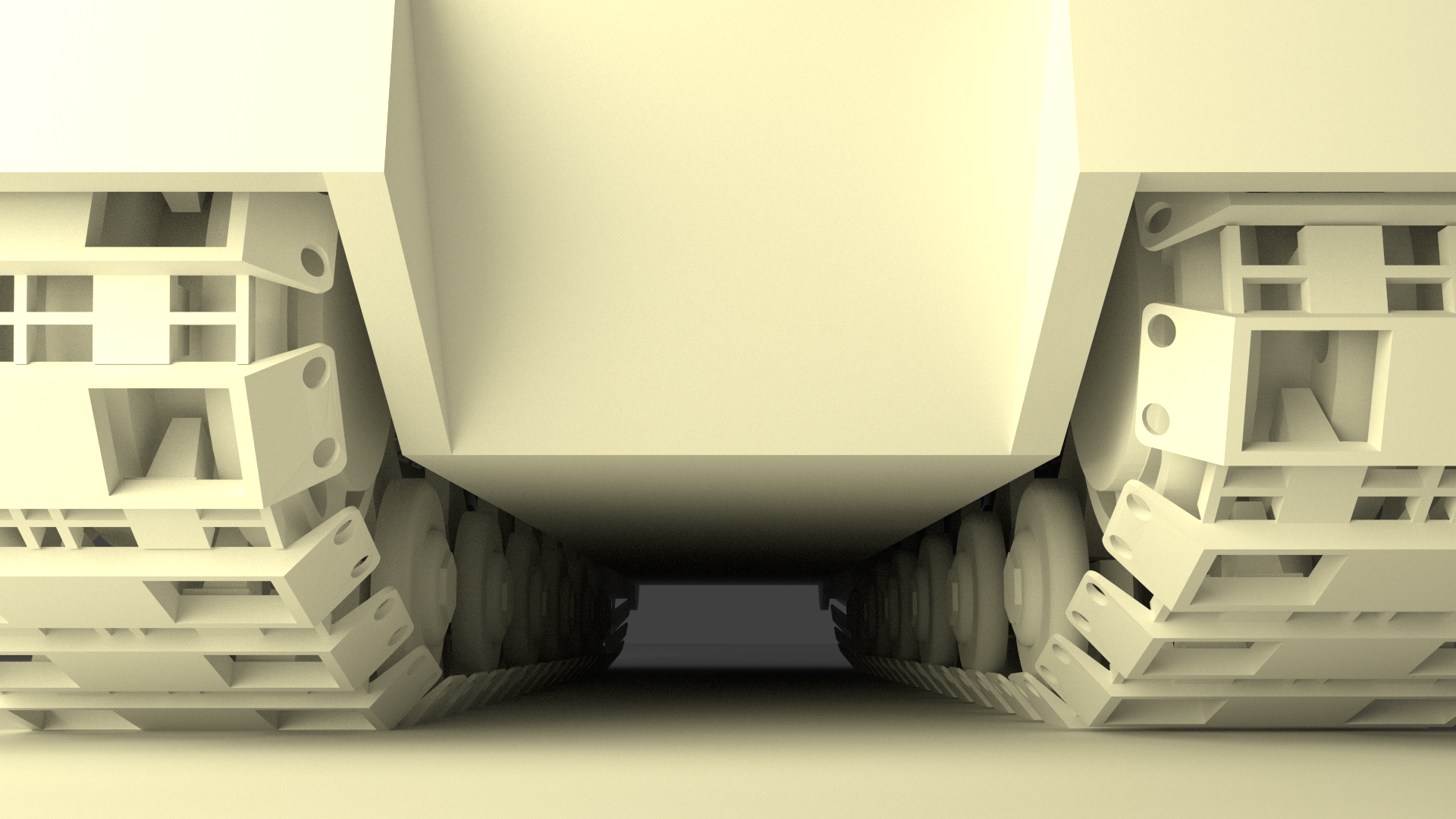
Assembly Chassis
The honesty of the mouse continues to haunt us. He has 48 track rollers, by the way (while the T-34 has 10). In staggered order. At this stage, I actively use Array and Mirror.
Details
Caterpillar assembly
The final and longest step.
The method outlined in the “Caterpillars Sources” section assumes the presence of only one type of track. The chthonicity of the mouse gives us 2 types. So I made two caterpillars in the same place - one for each type of track.
And one more nuance. If you just make an array that follows a curve, then the array elements that are on the curves of the curve will also be bent (this can be seen in the video with the creation of a profile curve), which is logical - the modifier itself is intended for the curvature. And the tracks of the tank are iron and should not bend.
Abnormal for the modifier, but the solution we need is the following - enter an intermediate plane and use procedural polygon duplication.
Details
Algorithm:
I did it all in a slightly different order, but the steps were the same.
Since the video turned out very well, I cut out the creation of one of the tracks and raised the moments of filling the titles.
- Create a curve profile (we already have).
- We create an auxiliary plane - it will be a) a donor of polygons for procedural polygon duplication of tracks and b) a guide for correct orientation of multiplied tracks. As follows from point a), how many polygons this plane has - so many tracks there will be a caterpillar. And you can apply Array to the plane, and everything will work.
- For the plane, set the Curve on the profile. Thin moment - Curve works as it should in the event that the origin of the curve and the element on which the Curve is hung should coincide. It is impossible to understand, it can only be remembered.
- Create the actual truck (also already there). Making it a child (this is important) with respect to the auxiliary plane. On the plane we include on-polygon duplication.
- To control a double caterpillar, we create an Empty-object and set the Copy Location to this object at the auxiliary planes. As a result, when the Empty is moved along the Y axis, both tracks turn.
- Repeat points 2-5 for the second type of tracks.
- We shift one of the tracks (any) half a period ahead. You need to move the auxiliary plane.
I did it all in a slightly different order, but the steps were the same.
Since the video turned out very well, I cut out the creation of one of the tracks and raised the moments of filling the titles.
Details and result
Actually, at this point the mouse is ready and assembled, it remains to hang small parts, which, by the way, give 80% presences. I will not tell here how to do them - I think that by this time it is already self-evident (we cut, scale, extrude, merge, fill). It is only necessary to remember to tie the parts to parts of the tank (parenting or Child of or in general Ctrl-J - as you see fit).
Modelka, obtained after assembling the tracks - here . I added a gun for a sense of completeness.
And here - a model with a couple of glued parts.
In both files there are drawings.
A license, if this is of concern to someone, is a complete copyleft.
Conclusion
This is the final series in the “Simple Blender” cycle. Thank you all for your attention and interest. For me it was a very unusual experience - to publish in the media, and even from a personal point of view. And in order to understand if Blender is simple, please participate in the survey.
And it would be interesting to hear the comments of 3D artists working in other packages - what would be the process of modeling some parts of a tank (a tower there, or a mask) - just to compare. Anyway, comments are welcome.

Answered a comment called.
Source: https://habr.com/ru/post/273543/
All Articles