Simple Blender. Part 3
KDPV 3. Incomplete disassembly
In the previous part I wrote about objects. This part is about geometry.
')
Geometry
By tradition, retreat
No matter how much I want to make the post smaller (and more pictures), such a serious topic as geometry still requires understanding.
Not understanding the basics of computer graphics, in 3D modeling there is not much to achieve (except to be engaged in sculpting, but there is already creativity). Therefore, just below, I will take a very mentor tone, simultaneously plunging into the depths of the basics. If you know how the triangle differs from the polygon, and that one from the normal, then safely and decisively skip.
Basics of computer graphics. Quite the basics, honestly.
In computer representation, a 3-dimensional object is usually represented as a set of points with coordinates, edges between them and faces that are stretched on these edges.
“Usually” - because there are at least voxels .
More details.
The point (vertex) is the basis and the basis, it is the alpha and omega, no points - no way. Points can and do exist by themselves. Characteristics of the point - coordinates.
Edge (edge) - a connection of exactly two points. In Russian it is a “three-dimensional segment”. The characteristics of the edge are the points forming it and, in fact, the line itself.
So, the ribs create a frame. On this framework, then stretches something, for the sake of what the whole ballet is usually made ( unusual ) - the edges. Or polygons. Or surface. I will take the liberty to further use my terms - simply because it is more convenient for me.
So. The surface (polygon, face) is stretched onto a closed “frame” of edges. The minimum possible number of edges in the frame is three, which is obvious, otherwise it will be a stick.
Now the main point: a triangle of 3 edges can not be bent. It is important. He has all the edges always lie in the same plane. If you pull at any of its vertices (the points that belong to its edges), the surface does not break. This property is critical for computer calculations, therefore, in principle, after the point and the edge goes:
A triangle is a surface stretched over a closed frame of 3 edges. Characteristics: edges, vertex coordinates, and normal. Normal is a purely computer characteristic necessary for calculating the lighting. If you are never going to render your models, or export to another program, then forget about the normal. If you are going, then here is the explanation. The triangle has 2 surfaces. When we say that light falls on the surface of a triangle, we need to specify (this is required by the calculation algorithms) which side is expected to fall, in other words, to indicate the outer side of the triangle. A normal is a vector emerging from a triangle at a right angle to its surface to the outside. Some programs (not Blender) simply do not draw the inner side of the triangle, there may be holes. The point and edge have no surfaces, so they have no normal either.
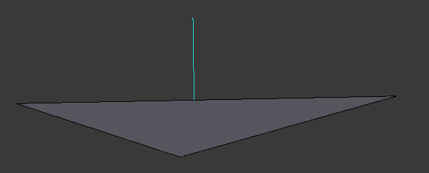
Figure 1. A triangle (gray) with a normal going out of it (blue line). As you can see, the outer side of this triangle is at the top and is not visible to us. There are programs that do not render triangles if the outer side is not visible from the camera. On the render of such a program, in the place of the depicted triangle, it would be what is behind it.
This, in principle, could be limited, since the triangle is enough to pave any surface with a fairly good approximation. The word “enough” is key here. The more triangles - the greater the load on the system. The process of starting tiling with triangles is called triangulation. The process of increasing the detail of an already triangulated surface is tessellation. Video cards, OpenGL, DirectX operate with triangles. The principle of minimum necessity.
However, when we speak about modeling, human laziness comes into its own. If they tell me to triangulate the frame shown in Figure 2, then I will. And if they tell me that there are algorithms for automatic triangulation, then I will try to automate the process. There are such algorithms. Therefore, the next step appears - the polygon.
A polygon is a set of triangles lying in the same plane and adjoining each other by edges.
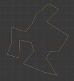
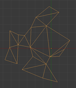
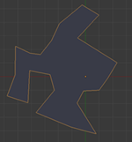
Figure 2. On the left - a closed frame of edges, in the center - its triangulation (personally done!), On the right - a polygon on this frame.
Joining together the triangles (or polygons), lying in different planes, we get what is called an “object”.
It is important to understand that, for example, the concept of “point” has its obligatory attributes - coordinates, but the concept of “object” does not have them. Even the closeness of its surface is optional. Even joining polygons is optional. Two points is an object. A point is also an object. If you, as the author of the model, decided so - it means that it will be within the framework of this model.
Moreover, in 3D editors there is an object “Empty” (used as an auxiliary). He has only coordinates. There is no point, but there are coordinates.
Summarizing. Geometric concepts in 3D modeling, starting from below: point, edge, triangle (and the derivative is a polygon). But an object is just a container for geometric elements.
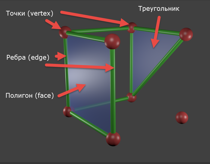
Figure 3. Molecular, so to speak, object model. This object consists of 8 points (one is not tied to anything), 9 edges, a triangle (not signed in English intentionally) and a polygon (calculated automatically, actually consists of two triangles).
“Usually” - because there are at least voxels .
More details.
The point (vertex) is the basis and the basis, it is the alpha and omega, no points - no way. Points can and do exist by themselves. Characteristics of the point - coordinates.
Edge (edge) - a connection of exactly two points. In Russian it is a “three-dimensional segment”. The characteristics of the edge are the points forming it and, in fact, the line itself.
So, the ribs create a frame. On this framework, then stretches something, for the sake of what the whole ballet is usually made ( unusual ) - the edges. Or polygons. Or surface. I will take the liberty to further use my terms - simply because it is more convenient for me.
So. The surface (polygon, face) is stretched onto a closed “frame” of edges. The minimum possible number of edges in the frame is three, which is obvious, otherwise it will be a stick.
Now the main point: a triangle of 3 edges can not be bent. It is important. He has all the edges always lie in the same plane. If you pull at any of its vertices (the points that belong to its edges), the surface does not break. This property is critical for computer calculations, therefore, in principle, after the point and the edge goes:
A triangle is a surface stretched over a closed frame of 3 edges. Characteristics: edges, vertex coordinates, and normal. Normal is a purely computer characteristic necessary for calculating the lighting. If you are never going to render your models, or export to another program, then forget about the normal. If you are going, then here is the explanation. The triangle has 2 surfaces. When we say that light falls on the surface of a triangle, we need to specify (this is required by the calculation algorithms) which side is expected to fall, in other words, to indicate the outer side of the triangle. A normal is a vector emerging from a triangle at a right angle to its surface to the outside. Some programs (not Blender) simply do not draw the inner side of the triangle, there may be holes. The point and edge have no surfaces, so they have no normal either.
Figure 1. A triangle (gray) with a normal going out of it (blue line). As you can see, the outer side of this triangle is at the top and is not visible to us. There are programs that do not render triangles if the outer side is not visible from the camera. On the render of such a program, in the place of the depicted triangle, it would be what is behind it.
This, in principle, could be limited, since the triangle is enough to pave any surface with a fairly good approximation. The word “enough” is key here. The more triangles - the greater the load on the system. The process of starting tiling with triangles is called triangulation. The process of increasing the detail of an already triangulated surface is tessellation. Video cards, OpenGL, DirectX operate with triangles. The principle of minimum necessity.
However, when we speak about modeling, human laziness comes into its own. If they tell me to triangulate the frame shown in Figure 2, then I will. And if they tell me that there are algorithms for automatic triangulation, then I will try to automate the process. There are such algorithms. Therefore, the next step appears - the polygon.
A polygon is a set of triangles lying in the same plane and adjoining each other by edges.
Figure 2. On the left - a closed frame of edges, in the center - its triangulation (personally done!), On the right - a polygon on this frame.
Joining together the triangles (or polygons), lying in different planes, we get what is called an “object”.
It is important to understand that, for example, the concept of “point” has its obligatory attributes - coordinates, but the concept of “object” does not have them. Even the closeness of its surface is optional. Even joining polygons is optional. Two points is an object. A point is also an object. If you, as the author of the model, decided so - it means that it will be within the framework of this model.
Moreover, in 3D editors there is an object “Empty” (used as an auxiliary). He has only coordinates. There is no point, but there are coordinates.
Summarizing. Geometric concepts in 3D modeling, starting from below: point, edge, triangle (and the derivative is a polygon). But an object is just a container for geometric elements.
Figure 3. Molecular, so to speak, object model. This object consists of 8 points (one is not tied to anything), 9 edges, a triangle (not signed in English intentionally) and a polygon (calculated automatically, actually consists of two triangles).
Having emerged from the depths of the foundations, now I will dive into the depths of reasoning. This part is also optional, but will help to better understand my position.
About laziness and difference in ideology.
In the last series I wrote about primitives. “Primitive” is, by and large, a marketing term. I can't call Susanna primitive. In fact, primitives should be called "basic objects" or "standard objects" - well, something like that. But, to argue about well-established terms is a thankless task. Primitive is so primitive.
So, primitives, as you already understood, are not the very bottom (I am in the good sense of the word) of modeling. The very bottom of the simulation is, as you already understood, the points, edges and faces of which they are composed. Like any other 3D object.
Primitives are nothing special. They are available immediately because they are commonly used and have a simple form that helps to apply the technique of Michelangelo - look at the simulated object, estimate the most similar primitive, create it and cut off the excess. And from the program to the program the set of primitives varies. In Max, there are even “extended primitives” (besides the usual ones), including a corner, a cylinder with chamfers, a capsule, a node, etc.
To improve the usability of the primitives, they identified their key parameters inherent (for example, the radius of the ball) and made it possible to set these parameters at the start. After setting the parameters and confirming the creation, the 3D package according to the corresponding script simply places the points, pulls on the edges and triangles with these parameters. Voila - primitive ready.
Primitives are just a library to speed up work.
As is already clear, modifiers work at the level of the geometry of objects, and not of the objects themselves. An object is just a container. The work of any modifier can be done at the same level of geometry and hands, it's just longer. Modifiers are from the same opera as the polygon and primitives.
The “Create Ball” button in Blender does exactly what I wrote above. The program creates geometry. You can specify the exact parameters of the sphere, but only once - when creating. If you remove the selection from the ball, you will not specify the parameters again. Blender in this sense is hardcore compared to max, where ...
“Create ball” in max is a stack command. This is a procedure. It is placed at the bottom of the stack, selecting it in the stack can re-specify the parameters of the sphere: radius, number of segments, etc. It does not generate geometry (in the sense that it can be edited), it generates the basis for subsequent modifiers. Max seems to be hinting to us: “Hey, don't dig through the dots! I have one hundred million modifiers and even extended primitives, just combine! ”Working with geometry in max is an exception. So much so that an editable geometry modifier has been entered. Think about it - a modifier that simply allows you to work manually with geometry. But still, in Max you can work with geometry, so ...
So it turns out that Blender is not as flexible as the max: I don’t like the resulting detailing - recreate the primitive, specify the necessary parameters, and repeat the same operations. Darkness. Like.
If you make a ball in max, apply the “Edit Mesh” modifier, move a couple of vertices / edges / faces, and then click on the “Create ball” stack command (well, I don’t like the details, I want to use the architectural perfection of Max), then the following will happen:
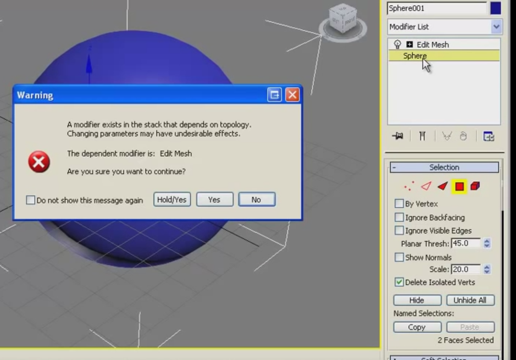
Figure 4. Max. Return to the top of the stack after manual work with geometry. Since Max has not been around for a long time, he was ripped out of the video, sorry for the quality.
Max puts the responsibility on the user, because miracles do not happen: if I moved two adjacent polygons in opposite directions, and then in the stack I reduced the scope of the scope 4 times - when climbing up the stack, where should I move the polygon located on the previous two?
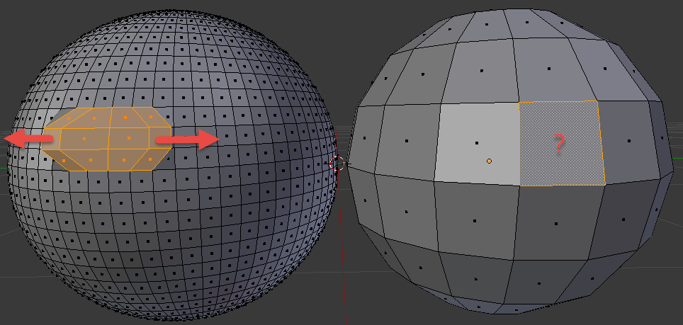
Figure 5. Max selection dilemma. We moved one polygon to the left, another - to the right, then rolled back to the start of the stack and reduced the detail. Where to move the landfill?
In fact, the max stack is powerless here and in fact the sphere parameters in max are also set once and for all. All of the above is true if we are talking about manual work with geometry (which includes a sweep). If it is only modifiers, then here is the max in its own right.
But in Max there is align to, but Blender is all filonite (addons are non-shield).
Summarizing: max expects that you start with the concept of a primitive and will operate with modifiers, and in Blender - with the geometry of a primitive and will operate with geometry (but there are also modifiers).
Primitives
In the last series I wrote about primitives. “Primitive” is, by and large, a marketing term. I can't call Susanna primitive. In fact, primitives should be called "basic objects" or "standard objects" - well, something like that. But, to argue about well-established terms is a thankless task. Primitive is so primitive.
So, primitives, as you already understood, are not the very bottom (I am in the good sense of the word) of modeling. The very bottom of the simulation is, as you already understood, the points, edges and faces of which they are composed. Like any other 3D object.
Primitives are nothing special. They are available immediately because they are commonly used and have a simple form that helps to apply the technique of Michelangelo - look at the simulated object, estimate the most similar primitive, create it and cut off the excess. And from the program to the program the set of primitives varies. In Max, there are even “extended primitives” (besides the usual ones), including a corner, a cylinder with chamfers, a capsule, a node, etc.
To improve the usability of the primitives, they identified their key parameters inherent (for example, the radius of the ball) and made it possible to set these parameters at the start. After setting the parameters and confirming the creation, the 3D package according to the corresponding script simply places the points, pulls on the edges and triangles with these parameters. Voila - primitive ready.
Primitives are just a library to speed up work.
Modifiers
As is already clear, modifiers work at the level of the geometry of objects, and not of the objects themselves. An object is just a container. The work of any modifier can be done at the same level of geometry and hands, it's just longer. Modifiers are from the same opera as the polygon and primitives.
Actually, the difference of ideologies
The “Create Ball” button in Blender does exactly what I wrote above. The program creates geometry. You can specify the exact parameters of the sphere, but only once - when creating. If you remove the selection from the ball, you will not specify the parameters again. Blender in this sense is hardcore compared to max, where ...
“Create ball” in max is a stack command. This is a procedure. It is placed at the bottom of the stack, selecting it in the stack can re-specify the parameters of the sphere: radius, number of segments, etc. It does not generate geometry (in the sense that it can be edited), it generates the basis for subsequent modifiers. Max seems to be hinting to us: “Hey, don't dig through the dots! I have one hundred million modifiers and even extended primitives, just combine! ”Working with geometry in max is an exception. So much so that an editable geometry modifier has been entered. Think about it - a modifier that simply allows you to work manually with geometry. But still, in Max you can work with geometry, so ...
So it turns out that Blender is not as flexible as the max: I don’t like the resulting detailing - recreate the primitive, specify the necessary parameters, and repeat the same operations. Darkness. Like.
If you make a ball in max, apply the “Edit Mesh” modifier, move a couple of vertices / edges / faces, and then click on the “Create ball” stack command (well, I don’t like the details, I want to use the architectural perfection of Max), then the following will happen:
Figure 4. Max. Return to the top of the stack after manual work with geometry. Since Max has not been around for a long time, he was ripped out of the video, sorry for the quality.
Max puts the responsibility on the user, because miracles do not happen: if I moved two adjacent polygons in opposite directions, and then in the stack I reduced the scope of the scope 4 times - when climbing up the stack, where should I move the polygon located on the previous two?
Figure 5. Max selection dilemma. We moved one polygon to the left, another - to the right, then rolled back to the start of the stack and reduced the detail. Where to move the landfill?
In fact, the max stack is powerless here and in fact the sphere parameters in max are also set once and for all. All of the above is true if we are talking about manual work with geometry (which includes a sweep). If it is only modifiers, then here is the max in its own right.
But in Max there is align to, but Blender is all filonite (addons are non-shield).
Summarizing: max expects that you start with the concept of a primitive and will operate with modifiers, and in Blender - with the geometry of a primitive and will operate with geometry (but there are also modifiers).
Work with geometry
Turning point
As I wrote above, an object in Blender is a container. In addition to the geometry itself (mesh), it also has a name, a stack of modifiers, materials applied, and origin is a turning point. It is set by default to the center of mass of the primitive, but it can be moved (or it will leave itself, being not where it is necessary - an example is given below). To install origin, select the object and, without removing the selection, put the 3D cursor in the right place and press Shift-Ctrl-Alt-C (or the space - Set origin, if you feel sorry for the fingers).
Below is an illustration.
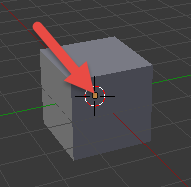
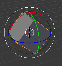
Figure 6. On the left is a cube with a pivot point (a dirty orange square), set to the center of mass by default. On the right - the result of the basic operation of cube rotation (specifically included the display of controllers for clarity) - the cube is spinning in place.
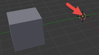
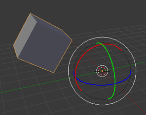
Figure 7. On the left a cube with a displaced turning point (I created a cube in the center of coordinates, shifted it to the side, pressed Shift-S, selected Cursor to Center, and then Shift-Ctrl-Alt-C and selected “Origin to 3D cursor”) . On the right - the result of the basic operation of cube rotation (specifically included the display of controllers for clarity) - the cube does not rotate in place, but in a circle.
Ui
In the first series, I mentioned that Blender focuses on tasks, discarding the unnecessary at the moment. In addition to the layouts, this also applies to such a concept as “mode of operation”.
Here is its indicator - a drop-down list with almost all available modes:
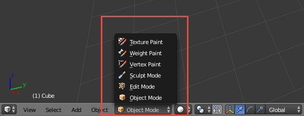
Figure 8. Possible Blender modes of operation (there is also a posture setting mode, but it is available only when a bone is selected). When switching, pay attention to how the menu items closest to the indicator change depending on the operation mode.
Up to now we have been working in Object Mode. In it, the minimum unit of work is the object. Maximum - the whole scene.
To work with geometry, it is necessary to a) select the object of interest and b) go to Edit Mode. The hot key for switching between Object and Edit Mode is the Tab key (I remind you that the object should be highlighted). You can, of course, use the drop-down list of modes. Further, the mode of operation with geometry, I will call EM - abbreviated from Edit Mode. Mode of work with objects, respectively - OM.
The minimum unit of work in EM is a point. Maximum - all object geometry.
So, create a primitive, press Tab and see the following:
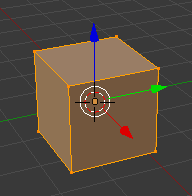
Figure 9. Object mapping for work at the level of geometry.
We see points (at the corners), edges and polygons. And then there are 2 questions:
- Why is all geometry highlighted?
- How to move a specific point / edge / face?
All geometry is selected because you just created a primitive in OM and then moved to EM. Blender does not know what exactly you want to work with and offers to work with all geometry at once (you could not offer at all, but friendly people sit in BF). If you pull the controller right now and move the whole geometry to the right, you will see how the geo- etry has left, but origin has remained in place. Slide and return to OM, then rotate the die. That's why I wrote about origin. And that's why EM is the mode of operation with geometry. Origin is not the geometry of the object, it is a separate characteristic of the object.
At this point, it is appropriate to say that at the stage level Blender operates precisely and only with objects and their combinations. You can't just create and create a geometry without an object — it will have neither origin, nor name, nor anything else. And if you try to give a name to geometry, then again this is an object. Geometry is an important part of an object, but only a part is critical.
So, how to select the desired element (a pair of points or an edge, for example)? Very simple. First you need to tell Blender what type of geometry you are interested in. It is possible through UI:
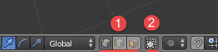
Figure 10. Buttons 1 switch between points, edges and edges, button 2 turns on / off backfacing (accounting for elements on the back surface of the object).
Or you can press Ctrl-Tab in EM:
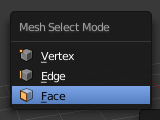
Figure 11. The menu for selecting the way to work with geometry. Works cursor, mouse, and even buttons 1,2,3.
Handling geometry
Blender, unlike Max, does not allow to operate with such a concept as a triangle. He operates a polygon. And he himself cuts it into triangles. If you need total control, make all the polygons triangular. Figure 3 displays these realities - in Blender, those elements are available that have an English name in the figure.
Item selection
OM / EM
Everything written below applies to OM:
- The personal element selection by PCM works. Shift - RMB adds / removes from the current selection.
- “Select all that you can” / “deselect all selections” - press A. Or the 3D menu item of the Select -> (De) select All area. One of the most frequently pushed by me.
- Select by frame (taking into account the installed back-fusing) - B. Or Select -> Border Select. Does not remove the already existing selection, which is important. It helps when working with points.
- Select around (taking into account the established back-fusing) - C. Or Select -> Circle Select. I use rarely.
EM-only
In general, since there are LOTS of elements in any more or less nontrivial geometry, there are much more ways to choose in EM than in OM. I will not list all of them - it's easier to look at Select (switching to EM), there are selection modes that apply only to geometry. Rarely used, but sometimes very much help out.
Basic operations on elements
Transfer, rotate, scale works the same way as in OM.
Upd. Leopotam (who took on the role of a strict editor of my opuses, for which he thanks) noticed that origin is only one of the possible turning points. Others are available, the choice can be made here:
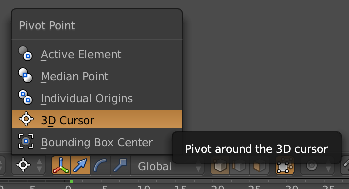
Handling elements
Again, geometry is, above all, a multitude of related (!) Elements. And there are more possible operations for them than for objects. For example, the operation Subdivide (divides the element into a specified number of parts). Basic operations are displayed in the T panel. All is in the Mesh menu. Some of them are context-sensitive, consider this (Subdivide is meaningless for a point. And for an object too, how to divide an asymmetric object into equal parts?).
When you call the operation at the bottom of the detailed settings panel, you can specify the parameters of the operation.
I will indicate here the most frequently used operations by me:
- Extrusion — select the item (s) and press E. Creates a duplicate selection, ties it to the original, and transfers the selection to the duplicate. After which the selection can be moved. Difficult to explain, easier to try.
The reason for the appearance of random duplicates - the remaining unfinished operations can be rolled back by Esc. Extrusion is 2 operations - the creation of geometry and its actual transfer. By Esc only the transfer is canceled, the geometry remains. To remove it, press Ctrl-Z.
If you suspect that you have a lot of unnecessary points in one place, you can select this region and call the operation “Remove doubles”. The indicator that appears in the menu area will tell you whether your suspicions were justified. - Create a new item. Select an item and click in the right place Ctrl-LMB. In the place of pressing, an element of the same type will be created, with connections stretched to the parent (edge for points, polygon for edges and a set of polygons for polygons).
- Connecting - select the items and press F.
I want to separately draw attention to the fact that the creation of primitives is available in EM. When creating an object, the geometry (and only) of the newly created primitive will be added to the current geometry.
Work with normal
Also, when working with geometry, sometimes there are problems with normals. To understand the current situation, you will need to look through the normals:
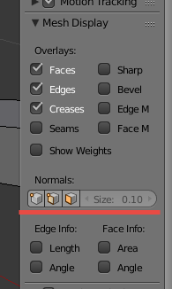
Figure 12. UI display of normals. On the left - the display mode buttons, on the right - the length of the vector (in the case of tricky geometry it helps, if unscrewed to the maximum - see where it breaks through).
And to manage them - the tab "Shading / UVs" (which is logical, since the normals are needed for lighting) panels by T.
Conclusion
Using the above techniques, it is possible to make the same object in half a minute as in Figure 3. You can practice. The delete operation requires a) highlight the deleted and b) click Delete (in the case of geometry, you may be asked what to delete. If you need to delete a polygon without touching its edge or edge without touching its point, choose the option where there is only word):
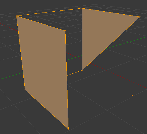
Figure 13. An example of an object.
In the next series - management.
Source: https://habr.com/ru/post/272853/
All Articles