Cisco Switch and Hewlett Packard Enterprise Switch Virtualization Technologies

Today I would like to talk about two fairly similar switch virtualization technology, which allows you to combine several switches into one logical one. It will be about Cisco Virtual Switching System (VSS) technology and HPE Intelligent Resilient Framework (IRF). As part of this article, we will take a closer look at how VSS technology works, after which we will talk about IRF technology.
Both technologies (VSS and IRF) allow us to combine switches using ordinary Ethernet ports. In general, these technologies can be attributed to the technology of stacking. But both vendors still try to call them virtualization technologies. Cisco generally avoids the word stack in relation to VSS.
Cisco VSS
')
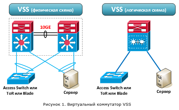
VSS technology allows you to combine two physical switches into one logical switch. But unlike more classic stacking technologies (StackWise, FlexStack), not any specialized cables, but Ethernet ports are used to connect switches between each other. Thus, switches can be located at a relatively large distance from each other.
After merging, the switches begin to operate as one logical (Figure 1). Both switches are active and provide packet forwarding. In this case, both switches are controlled by one of the devices. In other words, the data processing level (data plane) is active on both devices. But the level of control (control plane) is only on one. Recall that the control plane (I propose to use the foreign name in the future) is responsible for the logic of the switch: handling all network protocols (L2 / L3), forming the routing table, filling in the CEF, ACL, QoS tables, etc.
VSS technology is supported on the following Cisco switches:
- Cisco 4500E and 4500X
- Cisco 6500E and 6800
But to take any two such devices and combine them using VSS technology will not work. First, not all supervisors, not all line cards, and also not all service modules support VSS technology. For example, for the 6500E, VSS technology is supported on the Sup720-10GE and Sup2T supervisors. Secondly, VSS technology works only between identical platforms, for example, between two 4500X or two 6500E + Sup2T. Packing devices (line cards and service modules) may vary. The chassis size for 4500E and 6500E switches may also vary. There are many nuances, so it is highly desirable to see the actual requirements for hardware, software versions and licenses on the vendor's website.
After we combined the two switches together, the overall system performance is doubled. This is because both switches are responsible for handling packets. Thus, we get:
- up to 1.6 Tbps for 4500X series switches
- up to 1.8 Tbit / s for 4500E series switches with Sup 8-E supervisor,
- and up to 4 Tbps for 6500E / 6800 Series Switches with Sup2T Supervisor.
The VSS architecture is shown in Figure 2. One of the switches is chosen as the main switch, the second switch as the backup switch. On the main switchboard, the control plane becomes active (Active), and on the backup switch it enters the Hot Standby state.

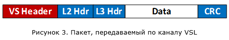
The active control plane controls the operation of both switches. Also in the process of operation, the state is constantly synchronized between the active control plane on the main switch and the control plane on the backup switch to ensure fault tolerance. Management and synchronization are performed through a special channel - Virtual Switch Link (VSL).
The VSL channel is a direct connection between two switches (no intermediate devices allowed). To ensure the VSL channel, the switches are connected to each other through normal Ethernet ports. But when I talk about ordinary ports, I’m a little cunning. As you might guess, these ports also have certain requirements and these requirements vary depending on the switch platform. A special header - Virtual Switch Header (32 bytes long) is added to all packets that are transmitted through the VSL channel:
VSL can consist of several physical channels (which is actually recommended to do). This is necessary for the resiliency of our system, as well as obtaining the necessary bandwidth. Aggregation is performed using PAgP or LACP protocols. Those. we can maximally have 8 active channels combined into one logical VSL. For example, if we use 10 Gbit / s ports, we will get up to 80 Gbit / s with the aggregation of 8 such channels.
I think many have noticed that the VSL channel is analogous to a stack bus. Therefore, it is very interesting to look at the traffic that goes through it:
- system control traffic (traffic of protocols supporting the operation of the VSS virtual switch, including state synchronization between the switches),
- network control traffic (traffic addressed to the control plane but received by the backup switch: CDP, VTP, STP, EIGRP / OSPF, etc.),
- user traffic (including broadcast and multicast),
- service traffic (for example, SPAN).
During the discussion, we somehow dwell in more detail on each type of traffic.
So, after the switches are started, protocols go into battle that provide the initial initialization of VSS:
- Link Management Protocol (LMP)
- Role Resolution Protocol (RRP)
LMP verifies that the VSL link is up and the devices see each other. RRP checks the hardware and software compatibility of devices, and also determines who will be the main switch and who is the backup.
Control plane on the main switch performs two functions. The first one provides the logic of the switch operation: programming the switch based on the configuration, processing all network protocols (L2 / L3), creating a routing table, CEF tables, managing ports, etc. The second function is to populate all the hardware tables (FIB, Adjacency, ACL, QoS, etc.) on both switches to ensure the processing of user traffic (at the hardware level). The control plane on the backup switch is in a hot standby state. At the same time, the state of the active control plane is constantly synchronized with the backup one. This is necessary in order to ensure the continuous operation of our virtual switch in case of failure of the main physical switch.
The following information is synchronized: device boot parameters, their configuration, the status of network protocols and various tables (running on the active control plane), the state of devices (line cards, ports).
The transfer of control data and state synchronization between the main and backup switches are performed using specialized protocols:
- Serial Communication Protocol (SCP) - provides communication between the processor and the line cards (both local and on the remote switch)
- Inter-process Communication Packets (IPC) - provides communication between processors of distributed devices
- Inter-Card Communication (ICC) - provides communication between line cards
All of these protocols relate to the system control traffic that is transmitted between the switches over the VSL channel and form a logical control channel (Inter-Chassis Ethernet Out Band Channel - EOBC).
State synchronization between switches is handled by stateful switching (SSO). This mechanism appeared quite a long time ago. For example, it is used to reserve supervisors within a single switch 6500. It is also used in VSS technology (they didn’t come up with something new). But as we remember, SSO does not allow to synchronize the status of routing protocols. So, when switching to a backup switch, dynamic routing protocols are started from scratch. That automatically terminates all L3 connections with remote devices. Those. we get a temporary loss of communication with the outside world. To solve this problem, SSO technology works in conjunction with Non-Stop Forwarding (NSF) technology. This technology performs the following tasks: it ensures the transmission of L3 packets at the moment of switching (it actually freezes the old records of all routes), notifies remote routers that they do not need to break the connection, and also requests them all the necessary information to build a new routing table. Of course, the remote devices must in this case also support the NSF technology (to be NSF-aware, so to speak).
By the way, for reference: the backup switch takes up to 13 seconds to completely restart the dynamic routing process. Therefore, without the NSF technology would be very sad.
And how quickly will switching to the second switch in case of the first failure? The vendor in this regard gives the average figure of 200 ms. For the 6500E (apparently for the 6800 too) in some cases it can reach 400 msec (as it were, the costs of architecture distribution).
As for the control plane, one more thing is worth noting. Since the active control plane is only on one of the switches, all traffic of the network protocols is processed by them. For example, dynamic routing protocol traffic (OSPF, EIGRP, etc.) must ultimately fall on the active control plane. So, if he first got to the backup switch, this traffic will be transmitted to the main switch through the VSL channel. In this case, the response packets can be sent directly from the main switch (priority option), and can be transmitted through the backup. It depends on several things: the type of network protocol and the presence of a direct channel from the main switch to the receiver.
If we are dealing with 4500E / 6500E / 6800 switches, we can install two supervisors in each of them (dubbed duplicated, so to speak). VSS also supports this configuration (called Quad-Supervisor). This is necessary in the case when we do not want to lose the overall system performance, in case of failure of one of the supervisors. For all options except Sup2T, the second supervisor in the chassis works in a cold standby (Route Processor Redundancy). This means that the second supervisor goes into working mode (becomes backup in the VSS section) only after the restart of the entire chassis. In the case of Sup2T, the second supervisor in the same chassis works in SSO mode and no reboot is required.
Now let's talk about transferring user traffic through a VSS virtual switch. Still, this is his main task. One of the main reasons for using VSS is the ability to aggregate multiple channels coming to different switches (in terms of Cisco, Multichassis EtherChannel (MEC)). We are talking about connecting to a virtual switch external devices (for example, other switches).
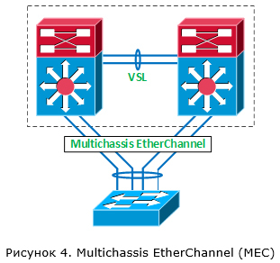
When we aggregate several channels into one logical one within VSS, one of the dynamic aggregation protocols (PAgP or LACP) or static EtherChannel (ON mode) can be used. For the distribution of traffic within the logical channel responsible mechanism based on the hash function. The hash function is applied to certain header fields of the transmitted traffic. For example, the hash function may be applied to the value of the IP address of the sender. In this case, if at us two channels are aggregated, then on the first channel traffic flows will be transmitted, whose IP addresses of the sender are even, and on the second channel - odd. This allows you to distribute traffic flows between different channels combined into one etherchannel. In more complex cases, several parameters can influence the choice of a channel at once (for example, Src IP + Dst IP + Src Port + Dst Port).
In the case of VSS, the following rule always works: first of all, local communication channels are used to transmit traffic within the MEC (Figure 5). This is done in order not to load the VSL channel. I note that this statement for the 6500E / 6800 is true for both the MEC case and the Equal Cost Multipath case (if the connectivity between the virtual switch and the neighboring device goes through separate L3 channels).

And it does not matter what we have the total bandwidth for each switch. In our example, even with a double connection between SW2 and SW3, packets arriving at SW1 and addressed to recipients for SW3 will always go through a single local port. But if this connection is broken (or, initially, SW3 switch was connected only to SW2), all traffic will go through the VSL channel (Figure 6).

From here we conclude that the recommended VSS operation scheme is the connection of devices to both VSS switches at the same time (Figure 7). In this case, our traffic will be distributed between both VSS switches and we will get an almost twofold increase in the performance of the entire system compared to one switch. Otherwise, we load the VSL channel and lose in the overall system performance (spending the power of both switches on processing one traffic stream).

To improve the performance of the mechanisms for balancing traffic within the MEC channels, the following functions have been added for VSS technology:
- Adaptive hash distribution - when adding and removing channels, the system tries to keep traffic flows on the same channels as they were.

In our example (Figure 8), when adding the third channel, only the 7th and 8th traffic flows will be affected. - The options for balancing traffic between channels are extended (for example, a VLAN number can be used), and an additional pseudo-random Unique ID is also used. All this is added to prevent the effect of polarization of traffic (when traffic is mainly transmitted through certain channels, underloading others).
In order to finish with user traffic, I would like to note one more thing. Through the VSL channel will also be transmitted traffic that is sent to all devices within the VLAN. Such traffic can include broadcast traffic, traffic for which there is no data on the recipient's MAC address (unknown unicast) and multicast traffic.
So, we found out that both switches handle traffic, while all management is focused on one of them. The VSL channel is used as a common connecting bus through which at least control and synchronization information is transmitted. Through this same channel, the backup switch learns that the main switch is "dead." But what will happen if this channel breaks, while both switches will be healthy? The answer is simple, the main switch will remain active, but the backup switch will consider that his colleague has failed, and accordingly will also become active (this is all about the control plane). And since the configuration of these switches is one, we will get two absolutely identical devices with identical addressing on the network. I think it is not necessary to say what this will lead to. In order to avoid such a situation, at least you should not break the VSL channel. But it does not always depend on us, so there is a mechanism that allows you to minimize the consequences of breaking the VSL channel. This mechanism uses one of three methods for detecting a faulty situation:
- Enhanced PAgP
- Fast hello
- IP BFD
After it is determined that both switches have become active due to a VSL link break, the following actions are performed:
- A switch that was active before the VSL link broke down disables all interfaces except VSL and interfaces for which it is specified in manual mode that they do not need to be disabled. This behavior allows the network to continue to work further, though on a single switch, but without collisions.
- As soon as the VSL channel is restored, the switch that was initially active will reboot. After reboot, it will become backup.
Thus, when a situation occurs with two active switches, in the end, the one that was initially redundant remains active. Let's see how each of the voiced methods works.
In the case of Enhanced PAgP (approx. PAgP - proprietary protocol), an external device is used as a “litmus test”. Each VSS switch sends a special PAgP message through local ports within the same MEC logical channel through which the external switch is connected (Figure 9). This message contains the identifier of the active VSS switch. Having received the ePAgP packet, the remote device sends it in the opposite direction. If everything is fine, both switches send the same VSS active switch ID. If both switches become active, each of them will send messages with its own identifier (Figure 10). And since the remote device sends such messages back, both switches will realize that a bad situation has occurred.
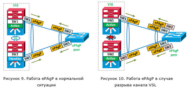
And how quickly will the failed situation be detected in this case? As soon as the switch, which was originally a backup, becomes active, it immediately sends an ePAgP message with its ID. Thus, the time to detect a failed situation is a fraction of seconds. Of course, the remote device must also support ePAgP. Such support exists on switches 2960, 3750 (but not on the stack), etc.
The next mechanism is Fast Hello. In this case, an additional straight L2 channel is made between the VSS switches (without intermediate devices). Within this channel, the switches exchange VSLP Fast Hello messages. And if the VSL channel fell, but VSLP Fast Hello packages continue to go, we have a bad situation. The time of detecting a failed situation is a fraction of seconds (VSLP Fast Hello messages when a VSL channel is dropped are transmitted at intervals of 200 ms).

The last detection mechanism is BFD IP (Bidirectional Forwarding Detection). This mechanism is very similar to the operation of Fast Hello, but slower (the detection time is in seconds). It can work through the direct channel L3. This mechanism is not recommended to use because of its slowness. Moreover, in the latest releases of iOS, it is missing.
It is recommended to use simultaneously two mechanisms for detecting a faulty situation (VSL channel break).
And so, in general, the main points of the work of technology Cisco VSS, we considered. Remained a small touch - recommended design using VSS. Consider two options:
- To communicate with other equipment use multiple L3 channels.
- To communicate with other equipment use one L3 channel over the aggregated logical MEC
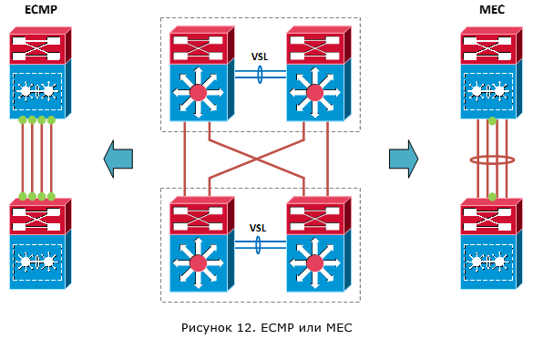
In the first case, the processing of a channel break or failure of an active VSS switch will occur by means of a dynamic routing protocol. In this case, since we will have several equal routes (along the route for each L3 channel), the total bandwidth will be aggregated at the expense of Equal Cost Multipath (ECMP). Actually, ECMP will be responsible for distributing traffic across VSS switches. In the second case, the processing of a channel break or failure of an active VSS switch will be handled by hardware due to the operation of Multichassis EtherChannel. Thanks to the means of balancing traffic between channels (hash functions), MEC will also be responsible for distributing traffic across VSS switches.
Immediately see the advantages of MEC in relation to ECMP. We have fewer logical connections with the neighbor (only one connection), a smaller route table (from one neighbor we accept only one copy of the routes) and less load in case of failure of one of the channels (in fact, it does not exist, because the logical channel even with the loss of one physical will continue to work). Plus, to understand this configuration is more simple.
But what about the switching time? For unicast traffic in both cases this time is the same. But for multicast, no. In the case of multicast traffic, the time of network convergence for ECMP is much longer.
From all this conclusion: it is recommended to use the connection option with one logical connection (MEC).
I would like to briefly touch upon another solution that basically uses VSS technology. This solution is Cisco Catalyst Instant Access. The idea is to get one large virtual switch within the network.
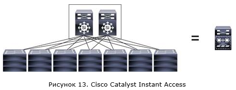
In this case, two 6500E / 6800 switches with Sup2T supervisors and specialized line cards, which are combined using VSS technology, are installed in the core of the network (Instant Access parent). The switches of the access level (Instant Access client) use Cisco switches 6800ia or 3560CX (there can be up to 42). It should be noted that the IA clients switches do not have local switching functions, and absolutely all packets will be transmitted to the kernel switches (IA parent). However, the price of such switches, it seems to me, does not quite correspond to their functionality. But this is a separate conversation.
VSS technology implementation example
Configuring VSS technology is easy. Starting with Cisco IOS XE version 3.6.0E (IOS 15.2 (2) E), you can use a simplified configuration scheme, Easy VSS, to combine two switches into one virtual switch. The two switches are connected to each other and should be visible at the L3 level. Next, we introduce the command to convert to VSS mode on the switch, which we will have the main one:
SwitchA # switch convert mode easy-virtual-switch
Specify the ports that will form the VSL channel (switches should already be connected to each other through these ports):
SwitchA (easy-vss) # VSL Te1 / 1/15 Te1 / 1/16
After that, both switches will reboot to switch to VSS mode. This completes the minimum setting.
If we configure VSS in the classical way, in fact, the scheme is not very complicated. On both switches we configure the following:
After the switches switch to VSS mode, the QoS settings for the VSL channel will be automatically added to the configuration. Additionally (optionally) we can configure the detection of the situation with two active control plane, in the event of a VSL channel rupture. And also set the MAC address of the virtual switch (by default it is set dynamically).
Let's now see what we get after combining switches using the example of the Cisco 4500X:

The first switch has become primary / active (VSS Active, id = 1), and the second one is redundant (VSS Standby, id = 2). The control plane of the first switch became active (Control Plane State = ACTIVE), and the control plane of the second switch became active (Control Plane State = STANDBY), in hot standby mode (Current Software state = STANDBY HOT (switchover target)). To ensure fault tolerance, we use the SSO mechanism (Operating Redundancy Mode = Stateful Switchover). We also see that the data plane on both switches is active (Fabric State = ACTIVE).
The following information shows which ports we use for the VSL channel:

As we see, ports Te1 / 1/15 and Te1 / 1/16 are used under the VSL channel. LMP is running between the switches. Through both ports, using the LMP protocol, we see the second switch (Hello bidir).
At this point, the discussion of the work of Cisco VSS I propose to complete and go to the HPE IRF solution.
SwitchA # switch convert mode easy-virtual-switch
Specify the ports that will form the VSL channel (switches should already be connected to each other through these ports):
SwitchA (easy-vss) # VSL Te1 / 1/15 Te1 / 1/16
After that, both switches will reboot to switch to VSS mode. This completes the minimum setting.
If we configure VSS in the classical way, in fact, the scheme is not very complicated. On both switches we configure the following:
- Virtual Domain (Virtual Switch Domain) and the number of the switch in it:
SwitchA (config) # switch virtual domain 2
SwitchA (config-vs-domain) # switch 1
SwitchB (config) # switch virtual domain 2
SwitchB (config-vs-domain) # switch 2 - VSL Port Channel:
SwitchA (config) # interface port-channel 1
SwitchA (config) # switchport
SwitchA (config-if) # switch virtual link 1
SwitchA (config-if) # no shutdown
SwitchB (config) # interface port-channel 2
SwitchB (config) # switchport
SwitchB (config-if) # switch virtual link 2
SwitchB (config-if) # no shutdown - Add physical ports to the created PortChannel for the VSL channel:
SwitchA (config) # interface range tengigabitethernet 1 / 15-16
SwitchA (config-if) # channel-group 1 mode on
SwitchB (config) # interface range tengigabitethernet 1 / 15-16
SwitchB (config-if) # channel-group 2 mode on - We start conversion on both switches to VSS mode:
SwitchA # switch convert mode virtual
SwitchB # switch convert mode virtual
After the switches switch to VSS mode, the QoS settings for the VSL channel will be automatically added to the configuration. Additionally (optionally) we can configure the detection of the situation with two active control plane, in the event of a VSL channel rupture. And also set the MAC address of the virtual switch (by default it is set dynamically).
Let's now see what we get after combining switches using the example of the Cisco 4500X:
The first switch has become primary / active (VSS Active, id = 1), and the second one is redundant (VSS Standby, id = 2). The control plane of the first switch became active (Control Plane State = ACTIVE), and the control plane of the second switch became active (Control Plane State = STANDBY), in hot standby mode (Current Software state = STANDBY HOT (switchover target)). To ensure fault tolerance, we use the SSO mechanism (Operating Redundancy Mode = Stateful Switchover). We also see that the data plane on both switches is active (Fabric State = ACTIVE).
The following information shows which ports we use for the VSL channel:
As we see, ports Te1 / 1/15 and Te1 / 1/16 are used under the VSL channel. LMP is running between the switches. Through both ports, using the LMP protocol, we see the second switch (Hello bidir).
At this point, the discussion of the work of Cisco VSS I propose to complete and go to the HPE IRF solution.
HP Enterprise IRF
About the HPE IRF solution can be described in less detail than with Cisco VSS. This is due to the fact that the information on this technology is not so much and most often it is rather superficial. Although it may be for the better, you don’t need to “kill” the brain in an attempt to deal with the details. On the other hand, the feeling that you are working with a certain black box does not leave you.
In general, if we are talking about two HPE switches that are stacked (the vendor admits this definition), the work of IRF and VSS is very similar. One of the switches is selected as the master (Master), the second becomes the slave (Slave). Traffic is handled by both switches (i.e. the data plane is active on both devices). The control is exercised by the main switch (it will have an active control plane), while its state is synchronized with the slave.
As a "stack bus" using conventional Ethernet ports. On some models, even 1 Gb / s ports can be used for this, but in most cases ports of at least 10 Gb / s are required. Between the switches, an IRF channel is made (analogous to the VSL channel). All packages add an additional header (IRF tag).

Since the current state of the control plane is synchronized between the switches inside the stack, the failure of the main switch does not stop the traffic. This behavior is similar to the operation of Cisco SSO. Unlike Cisco VSS, synchronization also includes the status of routing protocols. And since the switching takes a rather short time (the vendor claims 50 ms), neighboring devices do not have time to detect the failure of one of the switches and break the L3 connections. Therefore, an analogue technology Cisco NSF is not required.
Like in VSS technology, the IRF stack supports the aggregation of links connected to different stack switches. To ensure the harmonization of the parameters of the logical channel, the LACP protocol is used.
As for the temporary indicator, they look pretty good with IRF technology. For example, the 50 ms indicated above are not the average value, but the maximum. In a number of documents indicated that in fact the switch will happen faster. The same applies to the switching time of traffic flows in the case of adding / deleting physical channels as part of aggregation into one logical one. The value is given - 2 ms. At Cisco, this value is 200 ms. With such temporal indicators, no hash adaptive functions are required.
In the event that the IRF channel is broken and both switches decide to become active, the IRF works using a similar algorithm with Cisco VSS. One of the switches retains its role as the main one, the second switch enters the recovery state (Recovery-state). In this state, it disables all ports except IRF and those ports for which in manual mode indicates that they do not need to be disabled. As soon as the IRF channel is restored, the switch that was in the recovery state will reboot. After the reboot, it will become the slave.
Multi-active detection schemes are also very similar to those we looked at in Cisco VSS. HPE IRF supports the following options:
- LACP MAD (work is similar to Cisco Enhanced PAgP)
- BFP MAD (work similar to Cisco IP BFP)
- ARP MAD (Gratuitous ARP is used, containing the identifier of the active device)
- ND MAD (uses Neighbor Discovery NS packets for IPv6)
HPE recommends using LACP or BFP MAD, since these mechanisms are the fastest. ARP and ND MAD are slower and require the use of STP (which is a little unexpected). By the way, the mechanisms use different logic to select the switch that remains the main (master), so HPE does not recommend using them together (namely, LACP together with the others).
Now let's see how HPE IRF differs from Cisco VSS.
First, IRF technology is supported on a wider model range of switches. In fact, this is the basic stacking technology, which is also available on relatively cheap A3100 switches and on expensive modular 12900s. You can stack switches of only one model range, albeit with a small exception (switches from 5800 and 5820 series and 5900 and 5920 will work together ).
Secondly, IRF technology allows stacking up to nine switches (for some models this value is limited to four). There are two possible connection topologies of switches within the framework of the IRF: bus and ring.
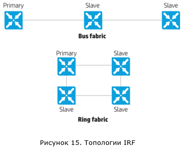
The ring connection option is recommended, as it is more fault tolerant. If one connection is broken, we will not get a situation with two active IRF switch groups.
Judging by the description of the technology, after the switches are combined into an IRF stack, they begin to exchange some kind of hello-packages to build a common stack topology. Further, based on this topology, packets are transmitted within the IRF stack. Unfortunately, more detailed information could not be found.
Before completing the IRF review, it is necessary to say about the development of this technology - enhanced IRF (eIRF). eIRF allows you to build a more hierarchical structure that includes two levels - the core and the access level (Clos architecture is used).

, ( Spine Clos), ( Controlling Bridges — CB). IRF . , ( Leaf Clos), ( Port Extenders – PE). PE ( PEX) . 30 . . Nothing like? , Cisco – Instant Access.
IRF
IRF.
member ID. member ID = 1, member ID :
[Sysname2] irf member 1 renumber 2
Renumbering the member ID may result in configuration change or loss. Continue? [Y/N]:y
[Sysname2] quit
{Sysname2} reboot
, IRF ( ):
[Sysname1] interface range ten-gigabitethernet 1/0/7 to ten-gigabitethernet 1/0/8
[Sysname1-if-range] shutdown
[Sysname2] interface range ten-gigabitethernet 2/0/7 to ten-gigabitethernet 2/0/8
[Sysname2-if-range] shutdown
IRF :
[Sysname1] irf-port 1/1
[Sysname1-irf-port2/1] port group interface ten-gigabitethernet 1/0/7
[Sysname1-irf-port2/1] port group interface ten-gigabitethernet 1/0/8
[Sysname2] irf-port 2/1
[Sysname2-irf-port2/2] port group interface ten-gigabitethernet 2/0/7
[Sysname2-irf-port2/2] port group interface ten-gigabitethernet 2/0/8
, IRF :
[Sysname1] interface range ten-gigabitethernet 1/0/7 to ten-gigabitethernet 1/0/8
[Sysname1-if-range] undo shutdown
[Sysname1-if-range] quit
[Sysname1] save
[Sysname2] interface range ten-gigabitethernet 2/0/7 to ten-gigabitethernet 2/0/8
[Sysname2-if-range] undo shutdown
[Sysname2-if-range] quit
[Sysname2] save
IRF :
[Sysname1] irf-port-configuration active
[Sysname2] irf-port-configuration active
, , . IRF . MAD.
, . (MemberID=1) (Master), (MemberID=2) (Standby).

, IRF :

IRF:

, IRF-Port1 (MemberID=1) IRF-Port2 (MemberID=2).
member ID. member ID = 1, member ID :
[Sysname2] irf member 1 renumber 2
Renumbering the member ID may result in configuration change or loss. Continue? [Y/N]:y
[Sysname2] quit
{Sysname2} reboot
, IRF ( ):
[Sysname1] interface range ten-gigabitethernet 1/0/7 to ten-gigabitethernet 1/0/8
[Sysname1-if-range] shutdown
[Sysname2] interface range ten-gigabitethernet 2/0/7 to ten-gigabitethernet 2/0/8
[Sysname2-if-range] shutdown
IRF :
[Sysname1] irf-port 1/1
[Sysname1-irf-port2/1] port group interface ten-gigabitethernet 1/0/7
[Sysname1-irf-port2/1] port group interface ten-gigabitethernet 1/0/8
[Sysname2] irf-port 2/1
[Sysname2-irf-port2/2] port group interface ten-gigabitethernet 2/0/7
[Sysname2-irf-port2/2] port group interface ten-gigabitethernet 2/0/8
, IRF :
[Sysname1] interface range ten-gigabitethernet 1/0/7 to ten-gigabitethernet 1/0/8
[Sysname1-if-range] undo shutdown
[Sysname1-if-range] quit
[Sysname1] save
[Sysname2] interface range ten-gigabitethernet 2/0/7 to ten-gigabitethernet 2/0/8
[Sysname2-if-range] undo shutdown
[Sysname2-if-range] quit
[Sysname2] save
IRF :
[Sysname1] irf-port-configuration active
[Sysname2] irf-port-configuration active
, , . IRF . MAD.
, . (MemberID=1) (Master), (MemberID=2) (Standby).
, IRF :
IRF:
, IRF-Port1 (MemberID=1) IRF-Port2 (MemberID=2).
, , , , IRF.
Conclusion
, . , « ?» . -, . -, . , IRF . Cisco . VSS . ? And so on. -, , , , , .
| Cisco VSS | HPE IRF | |
|---|---|---|
| Where is supported | 4500X, 4500E, 6500E, 6800 | 3100, 3600, 5120, etc. |
| , | 2 | 9 |
| (SSO/NSF) | Yes | |
| Switching speed in case of failure of the main switch | 200-400 ms | 50 |
| VSL , Ethernet- | IRF channel, Ethernet ports | |
| Situation Detection Technologies with Two Active Switches | ePAgP, Fast Hello, IP BFD | LACP, BFD, ARP, ND |
| Preventing network problems in case of a VSL / IRF channel break | Port blocking | Port blocking |
| Instant access | eIRF |
Bibliography
Cisco VSS
Campus 3.0 Virtual Switching System Design Guide
Release 15.1SY Supervisor Engine 2T Software Configuration Guide, Virtual Switching Systems (VSS)
Release 15.1SY Supervisor Engine 720 Software Configuration Guide, Virtual Switching Systems (VSS)
Catalyst 4500 Series Switch Software Configuration Guide, IOS XE 3.8.0E and IOS 15.2(4)E, Virtual Switching Systems (VSS)
HPE IRF
HP Intelligent Resilient Fabric (IRF) — Frequently Asked Questions
HP 5920 & 5900 Switch Series IRF Configuration Guide
HP FlexFabric 12900 Switch Series IRF Configuration Guide
H3C IRF Technology White Paper
Source: https://habr.com/ru/post/271595/
All Articles