Introduction to AutoCAD Architecture
In the product line from Autodesk, in addition to the basic AutoCAD, there are many specialized products that are optimized for various areas of design. One such product is AutoCAD Architecture. As with AutoCAD, for AutoCAD Architecture it is possible to write plug-ins in .NET. In addition to Autodesk libraries from Autodesk, you can use Teigha for Architecture C ++ library, which allows you to load, draw, and manipulate such objects.
Initially, I wanted to write a series of tutorials that demonstrate working with architectural objects using .NET and Teigha for Architecture, but the introduction to the series of these tutorials has grown into a separate article that is available under the cat.
In the article below there is nothing about programming. It was written in order to give a superficial idea of what AutoCAD Architecture is, what objects it implements and what are their features.
')
AutoCAD Architecture (abbreviation ACA) is a specialized application based on AutoCAD, Autodesk's flagship product, created for the needs of architectural design. The first version of ACA was released in 1998 and has since been updated about once a year. At the moment, the latest version of ACA is called AutoCAD Architecture 2016.
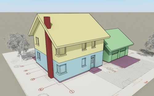
Consider several architectural drawings made with ACA:

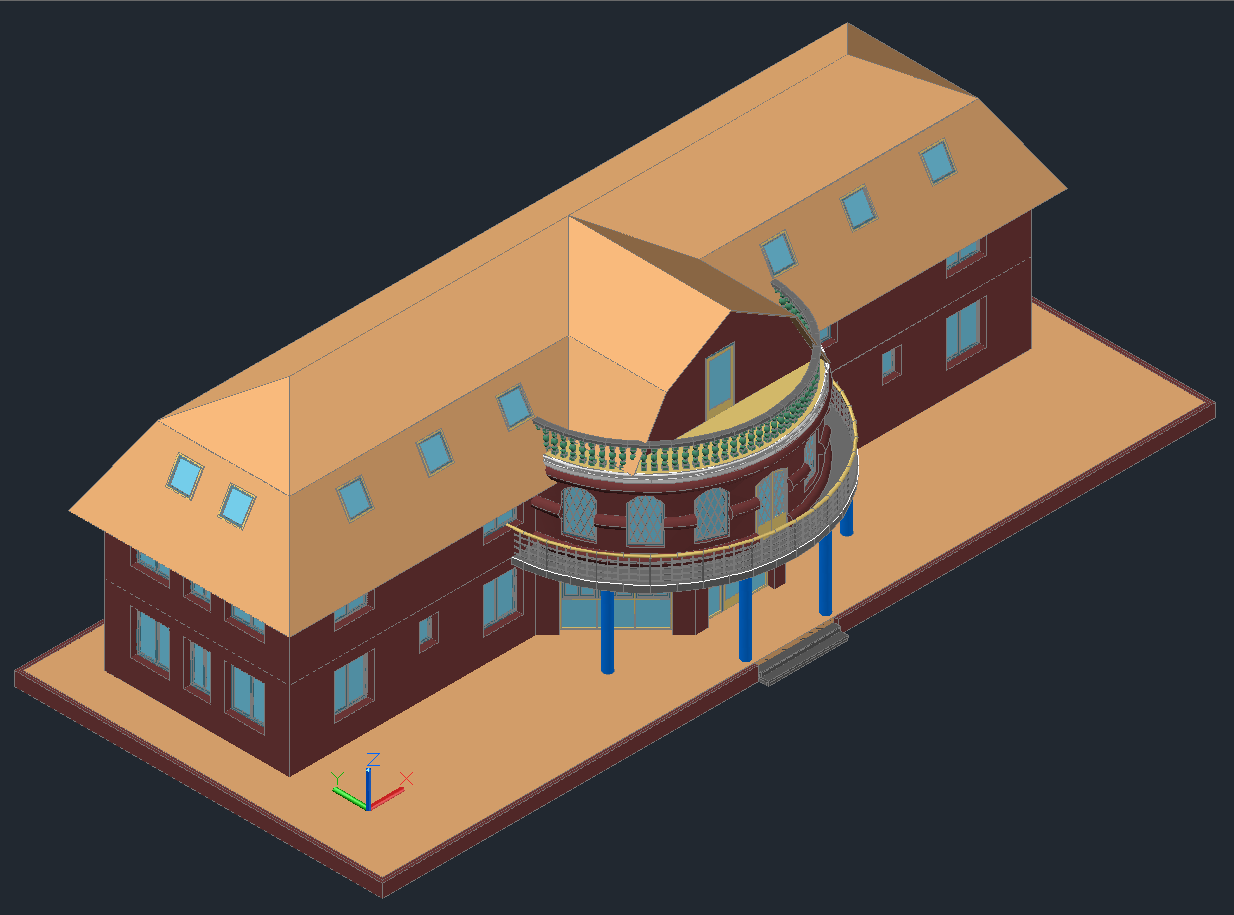
Typically, architectural drawings contain buildings or parts of buildings that consist of parts such as walls, windows, doors, roofs, stairs, etc.
In AutoCAD (the AutoDesk base product), drawing primitives are lines, polylines, blocks, circles, arches, callouts, text, etc. The door to AutoCAD had to be drawn with lines and saved into a separate file (for reuse).
If an object has a different geometry in 2D and 3D views (or even depends on the view direction), then all these options had to be drawn manually and placed in the right one. Looking at the first drawing, we can assume how difficult it is to draw each representation of the object.
In addition, in real-life tasks, drawings are often modified. For example, if on drawing # 1, when using AutoCAD, it became necessary to move the window, then you would need to consistently change both 2D and 3D views.
To move the window on the plan, you need to move the window itself, restore the wall in its place, and on the new - draw an opening. And then do the same for the 3D model. If there are more species, then edits will have to be done in every form. With such changes, it is easy to make mistakes or inconsistencies between species.
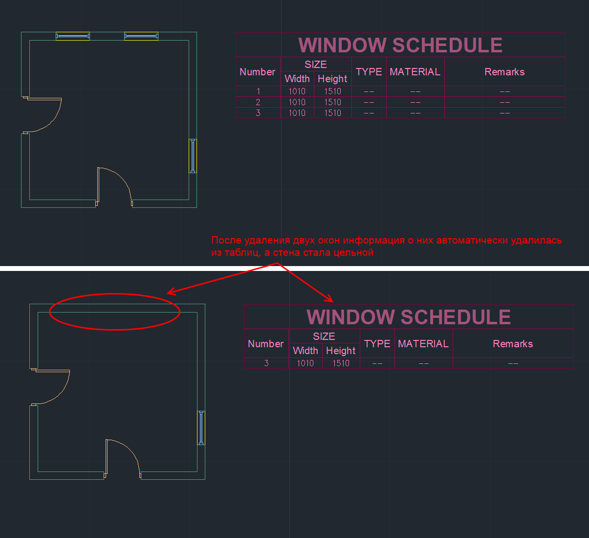
ACA implements special tools and libraries of objects that facilitate and accelerate architectural design. In AutoCAD Architecture, a window and a wall are objects that have connections and behavior. The window “knows” that it is attached to the wall, and the wall knows about the existence of the window. When the window moves, the wall automatically changes its geometry, creating a hole in the new position of the door and removing the hole in the old position. When the wall moves, the door will move along with the wall. If you remove the wall, all the windows and doors that were in this wall will also be deleted:
The drawing model is one. To make a two-dimensional plan view, you only need to switch the view. Editing any view, the entire model is edited:
All sections and floor plans associated with this model are automatically updated when the model is changed, which reduces the possibility of errors and inconsistencies in architectural drawings, and also significantly speeds up their creation.
ACA objects communicate with design documentation. Changes in the drawing automatically change the documentation, thus avoiding errors in it:
In addition to standard AutoCAD primitives, ACA has the following basic primitives (eng):
1) Walls (Walls)
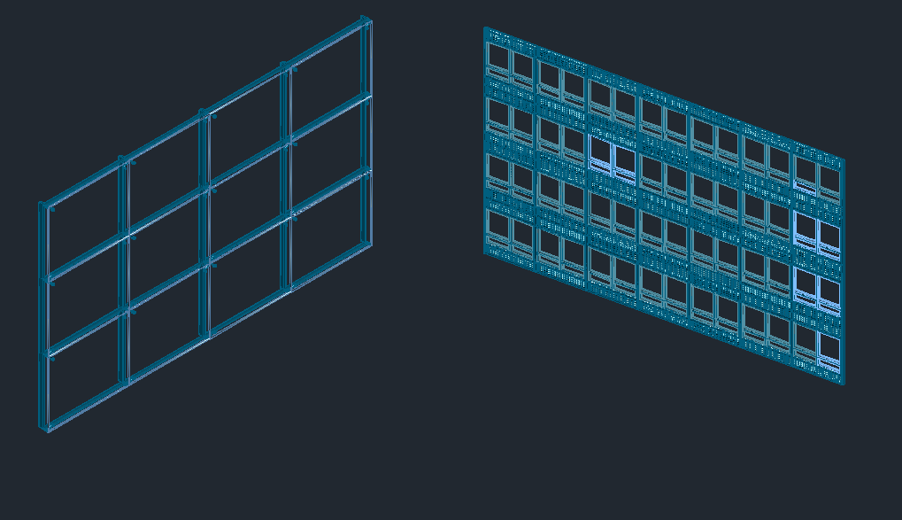
2) Stained glass (Curtain walls). Stained glass windows consist of one or several grids. Each grid in a stained-glass window is divided into cells horizontally or vertically, but the grids can be combined using the nesting method in order to obtain various combinations, from the simplest to the most complex.
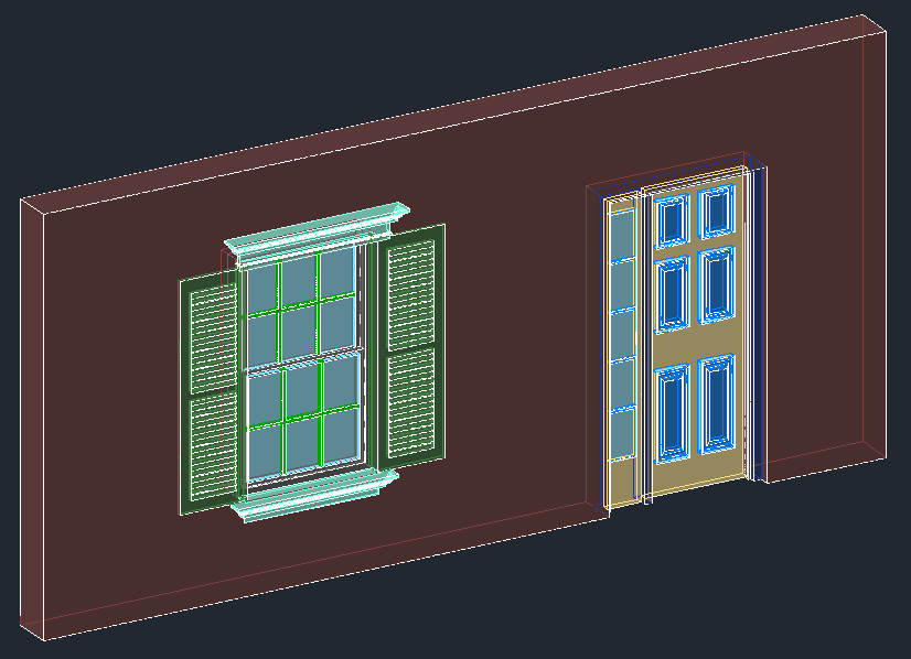
3) Doors, windows, openings, door and window assemblies (Doors, Windows, Openings, DWA):
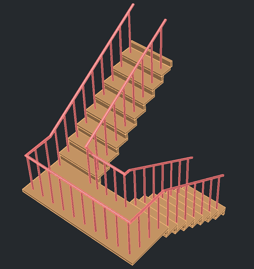
4) Stairs and railings (Stairs and Railings):
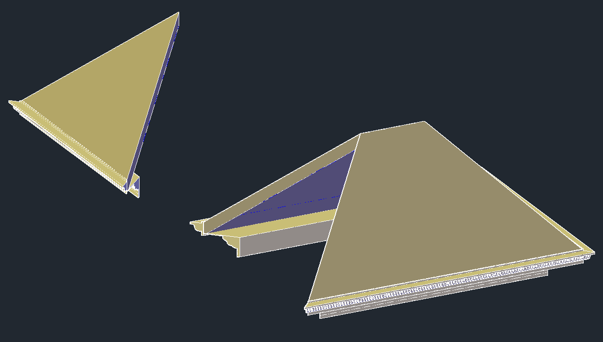
5) Roofs, floors and roofs (Roofs, Slabs and Roof Slabs):
6) Structural Members. A carrier element is an object that can be a beam, brace or column in the drawing. All created beams, braces and columns are subtypes of the same object - the carrier element.

7) Auxiliary primitives: AD-polygons, mass-elements, 2D profiles
ACA objects are AutoCAD custom objects implemented in a group of separate libraries called ACA enablers. To save and load ACA objects, the DWG format is used, but these libraries are required to display and work with such objects.
In essence, an ACA object is a C ++ class. The object's geometry is calculated during drawing and depends on its settings (and not specified in advance).
For example, in the screenshot below you can see some parameters of the doors in the dialog box: width, height, height, alignment, style, and so on. The doors in the screenshot differ only in width and opening angle, but on the basis of these data, the difference in geometry turned out to be significant.

Without going into relationships and details, consider the main features related to ACA objects:
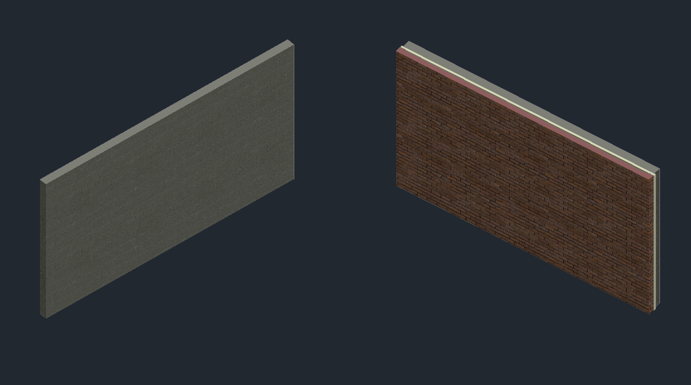
1. ACA objects are assigned a style that defines appearance (and partly behavior).
2. ACA objects viewport dependent. They draw a different view of themselves in different views. Submission refers to geometry. For example, an isometric wall is usually depicted as a 3D model, and in a top view, as a rectangle.
3. The geometry of ACA objects consists of individual components. Each object representation has its own set of components.
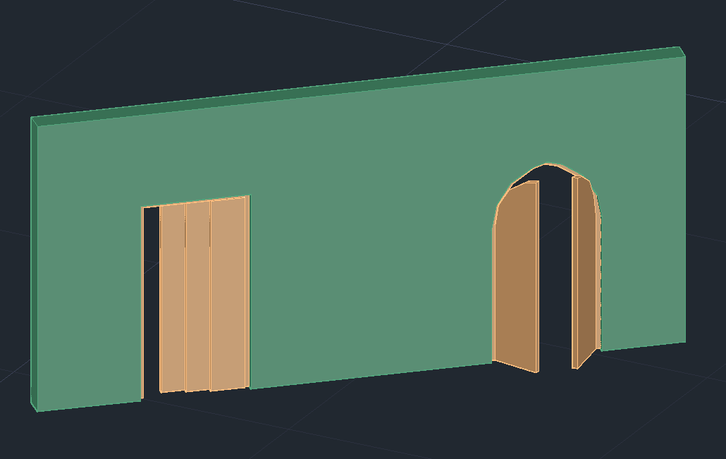
For example, two doors are shown below. They behave like doors in the sense that they can be inserted into the wall, added to the documentation, they will also move as the wall moves. But they look different, because they are assigned a different style.
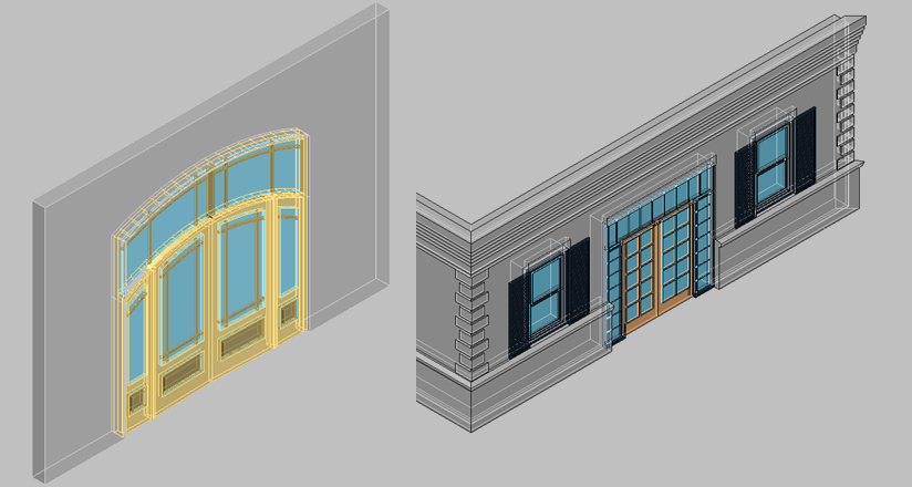
Object styles can be very complex. For example, below - these are also doors (and windows).
The style must be created only once, and then you can add any number of doors of this style. Changing the style will change all the doors that have this style.
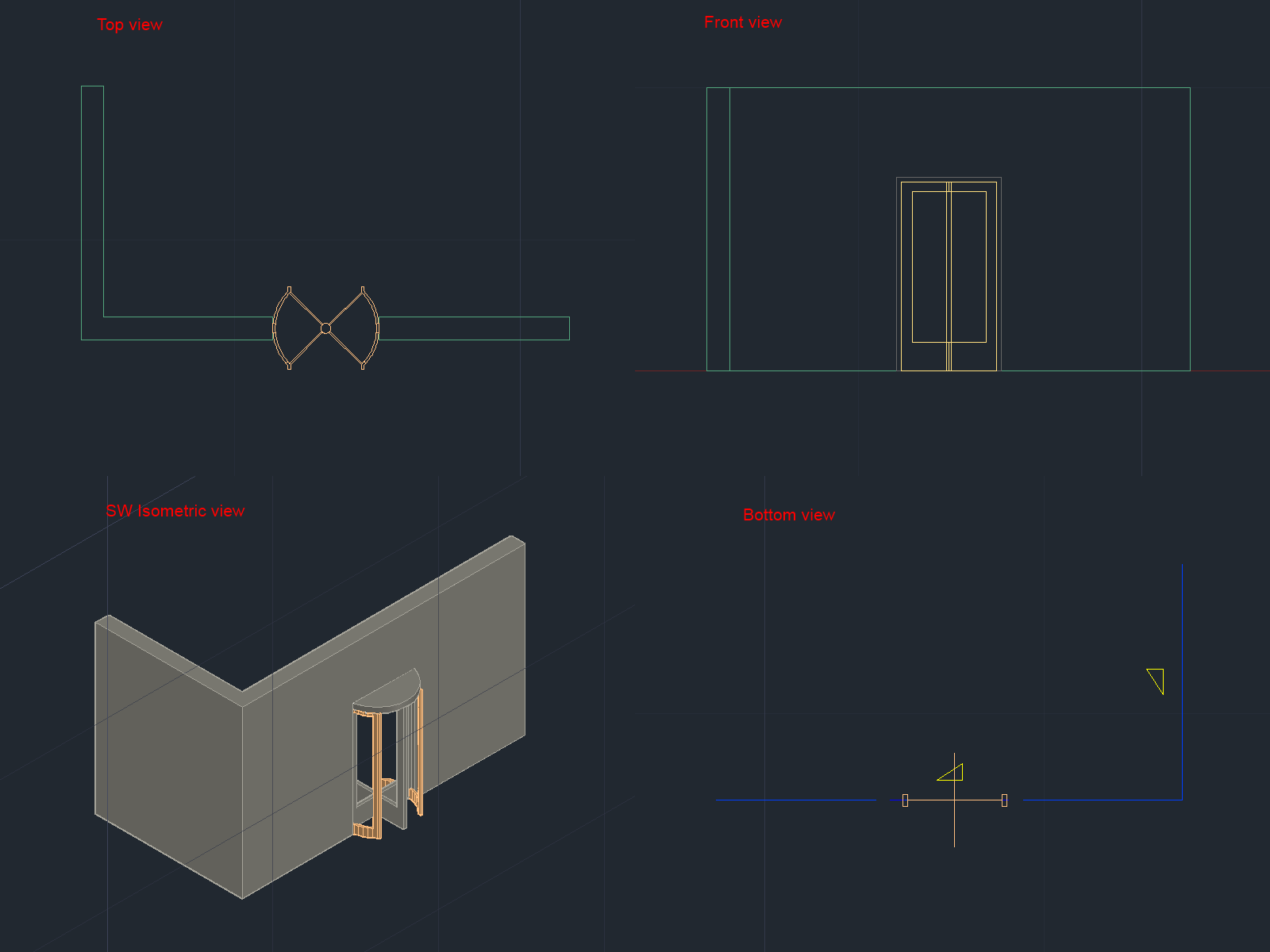
The figure below shows the same model. Only the view changes - the direction in which the camera “looks” at the object. Depending on the settings and camera direction, ACA objects draw different geometries. The geometry of the object in each twist reflects the logic of this view and is not related to the geometry in the other views.
In AutoCAD, you had to draw each presentation manually. Moreover, if there are several types of doors in a building, then each of them had to be drawn for all use cases.
The ACA libraries of architectural objects already contain a large selection of pre-made styles. For example, the drawing below shows some types of doors with styles from the library:

The geometry of an ACA object consists of several separate components. Geometry is usually divided into components in accordance with the logic of the physical world. So the window components may have a frame, glass, sash, and so on.
For example, consider the door in 3D. In the open list you can see the components that make up the painted door. Each component can change its properties (color, type of lines, etc.), as well as show or make it invisible.
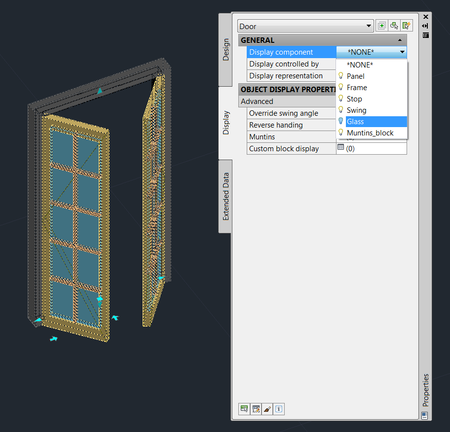
In different representations, the object has different components. The door to top view (plan representation) has a different geometry and, accordingly, a different set of components of which it consists.

The following "primitives" exist for creating documentation in the ASA:
• 2d sections
• Dimensions
• Schedule tables
• Spaces
Documentation objects are also designed to work with architectural objects and have additional logic. For example, consider the dimension lines (dimensions):

When working with ACA-dimensions, there is no need to manually draw the dimensions of each object. When we attach a dimension object to the wall, the dimensions of the windows, doors and openings will be automatically entered. As the openings move, the dimension lines will automatically redraw to reflect the current state of the drawing. If we move the wall, the dimension lines will automatically move behind the wall. When deleting objects, parts of the dimension lines that belonged to these objects are also deleted.
Above, I tried to give a superficial idea of the ACA and the objects that are “primitives” in it. Working with an architectural drawing in ACA is that we draw a building not with low-level AutoCAD primitives (lines, circles, arches, etc.), but with the help of higher-level primitives, such as walls, windows, doors, roofs. When the model is created, based on it, you can automatically generate documentation, 2D projections, floor plans, sections. Having the behavior of objects facilitates the task of further modification of the drawing and allows you to keep the documentation up to date.
Initially, I wanted to write a series of tutorials that demonstrate working with architectural objects using .NET and Teigha for Architecture, but the introduction to the series of these tutorials has grown into a separate article that is available under the cat.
In the article below there is nothing about programming. It was written in order to give a superficial idea of what AutoCAD Architecture is, what objects it implements and what are their features.
')
Introduction
AutoCAD Architecture (abbreviation ACA) is a specialized application based on AutoCAD, Autodesk's flagship product, created for the needs of architectural design. The first version of ACA was released in 1998 and has since been updated about once a year. At the moment, the latest version of ACA is called AutoCAD Architecture 2016.
Why did it become necessary to create such a product?
Consider several architectural drawings made with ACA:
Typically, architectural drawings contain buildings or parts of buildings that consist of parts such as walls, windows, doors, roofs, stairs, etc.
In AutoCAD (the AutoDesk base product), drawing primitives are lines, polylines, blocks, circles, arches, callouts, text, etc. The door to AutoCAD had to be drawn with lines and saved into a separate file (for reuse).
If an object has a different geometry in 2D and 3D views (or even depends on the view direction), then all these options had to be drawn manually and placed in the right one. Looking at the first drawing, we can assume how difficult it is to draw each representation of the object.
In addition, in real-life tasks, drawings are often modified. For example, if on drawing # 1, when using AutoCAD, it became necessary to move the window, then you would need to consistently change both 2D and 3D views.
To move the window on the plan, you need to move the window itself, restore the wall in its place, and on the new - draw an opening. And then do the same for the 3D model. If there are more species, then edits will have to be done in every form. With such changes, it is easy to make mistakes or inconsistencies between species.
ACA implements special tools and libraries of objects that facilitate and accelerate architectural design. In AutoCAD Architecture, a window and a wall are objects that have connections and behavior. The window “knows” that it is attached to the wall, and the wall knows about the existence of the window. When the window moves, the wall automatically changes its geometry, creating a hole in the new position of the door and removing the hole in the old position. When the wall moves, the door will move along with the wall. If you remove the wall, all the windows and doors that were in this wall will also be deleted:
The drawing model is one. To make a two-dimensional plan view, you only need to switch the view. Editing any view, the entire model is edited:
All sections and floor plans associated with this model are automatically updated when the model is changed, which reduces the possibility of errors and inconsistencies in architectural drawings, and also significantly speeds up their creation.
ACA objects communicate with design documentation. Changes in the drawing automatically change the documentation, thus avoiding errors in it:
Types of primitives in ACA
In addition to standard AutoCAD primitives, ACA has the following basic primitives (eng):
1) Walls (Walls)
2) Stained glass (Curtain walls). Stained glass windows consist of one or several grids. Each grid in a stained-glass window is divided into cells horizontally or vertically, but the grids can be combined using the nesting method in order to obtain various combinations, from the simplest to the most complex.
3) Doors, windows, openings, door and window assemblies (Doors, Windows, Openings, DWA):
4) Stairs and railings (Stairs and Railings):
5) Roofs, floors and roofs (Roofs, Slabs and Roof Slabs):
6) Structural Members. A carrier element is an object that can be a beam, brace or column in the drawing. All created beams, braces and columns are subtypes of the same object - the carrier element.
7) Auxiliary primitives: AD-polygons, mass-elements, 2D profiles
What are ACA primitives?
ACA objects are AutoCAD custom objects implemented in a group of separate libraries called ACA enablers. To save and load ACA objects, the DWG format is used, but these libraries are required to display and work with such objects.
In essence, an ACA object is a C ++ class. The object's geometry is calculated during drawing and depends on its settings (and not specified in advance).
For example, in the screenshot below you can see some parameters of the doors in the dialog box: width, height, height, alignment, style, and so on. The doors in the screenshot differ only in width and opening angle, but on the basis of these data, the difference in geometry turned out to be significant.
Main features of ACA facilities
Without going into relationships and details, consider the main features related to ACA objects:
1. ACA objects are assigned a style that defines appearance (and partly behavior).
2. ACA objects viewport dependent. They draw a different view of themselves in different views. Submission refers to geometry. For example, an isometric wall is usually depicted as a 3D model, and in a top view, as a rectangle.
3. The geometry of ACA objects consists of individual components. Each object representation has its own set of components.
ACA objects are assigned a style that defines the appearance of the object.
For example, two doors are shown below. They behave like doors in the sense that they can be inserted into the wall, added to the documentation, they will also move as the wall moves. But they look different, because they are assigned a different style.
Object styles can be very complex. For example, below - these are also doors (and windows).
The style must be created only once, and then you can add any number of doors of this style. Changing the style will change all the doors that have this style.
The geometry of ACA objects depends on the view.
The figure below shows the same model. Only the view changes - the direction in which the camera “looks” at the object. Depending on the settings and camera direction, ACA objects draw different geometries. The geometry of the object in each twist reflects the logic of this view and is not related to the geometry in the other views.
In AutoCAD, you had to draw each presentation manually. Moreover, if there are several types of doors in a building, then each of them had to be drawn for all use cases.
The ACA libraries of architectural objects already contain a large selection of pre-made styles. For example, the drawing below shows some types of doors with styles from the library:
The geometry of ACA objects consists of components.
The geometry of an ACA object consists of several separate components. Geometry is usually divided into components in accordance with the logic of the physical world. So the window components may have a frame, glass, sash, and so on.
For example, consider the door in 3D. In the open list you can see the components that make up the painted door. Each component can change its properties (color, type of lines, etc.), as well as show or make it invisible.
In different representations, the object has different components. The door to top view (plan representation) has a different geometry and, accordingly, a different set of components of which it consists.
Documentation Objects
The following "primitives" exist for creating documentation in the ASA:
• 2d sections
• Dimensions
• Schedule tables
• Spaces
Documentation objects are also designed to work with architectural objects and have additional logic. For example, consider the dimension lines (dimensions):
When working with ACA-dimensions, there is no need to manually draw the dimensions of each object. When we attach a dimension object to the wall, the dimensions of the windows, doors and openings will be automatically entered. As the openings move, the dimension lines will automatically redraw to reflect the current state of the drawing. If we move the wall, the dimension lines will automatically move behind the wall. When deleting objects, parts of the dimension lines that belonged to these objects are also deleted.
Conclusion
Above, I tried to give a superficial idea of the ACA and the objects that are “primitives” in it. Working with an architectural drawing in ACA is that we draw a building not with low-level AutoCAD primitives (lines, circles, arches, etc.), but with the help of higher-level primitives, such as walls, windows, doors, roofs. When the model is created, based on it, you can automatically generate documentation, 2D projections, floor plans, sections. Having the behavior of objects facilitates the task of further modification of the drawing and allows you to keep the documentation up to date.
Source: https://habr.com/ru/post/271571/
All Articles