We are switching from STM32 to the Russian K1986BE92QI microcontroller. Practical application: control LED brightness (PWM)
Introduction
In the two previous articles, we generated a clock signal of the frequency we need with the help of PWM, receiving equal intervals of luminescence and its absence on the LED. This task takes place in practice (in one of the subsequent articles we will definitely encounter it). But most often PWM is used for another purpose. One of the most common - control the brightness of the LEDs or the speed of rotation of the motors. Also with the help of PWM you can generate sound (what the next article will be about). And in this article I would like to tell you how you can control the brightness of the LED on our controller.
Let's start: changing the settings of the main timer
We will take the project from this article as a basis. Based on the initTimerPWMled function, we will create the initTimerPWMconstPeriod function. The parameter of the function will not be PWM_speed (PWM frequency), but timeEnabledState will be the duration of the pulse. The theory of voltage generation at the output by the PWM method is perfectly described by this short article. To begin with, we will define the parameters:
- Let the duration of the whole period of the function be 0xFFFF ticks of the timer (you can choose any value, I chose this value for convenience and not to change the code for the next article on generating PWM sound)
- Then the parameter of the timeEnabledState function will show how many clock cycles from 0xFFFF on the output is "1". All the rest of the time on channel "0". For example, if timeEnabledState = 0x4000, the signal will look like this.
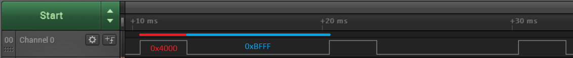
')
At 0x8000 will be almost equal.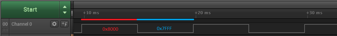
Well, at 0xF000, the signal "1" will almost always be.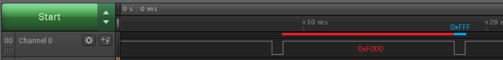
The shorter the period, the better. We have chosen a period of 0xFFFF cycles. To achieve good results, we need to maximize the frequency of these periods. To do this, turn off the clock divider in the initTimerPWMconstPeriod function.
MDR_TIMER1->PSG = 0; // . MDR_TIMER1->ARR = 0xFFFF; // . 0 0xFFFF. MDR_TIMER1->CCR1 = timeEnabledState; // 1 0 - . MDR_TIMER1->CH1_CNTRL = 6<<TIMER_CH_CNTRL_OCCM_Pos; // REF = 1, CNT < CCR1, 0 - CNT >= CCR1; In fact, at this stage we have already obtained the function that sets the PWM signal's duty cycle. But you need to take care that when changing the value of CCR1 the counter does not go beyond the limits. To do this, set the CRRRLD bit in the CH1_CNTRL2 register. It allows changing the value of CCR1 and CCR2 only with CNT == 0.
MDR_TIMER1->CH1_CNTRL2 = TIMER_CH_CNTRL2_CCRRLD; // CCR1 CNT = 0. . Finish: change interrupt settings
With the PWM setting, we figured it out. It remains only to slightly change the interrupt by polling keys. Let us set a new variable characterizing the pulse duration in the period. Let's call it PWM_time . By default, let it be 0xFFFF (PWM is not at this value, the LED is on). And then we'll see at what interval to take a step when pressing the key. To do this, we decompose the number of cycles of the period into prime factors.
// 65535 = 3·5·17·257. 257 0 - 257 - . => 3*5*17 = 255. From the calculation we see that walking with an interval of 255, we can go through the whole scale from 0 to 257. So we proceed. We get the following code. // 65535 = 3·5·17·257. 257 0 - 257 - . => 3*5*17 = 255. if (UP_FLAG == 0) PWM_time+=255; // , - . - - . else if (DOWN_FLAG == 0) PWM_time-=255; else if (LEFT_FLAG == 0) PWM_time-=255; else if (RIGHT_FLAG == 0) PWM_time+=255; if (PWM_time < 0) PWM_time = 0; // , "" . else if (PWM_time > 0xFFFF) PWM_time = 0xFFFF; It remains only to assign a new value. MDR_TIMER1->CCR1 = PWM_time; // . I will note once again that we don’t touch the period. He is permanent. We change only the pulse duration. The whole interruption will be as follows. int PWM_time = 0xFFFF; // . void Timer2_IRQHandler (void) { MDR_TIMER2->STATUS = 0; // . . //LED1_FLAG = !LED1_FLAG; // , . // 65535 = 3·5·17·257. 257 0 - 257 - . => 3*5*17 = 255. if (UP_FLAG == 0) PWM_time+=255; // , - . - - . else if (DOWN_FLAG == 0) PWM_time-=255; else if (LEFT_FLAG == 0) PWM_time-=255; else if (RIGHT_FLAG == 0) PWM_time+=255; if (PWM_time < 0) PWM_time = 0; // , "" . else if (PWM_time > 0xFFFF) PWM_time = 0xFFFF; MDR_TIMER1->CCR1 = PWM_time; // . } I deliberately hid an LED inversion string indicating that an interrupt is occurring. Because there is not enough current for 2 LEDs and unwanted ripples appear.Conclusion
In this article, we looked at how you can configure and control PWM. In the next article, we will try to generate a sound using PWM.
Project files to the article.
List of previous articles.
- We turn from STM32F103 to K1986BE92QI. Or the first acquaintance with the Russian microcontroller.
- We are switching from STM32 to the Russian K1986BE92QI microcontroller. Setup project in keil and flashing LED.
- We are switching from STM32 to the Russian K1986BE92QI microcontroller. System Timer (SysTick).
- We are switching from STM32 to the Russian K1986BE92QI microcontroller. Setting the clock frequency.
- We are switching from STM32 to the Russian K1986BE92QI microcontroller. Practical application: Generate and reproduce sound. Part one: we generate a square and sinusoidal signal. Mastering the DAC (DAC).
- We are switching from STM32 to the Russian K1986BE92QI microcontroller. Practical application: Generate and reproduce sound. Part two: generate a sinusoidal signal. Mastering DMA.
- We are switching from STM32 to the Russian K1986BE92QI microcontroller. Practical application: Generate and reproduce sound. Part three: generate a sine wave. A simple look at DMA + first acquaintance with timers.
- We are switching from STM32 to the Russian K1986BE92QI microcontroller. Practical application: Generate and reproduce sound. Part Four: we create the digital part of a single-voiced and multi-voiced musical postcard.
- We are switching from STM32 to the Russian K1986BE92QI microcontroller. Practical application: We interrogate keys, we generate PWM. Comparison of CMSIS and SPL code (PWM + TIM + PORT). Part one.
- We are switching from STM32 to the Russian K1986BE92QI microcontroller. Practical application: We interrogate keys, we generate PWM. Comparison of CMSIS and SPL code (PWM + TIM + PORT). Part two.
Source: https://habr.com/ru/post/270887/
All Articles