Automatic generation of microcontroller software code based on event-oriented model
Task setting :
Creating a complex automated system based on the controller to control various peripherals (electronic locks, motors, LED strips and other electronics).
Creating this system was required for a quest room like this , but in the city of Khabarovsk .
Our quest is in a different setting , but in general has approximately the same set of actuators: relays, locks, tapes, reed switches, etc.
Basic system requirements:
Our quest required a rather complicated scenario, in particular:

')
The solution to all the problems was found largely due to the article on the “Paradigm of situation-oriented programming” , applying this approach I get out of the box:
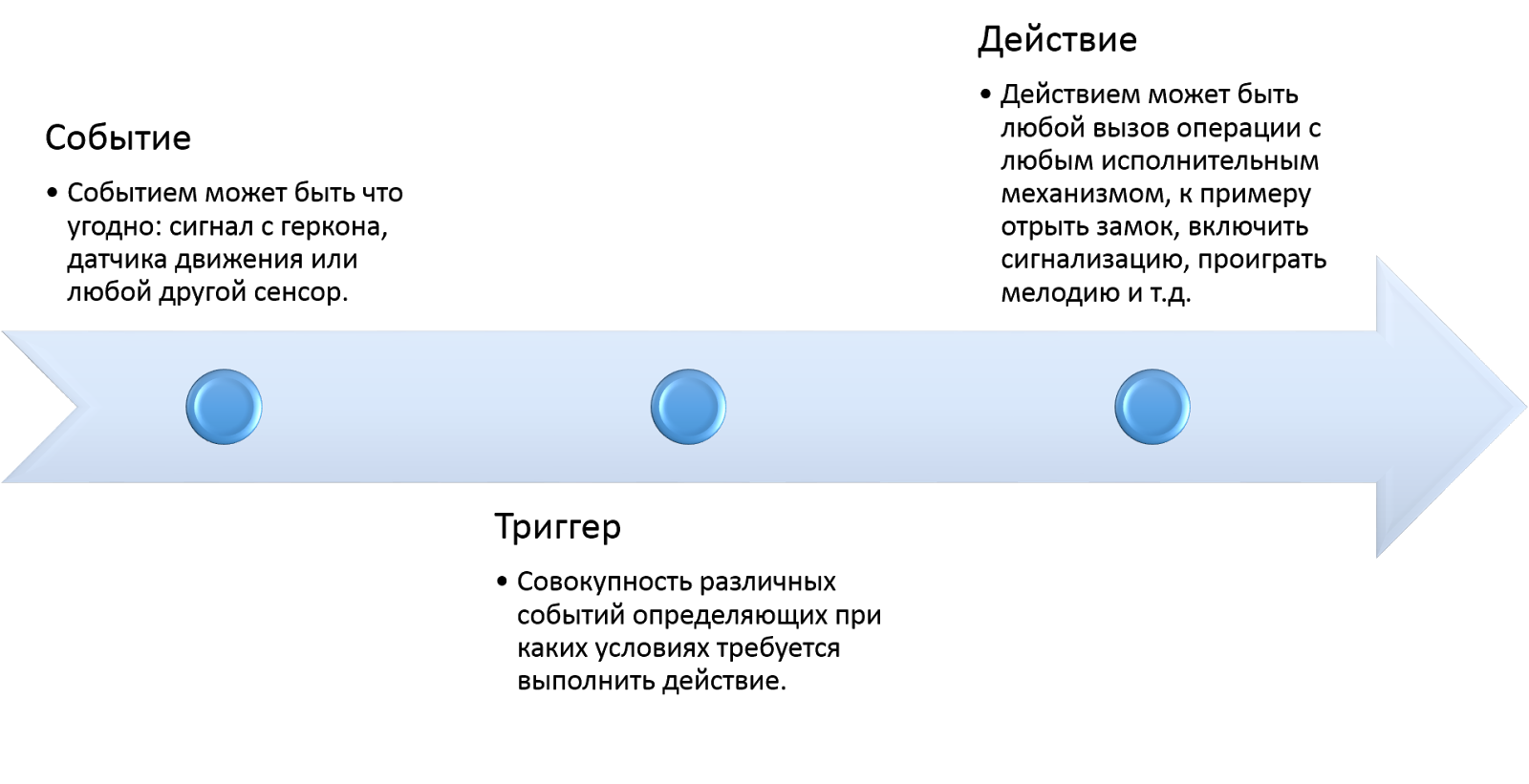
Thus, the system architecture can be built on the basis of 3 types of basic structures:
With this architecture, you can also notice that if you specify the state saving condition (activated / not activated) in the trigger code template, you get the opportunity to use the trigger state as an event as a bonus, so you can build an arbitrarily complex system of event interconnections and nonlinearity of the algorithm .
Due to the allocation of actions into a separate functional unit, we can, even at the development stage, test the program code of each action separately, debugging such code is much easier than when debugging the entire project. Triggers will already be referenced to the debugged code.

Triggers as a trigger condition can use any combination of events or trigger states (and \ or \ not).
Events can be any (state of ports, messages in serial and so on), in the current implementation, the state of ports was sufficient, so while only this option is left, the functionality extensions will not take much time.
When creating the system, it was decided to use equipment available on the local market, only Arduino boards turned out to be such, given the problems with delivery of mail from other regions, the fact that there are spare parts on the market matters.
The application is configured to generate a sketch code for this platform, but if desired, adaptation for any other programming language will take only a couple of minutes.
Thus, the templates for the Arduino sketch will look as simple as:
Based on the template data, all script parameters can be set in the application window.

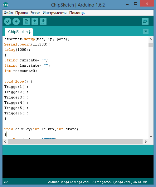
After exporting the firmware, we can get a similar code:
The advantage of this approach is that all the action blocks at the time of exporting the firmware are already debugged at the development stage, all the trigger blocks, sensors and action code wrappers are debugged and the code is compiled without errors and will work correctly right away , without a debugging step .
In practice, when developing a quest room, you had to change the script many times, thanks to the application, you did not need to change the firmware code , it is enough to change the parameters of the triggers in the program interface .
Photos from the quest do not attach yet, if I can, I can attach the desire. At the moment, the equipment with the firmware created by this scheme has already completed more than 50 game cycles without a single failure.
The source code of the application is open and available to everyone .
A test application with typical template settings can be found on github .
I hope this article will help those who decide to create a system to automate various processes, be it a smart home, a security system, or anything else.
Creating a complex automated system based on the controller to control various peripherals (electronic locks, motors, LED strips and other electronics).
Creating this system was required for a quest room like this , but in the city of Khabarovsk .
Our quest is in a different setting , but in general has approximately the same set of actuators: relays, locks, tapes, reed switches, etc.
Basic system requirements:
- Reliability - when developing complex systems, there is a high probability to make difficult errors, the more the code, the greater the chance to miss the error and the more time it takes to debug, it is necessary to minimize the probability of incorrect operation.
- Flexibility - the ability to change the logic of work with minimal time costs
- Functionality - control of any equipment and connection of any sensors.
Our quest required a rather complicated scenario, in particular:
- The nonlinearity of the storyline - players can find several different ways to solve puzzles,
- Connectedness - some events should occur only after the completion of a number of other game events
')
The solution to all the problems was found largely due to the article on the “Paradigm of situation-oriented programming” , applying this approach I get out of the box:
- Flexibility - it's enough to build an event architecture.
- Reliability - because all events are of the same type they can be implemented in a similar way, using simple code whose reliability can be guaranteed
- Functionality - events trigger actions that can be implemented in any way.
Thus, the system architecture can be built on the basis of 3 types of basic structures:
- Event
- Trigger
- Act
With this architecture, you can also notice that if you specify the state saving condition (activated / not activated) in the trigger code template, you get the opportunity to use the trigger state as an event as a bonus, so you can build an arbitrarily complex system of event interconnections and nonlinearity of the algorithm .
Due to the allocation of actions into a separate functional unit, we can, even at the development stage, test the program code of each action separately, debugging such code is much easier than when debugging the entire project. Triggers will already be referenced to the debugged code.
Triggers as a trigger condition can use any combination of events or trigger states (and \ or \ not).
Events can be any (state of ports, messages in serial and so on), in the current implementation, the state of ports was sufficient, so while only this option is left, the functionality extensions will not take much time.
When creating the system, it was decided to use equipment available on the local market, only Arduino boards turned out to be such, given the problems with delivery of mail from other regions, the fact that there are spare parts on the market matters.
The application is configured to generate a sketch code for this platform, but if desired, adaptation for any other programming language will take only a couple of minutes.
Thus, the templates for the Arduino sketch will look as simple as:
Main program code
@init void setup() { @runonce } void loop() { @loopcode } @triggers @sensors @actions Action code template
//@description void @name() { bool debug=true; //@id @code //@id if (debug) { Serial.println("DoAction @name"); } } Trigger Code Template
//@description bool @nameActivated=false; bool @name(){ if (@nameActivated){ return true; }else { if (@event){ @nameActivated=true; Serial.println("@name Activated"); @nameDoAction(); return true; } return false; } return false; } void @nameDoAction(){ @nameActivated=true; //****************************************** @actions //****************************************** } Sensor Code Template
//@description bool @name() { int @namePin=@pinNumber; pinMode(@namePin, INPUT_PULLUP); int sensorVal = digitalRead(@namePin); if (sensorVal == @trueval) {return true;}else{return false;} } Sample Initialization Template
In this template, you can connect libraries and declare variables and functions global for the whole project.
#include <etherShield.h> #include <ETHER_28J60.h> #include <EEPROM.h> static uint8_t mac[6] = {0x54, 0x55, 0x58, 0x10, 0x10, 0x24}; static uint8_t ip[4] = {192, 168, 137, 15}; static uint16_t port = 80; ETHER_28J60 ethernet; bool started=false; Based on the template data, all script parameters can be set in the application window.
After exporting the firmware, we can get a similar code:
A lot of letters of the sketch
The advantage of this approach is that all the action blocks at the time of exporting the firmware are already debugged at the development stage, all the trigger blocks, sensors and action code wrappers are debugged and the code is compiled without errors and will work correctly right away , without a debugging step .
In practice, when developing a quest room, you had to change the script many times, thanks to the application, you did not need to change the firmware code , it is enough to change the parameters of the triggers in the program interface .
Photos from the quest do not attach yet, if I can, I can attach the desire. At the moment, the equipment with the firmware created by this scheme has already completed more than 50 game cycles without a single failure.
The source code of the application is open and available to everyone .
A test application with typical template settings can be found on github .
I hope this article will help those who decide to create a system to automate various processes, be it a smart home, a security system, or anything else.
Source: https://habr.com/ru/post/269897/
All Articles