Multiklet became more accessible
Three years ago the first multicellular processor was born. At that time, it was a really pleasant event for us that the processor started working on the first attempt to implement a new architecture in silicon. For the Multiklet P1 processor, two debug boards were developed, which allowed to master the processor and had the basic elements of the periphery in their composition.
Two years have passed and a replenishment occurred in a multicellular family, and the world saw R1 Multiklet. In this article, we will take a detailed look at the debug kit for the first processor with cell reconfiguration, and also demonstrate the most budgetary version of the debug board.

Figure 1. Sketch processor board
')
1. Expectations and results
Since this article is intended to review the debugging complex, but there may be questions about the processor, so I prepared a list of my publications on processors.
Before developing a new debugging board, competitors were analyzed, and a discussion was held in various forums on what the debugging board should be. As a result, in connection with the expansion of the processor line, so that everyone had enough space in the house and in order to reduce the cost of manufacturing the processor board, it was decided to have a modular structure of the debugging system.
Figures 1 and 2 show thumbnails of the debug board, i.e. what we wanted to get 2 years ago and what we came up with in our community. We express our gratitude to all who shared their advice and participated in the creation of the concept of a new board.
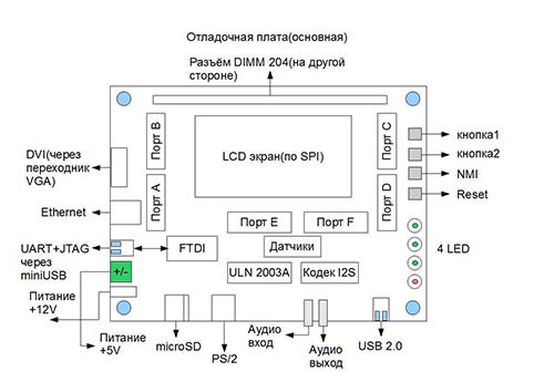
Figure 2. Sketch baseboard
Development of the debug board was entrusted to professionals from LDM-Systems. Of course, we assumed that it would end up because This company has already made a debug board for us for the P1 Multiclet processor. But the result exceeded all our expectations.
A debugging kit was developed, consisting of a base universal board and a processor board connected to it, see Fig.3.
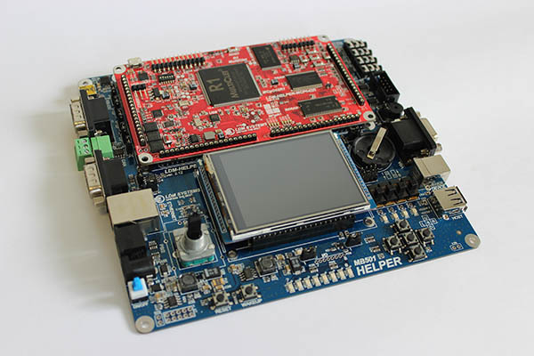
Figure 3. Full debug kit
The R1 processor started up the first time and blinked with LEDs. Of course, to make such a fairly voluminous thing was ideally difficult. But it was from what to make a start and without any problems we came to the debugging version, which I like, and I hope, will satisfy the needs of most of our users. It is worth noting that at some point it was necessary to re-dissolve a lot of lines on the board (once again, I insisted on this, so it was partly my fault that the first users had a slightly delayed delivery date) so that everything would be aesthetic and convenient for users with all the peripheral blocks, as they say "meet on clothes." For which we are very grateful to our masters from LDM-Systems, who built a cozy control point for the Multiklet R1.
2. Overview of the debugging kit
Today, we continue to develop to the best of our abilities, and if we abstract to automotive topics, our model range has replenished and currently includes three types of cars.
The first type is a debugging set consisting of the MB501 baseboard, containing the full set of necessary interfaces, a processor board and the necessary connectors and wires, see Figure 4.
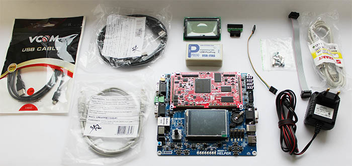
Figure 4. Maximum grade baseboard
The second type is distinguished by a baseboard, called pMB101, which has a somewhat trimmed set of connectors on board, but allows you to use all the necessary interfaces and assemble your device as a compact, ready-made module, see Figure 5.
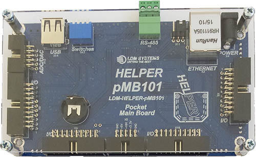

Figure 5. Compact Baseboard Version
The third type also has a difference in the baseboard version, which is called the uMB301 and allows you to join the processor board in the most compact form, see Figure 6.

Figure 6. Micro Baseboard Version
Thus, we got a complete set of sedan, hatchback and coupe. Figure 7 shows with which main interfaces it is possible to work on the baseboard, although there are also SPI, I2C, I2S and other interfaces that can be used through the pins on the processor or baseplate.
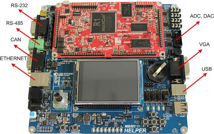
Figure 7. Basic Baseboard Interfaces
We also prepared a video demonstration of the debugging board:
But alternatives are possible to control the multicellular processor, more on this later.
3. Minimum grade
As in the automotive industry, according to numerous requests was issued a minimum set of debug kit. But almost every car bought in the minimum configuration, you can then bring to the configuration "Suite" and buy winter tires. We decided not to depart from this concept and as a result we removed some of the elements of the processor board, as well as the protective housing of the programmer. We did not act as radically as in the Martian film and with our module we dropped only some peripheral components, which allowed us to reduce the cost of producing a processor board from Multiclet R1, taking into account the programmer in the set, to the level of the previous generation debugging board from Multiclet P1.
It turned out the minimum configuration of the processor board, see figure 8.

Figure 8. Processor board with a reduced number of elements
Some components for the operation of the periphery and their binding were not installed on the processor board, in fig. 9 demonstrated these elements.
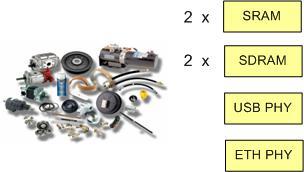
Figure 9. Basic elements that were not installed on the board.
Thus, the main non-installed components were 2 SRAM memory, 2 SDRAM memory, physical layer chips for USB, ETHERNET. You can bring the processor board to the maximum configuration. To do this, simply contact your authorized dealer or any soldering services salon. For components, you also have the right to decide which ones to install, original or not.
The minimum configuration also includes a programmer without a case (see Fig. 10) and a microUSB USB cable for power supply from the USB port.
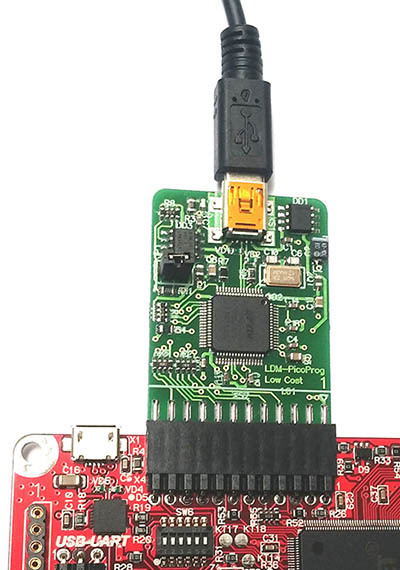
Figure 10. Budget version of the programmer
The budget version of the debugging kit is a kind of designer, and in principle, depending on the needs, you can immediately select the elements to be installed. In the absence of a baseboard, and even if it is available, it may be necessary to dock the debugging board with other external user devices. For this purpose, special adapters have been developed from the collet pins of the board, see figure 11.
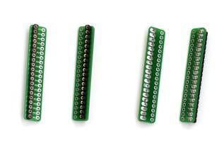
Figure 11. Adapters for the processor board with collet connectors
Thus, the minimum configuration, consisting of a processor board, a budget programmer and a microUSB-USB cable, allows you to master the multicellular processor R1 and to develop and debug various devices.
As well as a complete set of boards, a board with a minimum configuration can be “pumped” to fit your needs by attaching a board with navigation equipment, power switches, and a stepper motor control module as the next floor. The developer of additional modules, which are positioned as Slave-modules is certainly not Xzibit, but it is considering proposals from users for the manufacture of additional modules. Figure 12 shows the navigation module, the module with the power keys and the module for connecting the screen system.
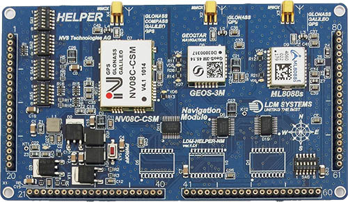
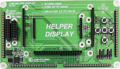
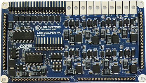
Figure 12. Slave modules
It should be noted that all the circuit diagrams of the boards with the indication of the elements are open, and we recommend using our best practices when creating your own devices. It is possible to work with debugging boards on a PC running Windows, Linux, debug the program in the model and in hardware and develop your own software in C or assembler.
4. Conclusion
And finally, I would like to say that now the development of all the necessary software (including the llvm compiler) is in full swing, the laboratory in the UrFU at the radio engineering institute (IRIT-RTF) has started its work. In the laboratory, sets of the maximum configuration are installed, for the convenience of organizing the educational process. Robotology kits "Robotology" go into mass production, but their specifics are more focused on the development of "Robotics" by schoolchildren, as well as on a quick acquaintance with the domestic processor, although some elements can find their application in industry.
In the near future, we plan to organize free remote access to the debugging board, so that a greater number of those who wish can try working with the board in our environment. We will have a debug board broadcast on youtube so that users can see what is happening. Fedora will be the OS. Connect remotely as users of Linux, Mac and Windows, just enough to request a time interval.
Thanks to everyone who shows interest in our development, and look forward to a new wave of suggestions, criticism and suggestions. It is you who makes us better!
Two years have passed and a replenishment occurred in a multicellular family, and the world saw R1 Multiklet. In this article, we will take a detailed look at the debug kit for the first processor with cell reconfiguration, and also demonstrate the most budgetary version of the debug board.
Figure 1. Sketch processor board
')
1. Expectations and results
Since this article is intended to review the debugging complex, but there may be questions about the processor, so I prepared a list of my publications on processors.
Table of contents
Before developing a new debugging board, competitors were analyzed, and a discussion was held in various forums on what the debugging board should be. As a result, in connection with the expansion of the processor line, so that everyone had enough space in the house and in order to reduce the cost of manufacturing the processor board, it was decided to have a modular structure of the debugging system.
Figures 1 and 2 show thumbnails of the debug board, i.e. what we wanted to get 2 years ago and what we came up with in our community. We express our gratitude to all who shared their advice and participated in the creation of the concept of a new board.
Figure 2. Sketch baseboard
Development of the debug board was entrusted to professionals from LDM-Systems. Of course, we assumed that it would end up because This company has already made a debug board for us for the P1 Multiclet processor. But the result exceeded all our expectations.
A debugging kit was developed, consisting of a base universal board and a processor board connected to it, see Fig.3.
Figure 3. Full debug kit
The R1 processor started up the first time and blinked with LEDs. Of course, to make such a fairly voluminous thing was ideally difficult. But it was from what to make a start and without any problems we came to the debugging version, which I like, and I hope, will satisfy the needs of most of our users. It is worth noting that at some point it was necessary to re-dissolve a lot of lines on the board (once again, I insisted on this, so it was partly my fault that the first users had a slightly delayed delivery date) so that everything would be aesthetic and convenient for users with all the peripheral blocks, as they say "meet on clothes." For which we are very grateful to our masters from LDM-Systems, who built a cozy control point for the Multiklet R1.
2. Overview of the debugging kit
Today, we continue to develop to the best of our abilities, and if we abstract to automotive topics, our model range has replenished and currently includes three types of cars.
The first type is a debugging set consisting of the MB501 baseboard, containing the full set of necessary interfaces, a processor board and the necessary connectors and wires, see Figure 4.
Figure 4. Maximum grade baseboard
The second type is distinguished by a baseboard, called pMB101, which has a somewhat trimmed set of connectors on board, but allows you to use all the necessary interfaces and assemble your device as a compact, ready-made module, see Figure 5.
Figure 5. Compact Baseboard Version
The third type also has a difference in the baseboard version, which is called the uMB301 and allows you to join the processor board in the most compact form, see Figure 6.
Figure 6. Micro Baseboard Version
Thus, we got a complete set of sedan, hatchback and coupe. Figure 7 shows with which main interfaces it is possible to work on the baseboard, although there are also SPI, I2C, I2S and other interfaces that can be used through the pins on the processor or baseplate.
Figure 7. Basic Baseboard Interfaces
We also prepared a video demonstration of the debugging board:
But alternatives are possible to control the multicellular processor, more on this later.
3. Minimum grade
As in the automotive industry, according to numerous requests was issued a minimum set of debug kit. But almost every car bought in the minimum configuration, you can then bring to the configuration "Suite" and buy winter tires. We decided not to depart from this concept and as a result we removed some of the elements of the processor board, as well as the protective housing of the programmer. We did not act as radically as in the Martian film and with our module we dropped only some peripheral components, which allowed us to reduce the cost of producing a processor board from Multiclet R1, taking into account the programmer in the set, to the level of the previous generation debugging board from Multiclet P1.
It turned out the minimum configuration of the processor board, see figure 8.
Figure 8. Processor board with a reduced number of elements
Some components for the operation of the periphery and their binding were not installed on the processor board, in fig. 9 demonstrated these elements.
Figure 9. Basic elements that were not installed on the board.
Thus, the main non-installed components were 2 SRAM memory, 2 SDRAM memory, physical layer chips for USB, ETHERNET. You can bring the processor board to the maximum configuration. To do this, simply contact your authorized dealer or any soldering services salon. For components, you also have the right to decide which ones to install, original or not.
The minimum configuration also includes a programmer without a case (see Fig. 10) and a microUSB USB cable for power supply from the USB port.
Figure 10. Budget version of the programmer
The budget version of the debugging kit is a kind of designer, and in principle, depending on the needs, you can immediately select the elements to be installed. In the absence of a baseboard, and even if it is available, it may be necessary to dock the debugging board with other external user devices. For this purpose, special adapters have been developed from the collet pins of the board, see figure 11.
Figure 11. Adapters for the processor board with collet connectors
Thus, the minimum configuration, consisting of a processor board, a budget programmer and a microUSB-USB cable, allows you to master the multicellular processor R1 and to develop and debug various devices.
As well as a complete set of boards, a board with a minimum configuration can be “pumped” to fit your needs by attaching a board with navigation equipment, power switches, and a stepper motor control module as the next floor. The developer of additional modules, which are positioned as Slave-modules is certainly not Xzibit, but it is considering proposals from users for the manufacture of additional modules. Figure 12 shows the navigation module, the module with the power keys and the module for connecting the screen system.
Figure 12. Slave modules
It should be noted that all the circuit diagrams of the boards with the indication of the elements are open, and we recommend using our best practices when creating your own devices. It is possible to work with debugging boards on a PC running Windows, Linux, debug the program in the model and in hardware and develop your own software in C or assembler.
4. Conclusion
And finally, I would like to say that now the development of all the necessary software (including the llvm compiler) is in full swing, the laboratory in the UrFU at the radio engineering institute (IRIT-RTF) has started its work. In the laboratory, sets of the maximum configuration are installed, for the convenience of organizing the educational process. Robotology kits "Robotology" go into mass production, but their specifics are more focused on the development of "Robotics" by schoolchildren, as well as on a quick acquaintance with the domestic processor, although some elements can find their application in industry.
In the near future, we plan to organize free remote access to the debugging board, so that a greater number of those who wish can try working with the board in our environment. We will have a debug board broadcast on youtube so that users can see what is happening. Fedora will be the OS. Connect remotely as users of Linux, Mac and Windows, just enough to request a time interval.
Thanks to everyone who shows interest in our development, and look forward to a new wave of suggestions, criticism and suggestions. It is you who makes us better!
Source: https://habr.com/ru/post/269287/
All Articles