FlexPod DataCenter: Direct-Attached Storage
In a previous article, I talked about a “non-FlexPod DC” architecture that can be supported from a single source by using the Cisco Solution Support for Critical Infrastructure (SSCI) program. Its main feature is that it does not have Nexus series switches, and if you add them there, such an architecture can become a full-fledged FlexPod DataCenter.
Here we will talk about the new network design for FlexPod DataCenter, with the direct inclusion of NetApp storage systems in the UCS domain. The difference from the standard FlexPod DataCenter architecture is that the Nexus switches are not located between UCS and NetApp, but “on top of” UCS.
Despite the fact that before NetApp FAS series storage systems could be connected directly to Fabric Interconnect (FI), the FlexPod DataCenter architecture did not officially presuppose such a design. Now the direct-on design is supported and sorted, like the FlexPod DataCenter architecture.
')

The overall design of the network FC and FCoE with direct inclusion.
For Ethernet traffic in conjunction with both direct inclusion and iSCSI protocol, as well as direct inclusion and FCP protocol - with the help of multipassing built into these protocols, there is no problem in configuring fault tolerance and link balancing.
But for NAS with direct-on protocols ( NFS v2 / NFS v3 and CIFS v1 / CIFS v2), due to the lack of load balancing and multi-paging within these protocols, some other underlying protocols such as LACP and vPC ( FI does not support vPC ), so the fault tolerance for an Ethernet network will have to be built somehow differently. For example, fault tolerance for Ethernet can be done at the level of a virtual switch (which may have performance problems with such a switch) or by using active-passive switching of an aggregated network link, without LACP (which will not allow balancing traffic across all available links), for this purpose an aggregated link ifgrp , from the storage side, must be configured in single-mode .
The issue of direct-on for NAS protocols is not so hot for NFS v4 and CIFS v3.0, but requires support for these protocols on the client side and storage (all FAS systems with cDOT support NFS v4 and CIFS v3.0), since both protocols Finally, some kind of multipassing has been achieved.
The fact is that NetApp in its new solutions often adheres to the ideology “it is better to outbid than undercook”. So, when I went to the world of Clustered ONTAP for FAS storage systems , it was imperative for the cluster interconnect to have dedicated Nexus 5k switches (for $ 1) exclusively for this task. Over time, this configuration was revised, tested and added the ability to switch-less configurations. Likewise, it took time to test and debug direct storage, first added new Cisco UCS Manager based FC zoning topologies with direct connect (direct connect topologies) storage in the UCS domain, it became available with firmware version Release 2.1 (1a), and then This appeared in the FlexPod architecture.
The configuration with the direct inclusion of storage in FI , in terms of architectural differences, in the case of using block protocols for FC / FCoE / iSCSI access, is the least different from the original design of the FlexPod, where Nexus switches played the role of a link between the storage and the UCS domain. However, in the new design, the Nexus series switches are still a mandatory component of the architecture:
The difference between SAN and NAS designs is that in the case of block protocols, the mechanisms of multipassing and balancing are performed at the FC / FCoE / iSCSI protocol level, and in the case of using NFS / CIFS ( SMB ) protocols, these mechanisms are absent. Multipassing and balancing functions must be performed at the Ethernet level using vPC and LACP , i.e. by means of the switch, which I determine as the determining factor of its presence in such designs.
Despite the fact that Nexus switches are an essential component of the FlexPod DataCenter architecture, a direct connection reduces the cost of such a solution at the first stage of commissioning the complex, i.e. will not buy Nexus switches at the beginning. In other words, you can first assemble non-FlexPod DC . And then buy the switches after a while, spreading budget expenses into a thinner layer and getting a more scalable FlexPod DataCenter architecture, when this is necessary.
Subsequently, the network design can be transformed into a more scalable one, and due to the duplication of components this can be done without stopping the complex.
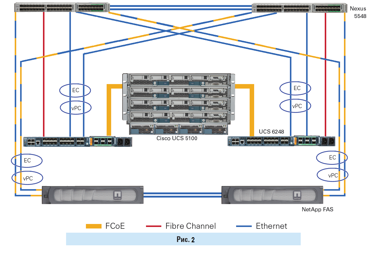
The limitation of the network design presented in Fig.2 is 2 links from one storage controller to the switches, when FCoE and Ethernet traffic go through them simultaneously . If you need to increase the number of links from the storage system, you will have to separate the FCP and Ethernet traffic by separate, dedicated ports and links.
Benefits of FlexPod configurations.
New documents on the implementation of the data center architecture were released: FlexPod Express, Select and DataCenter with Clustered Data ONTAP (cDOT):
I ask to send messages on errors in the text to the LAN .
Notes and additions on the contrary I ask in the comments.
Here we will talk about the new network design for FlexPod DataCenter, with the direct inclusion of NetApp storage systems in the UCS domain. The difference from the standard FlexPod DataCenter architecture is that the Nexus switches are not located between UCS and NetApp, but “on top of” UCS.
Despite the fact that before NetApp FAS series storage systems could be connected directly to Fabric Interconnect (FI), the FlexPod DataCenter architecture did not officially presuppose such a design. Now the direct-on design is supported and sorted, like the FlexPod DataCenter architecture.
')
The overall design of the network FC and FCoE with direct inclusion.
Description of the switching circuit in the image above
Simultaneous connection via FC and FCoE is depicted for two reasons:
The Ethernet connection between two NetApp FAS controllers is depicted for two reasons:
FC link from FI to Nexus switch is depicted for two reasons:
- So really you can do it and it will work.
- To show that you can FC and / or FCoE .
The Ethernet connection between two NetApp FAS controllers is depicted for two reasons:
- To show that these are two nodes of the same ON system (if the node is larger, the picture would necessarily have cluster switches).
- External cluster link is a required accessory of the Clustered DataONTAP operating system.
FC link from FI to Nexus switch is depicted for two reasons:
- For the future. When we need to switch NetApp to Nexus switches and FI get access to their LUNs. After that, the scheme will become more scalable, you can add more UCS domains.
- In order to take resources from storage from other servers that are not included in the UCS domain. For example, UCS Rack servers ( UCS C series) not connected to FI or servers from other manufacturers.
For Ethernet traffic in conjunction with both direct inclusion and iSCSI protocol, as well as direct inclusion and FCP protocol - with the help of multipassing built into these protocols, there is no problem in configuring fault tolerance and link balancing.
But for NAS with direct-on protocols ( NFS v2 / NFS v3 and CIFS v1 / CIFS v2), due to the lack of load balancing and multi-paging within these protocols, some other underlying protocols such as LACP and vPC ( FI does not support vPC ), so the fault tolerance for an Ethernet network will have to be built somehow differently. For example, fault tolerance for Ethernet can be done at the level of a virtual switch (which may have performance problems with such a switch) or by using active-passive switching of an aggregated network link, without LACP (which will not allow balancing traffic across all available links), for this purpose an aggregated link ifgrp , from the storage side, must be configured in single-mode .
The issue of direct-on for NAS protocols is not so hot for NFS v4 and CIFS v3.0, but requires support for these protocols on the client side and storage (all FAS systems with cDOT support NFS v4 and CIFS v3.0), since both protocols Finally, some kind of multipassing has been achieved.
configure FCoE and CIFS / NFS traffic over a single link
Next, go to the settings:
From the NetApp storage side, you need to switch the ports to the CNA state (you need to have CNA ports, regular Ethernet 1 / 10Gbs ports do not support this), using the ucadmin command on the storage system (you will need to restart the storage system ). The system will display independently “virtual” Ethernet ports and “virtual” FC ports, separately (although the physical port will be used for one such “virtual” Ethernet and one “virtual” FC ). These ports are configured separately, like normal physical ports.
On FI, you need to enable the FC mode in the “Switching mode” state, in the Fabric A / B settings on the “Equipment” tab. This setting will require a restart of FI .
If you want to transfer some ports to FC mode, in the Fabric A / B settings on the Equipment tab, select “Configure Unified Ports” and select the required number of FC ports in the wizard (they are selected on the right). FI reboot again.
After rebooting the FI on the “Equipment” tab, convergent or FC ports will need to be transferred to the “Appliance port” mode, after a few seconds the port will go online. Then reconfigure the port in the “FCoE Storage Port” mode or in the “FC Storage Port” mode, in the right pane you will see the port type “ Unified Storage ”. Now it will be possible to choose VSAN and VLAN for such a port. And an important point, created earlier by VSAN , must have included “FC zoning” on FI in order to perform zoning.
Setting zoning for FI:
SAN-> Storage Cloud-> Fabric X-> VSANs-> Create "NetApp-VSAN-600" ->
VSAN ID: 600
FCoE VLAN ID: 3402
FC Zonning Settings: FC Zonning -> Enabled
SAN-> Policies-> vHBA Templates-> Create "vHBA-T1" -> VSAN "NetApp-VSAN-600"
SAN-> Policies-> Storage Connection Policies-> Create “My-NetApp-Conn” -> Zoning Type-> Sist (or Simt if needed) -> Create->
FC Target Endpoint: "NetApp LIF's WWPN" (starts at 20 :)
SAN-> Policies-> SAN Connectivity Policies-> Create "NetApp-Conn-Pol1" -> vHBA Initiator Group->
Create "iGroup1" -> Select vHBA Initiators "vHBA-T1"
Select Storage Connectivity Policy: "My-NetApp-Conn"
When creating a Server Profile, use the created policies and vHBA template.
- First, you need the Cisco UCS firmware version 2.1 or higher.
- Secondly, you need storage with 10GB CNA / UTA ports
Next, go to the settings:
From the NetApp storage side, you need to switch the ports to the CNA state (you need to have CNA ports, regular Ethernet 1 / 10Gbs ports do not support this), using the ucadmin command on the storage system (you will need to restart the storage system ). The system will display independently “virtual” Ethernet ports and “virtual” FC ports, separately (although the physical port will be used for one such “virtual” Ethernet and one “virtual” FC ). These ports are configured separately, like normal physical ports.
On FI, you need to enable the FC mode in the “Switching mode” state, in the Fabric A / B settings on the “Equipment” tab. This setting will require a restart of FI .
If you want to transfer some ports to FC mode, in the Fabric A / B settings on the Equipment tab, select “Configure Unified Ports” and select the required number of FC ports in the wizard (they are selected on the right). FI reboot again.
After rebooting the FI on the “Equipment” tab, convergent or FC ports will need to be transferred to the “Appliance port” mode, after a few seconds the port will go online. Then reconfigure the port in the “FCoE Storage Port” mode or in the “FC Storage Port” mode, in the right pane you will see the port type “ Unified Storage ”. Now it will be possible to choose VSAN and VLAN for such a port. And an important point, created earlier by VSAN , must have included “FC zoning” on FI in order to perform zoning.
Setting zoning for FI:
SAN-> Storage Cloud-> Fabric X-> VSANs-> Create "NetApp-VSAN-600" ->
VSAN ID: 600
FCoE VLAN ID: 3402
FC Zonning Settings: FC Zonning -> Enabled
SAN-> Policies-> vHBA Templates-> Create "vHBA-T1" -> VSAN "NetApp-VSAN-600"
SAN-> Policies-> Storage Connection Policies-> Create “My-NetApp-Conn” -> Zoning Type-> Sist (or Simt if needed) -> Create->
FC Target Endpoint: "NetApp LIF's WWPN" (starts at 20 :)
SAN-> Policies-> SAN Connectivity Policies-> Create "NetApp-Conn-Pol1" -> vHBA Initiator Group->
Create "iGroup1" -> Select vHBA Initiators "vHBA-T1"
Select Storage Connectivity Policy: "My-NetApp-Conn"
When creating a Server Profile, use the created policies and vHBA template.
Why was there no live feed in FlexPod DataCenter before?
The fact is that NetApp in its new solutions often adheres to the ideology “it is better to outbid than undercook”. So, when I went to the world of Clustered ONTAP for FAS storage systems , it was imperative for the cluster interconnect to have dedicated Nexus 5k switches (for $ 1) exclusively for this task. Over time, this configuration was revised, tested and added the ability to switch-less configurations. Likewise, it took time to test and debug direct storage, first added new Cisco UCS Manager based FC zoning topologies with direct connect (direct connect topologies) storage in the UCS domain, it became available with firmware version Release 2.1 (1a), and then This appeared in the FlexPod architecture.
Why do you need Nexus switches?
The configuration with the direct inclusion of storage in FI , in terms of architectural differences, in the case of using block protocols for FC / FCoE / iSCSI access, is the least different from the original design of the FlexPod, where Nexus switches played the role of a link between the storage and the UCS domain. However, in the new design, the Nexus series switches are still a mandatory component of the architecture:
- firstly, because FlexPod must somehow be integrated into the existing infrastructure and provide access to clients
- secondly, live streaming will keep architecture scalability in the future
- thirdly, in contrast to the direct connection with the SAN ( FC / FCoE / iSCSI ), the Ethernet network design for the NAS requires an intermediate link between the storage system and the UCS domain to perform load balancing on the network links, and mainly fault tolerance functions.
- Fourthly, external client access via Ethernet to the FlexPod must be fault tolerant.
Availability of switches for NAS
The difference between SAN and NAS designs is that in the case of block protocols, the mechanisms of multipassing and balancing are performed at the FC / FCoE / iSCSI protocol level, and in the case of using NFS / CIFS ( SMB ) protocols, these mechanisms are absent. Multipassing and balancing functions must be performed at the Ethernet level using vPC and LACP , i.e. by means of the switch, which I determine as the determining factor of its presence in such designs.
How to reduce costs in the first stage
Despite the fact that Nexus switches are an essential component of the FlexPod DataCenter architecture, a direct connection reduces the cost of such a solution at the first stage of commissioning the complex, i.e. will not buy Nexus switches at the beginning. In other words, you can first assemble non-FlexPod DC . And then buy the switches after a while, spreading budget expenses into a thinner layer and getting a more scalable FlexPod DataCenter architecture, when this is necessary.
Subsequently, the network design can be transformed into a more scalable one, and due to the duplication of components this can be done without stopping the complex.
The limitation of the network design presented in Fig.2 is 2 links from one storage controller to the switches, when FCoE and Ethernet traffic go through them simultaneously . If you need to increase the number of links from the storage system, you will have to separate the FCP and Ethernet traffic by separate, dedicated ports and links.
Benefits of FlexPod configurations.
New configurations and designs
New documents on the implementation of the data center architecture were released: FlexPod Express, Select and DataCenter with Clustered Data ONTAP (cDOT):
- Nexus 6000/9000: FlexPod Datacenter with VMware vSphere 5.1U1 and Cisco Nexus 6000 Series Switch Design Guide , FlexPod Datacenter with VMware vSphere 5.5 and Cisco Nexus 9000 Series Switches
- MetroCluster on cDOT (MCC): MetroCluster in Clustered Data ONTAP 8.3 Verification Tests Using Oracle Workloads
- All-Flash FAS (AFF): FlexPod Datacenter with NetApp All-Flash FAS and VMware Horizon (with View) , FlexPod Datacenter with VMware vSphere 5.5 Update and All-Flash FAS .
- FlexPod Express: FlexPod Express with VMware vSphere 5.5: Large Configuration , FlexPod Express with VMware vSphere 5.5 Update 1: Small and Medium configs Implementation Guide .
- Cisco Security: FlexPod Datacenter with Cisco Secure Enclaves
- Cisco ACI : FlexPod Data Center with Microsoft SharePoint 2013 and Cisco Application Centric Infrastructure (ACI) Design Guide , FlexPod Datacenter with VMware vSphere 5.1 U1 and Cisco ACI Design Guide , FlexPod and Cisco ACI - the perfect combination
- FlexPod Select: Oracle RAC NVA Design FlexPod Select for High-Performance
- FlexPod + Veeam Install Guide: How the Veeam Provides for Cisco and NetApp Converged Infrastructures
I ask to send messages on errors in the text to the LAN .
Notes and additions on the contrary I ask in the comments.
Source: https://habr.com/ru/post/268995/
All Articles