DPC without copper
The article was prepared by Vsevolod Vorobiev, head of data center direction of the Center for network solutions of Jet Infosystems
In the spring of this year, we built a large data center for one of the largest domestic banks - VTB24. In one year, we performed a full range of work: from the formation of technical specifications and the development of project documentation to the implementation of commissioning and commissioning of the data center. The data center with an area of 400 m² (excluding hydronic module) is designed for 92 server / network cabinets. Its total power is 1600 kW, the maximum net power is 800 kW.
Figure 1 General data center plan
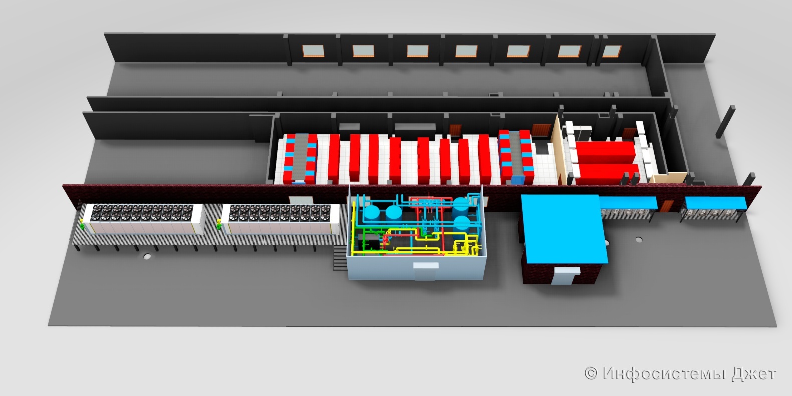
Figure 2 Machine data center
')
After construction, we implemented the following engineering systems:
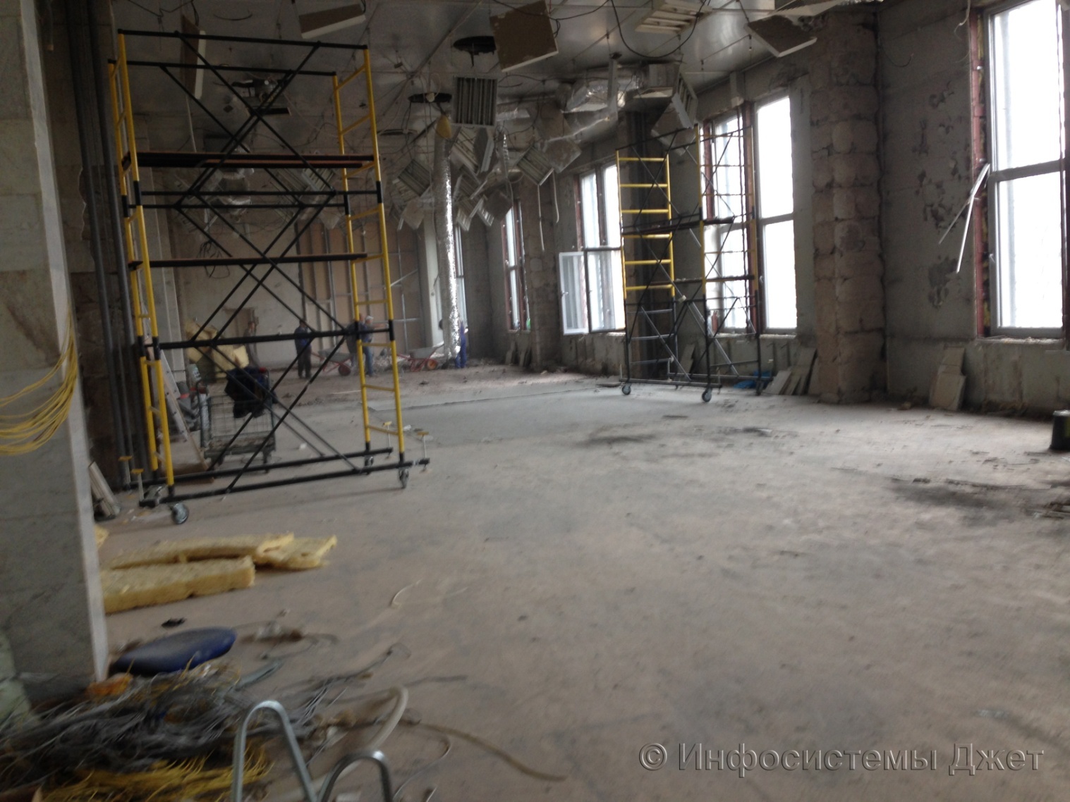
Before the start of work, the allocated areas for the data center were ordinary office space with office furniture. First of all, it was necessary to dismantle all partitions and floor and wall coverings, remove the concrete screed to the concrete slab, level the floor, prime and paint in light-colored paint.
In parallel, there was a dismantling of existing structures in the premises, namely:
Redevelopment of premises implemented in the following volume:
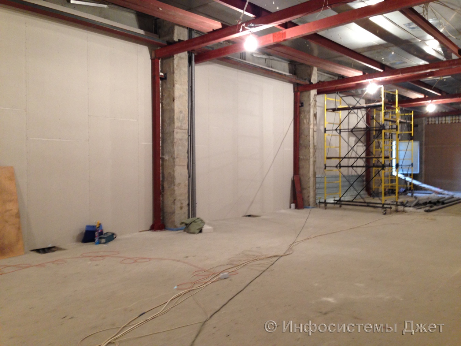
Figure 3: Ceiling frame
The power supply system of the data center is made according to a completely mirror 2N scheme (starting with transformers and ending with PDU in cabinets). Especially for the data center was built a new transformer substation. The UPS complex for IT load consists of two parallel monoblocks of 500 kVA in each arm. For pumps and other air-conditioning consumers, a separate UPS complex is provided. The battery life of the entire UPS system is 20 minutes. A special unloading frame was designed and mounted in the switchboard room for the UPS. All power wiring in the machine room is made in trays in the raised floor space.
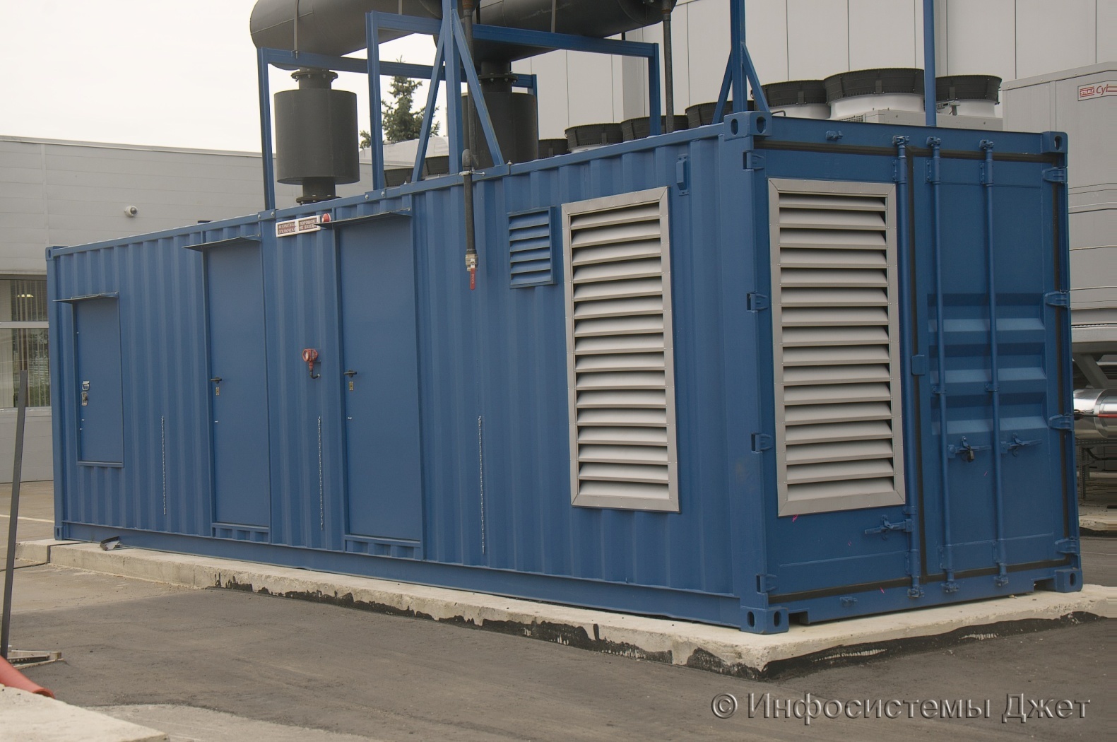
DGUs of street performance in a noise-protected sea container, equipped with a full complex of engineering infrastructure, are installed. To reduce the harmful effects of exhaust on the environment used catalysts with a silver filter.
Figure 4 Container with DGU
The main feature of this project is the characteristics of the air conditioning system. We used powerful energy efficient chillers capable of removing up to 1 MW of heat. In the data center's machine room, both cabinet air conditioners are installed along the perimeter, as well as intra-row air conditioners, which form so-called hermetic zones, in which you can install computing equipment with a capacity of up to 30 kW per rack.
Single-circuit cold supply system. In order to save space in the room itself, an extension to the building was installed for the equipment of the hydronic module. There is a pump group, combs, storage tanks, expansion tanks, etc. in the water module.
All piping is not made in the raised floor space, but in the basement, which potentially reduces the effects of leaks, as well as increases ease of maintenance. The redundancy and maintainability of the system is fully consistent with TIER III from Uptime Instituite.
The coolant in the cold supply circuit is a solution of propylene glycol (42%) with parameters 10/15 ° C. The circulation of the coolant in the main pipelines is provided at the same time along the main and backup pipelines.
The cooling system is equipped with an automatic leak protection system. When the pressure drops in the cooling supply circuit, the automatic shut-off valve closes, dividing it into two independent sections.
The pump group of the external circuit consists of 2 pumps (redundancy scheme "1 + 1").
To maintain system performance in the event of a power failure, 4 battery tanks of 5,000 liters each are provided. The battery life is 20 minutes.
To improve the reliability of the functioning of the system, double input of power supply cables to the installations was used.
Figure 5 Chillers

Figure 6 Cabinet air conditioners
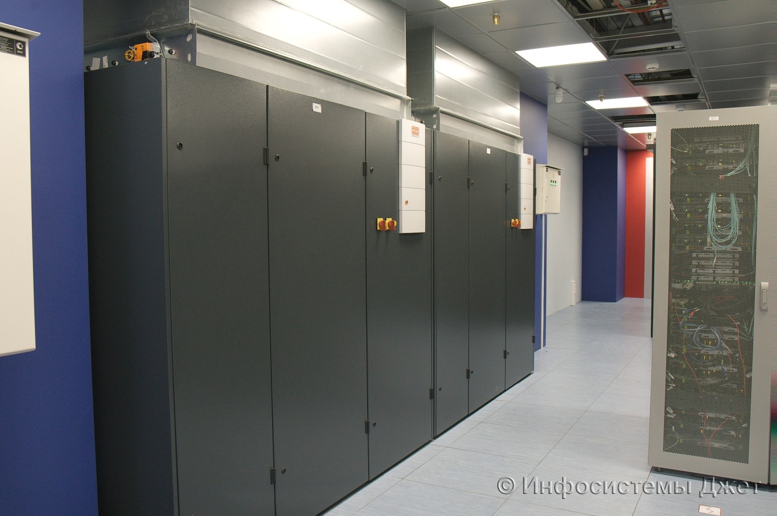
Figure 7 In-row air conditioners

Figure 8 CFD data center model
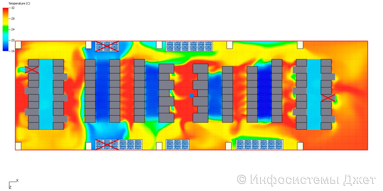
Figure 9 Battery Tanks

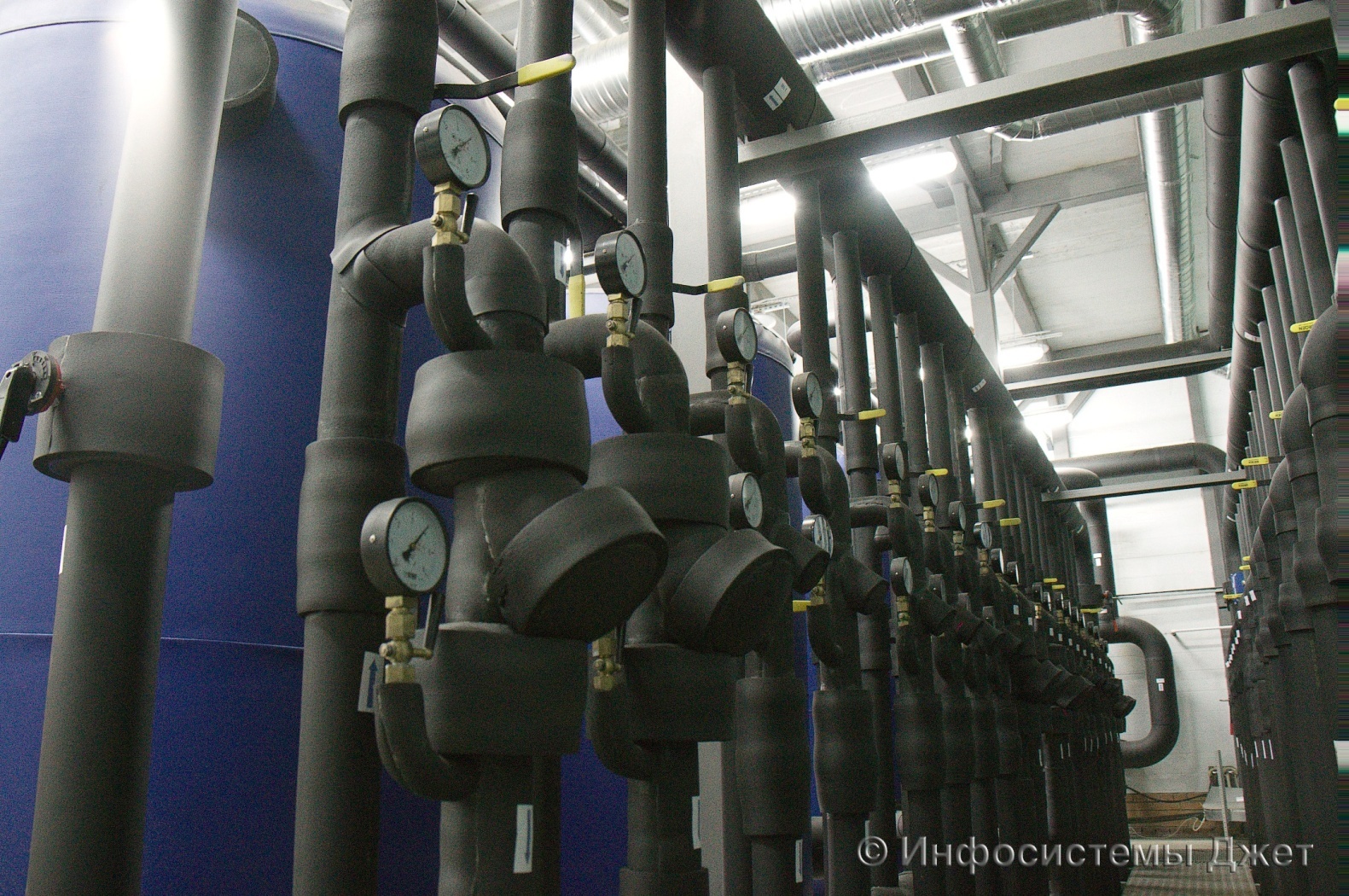
Figure 10 Combs
SCS in this project is not quite normal. The customer decided to organize a topology with a central cross without intermediate nodes. Moreover, the new SCS covers three more existing sites. The scheme of implementation of the central cross - cross-connect. This scheme, although it possesses some redundancy, is completely universal. At the station part of the cross, all ports of the central LAN and SAN switches are cross-linked. Cabinets with switches are locked and only highly qualified personnel has access to them. On the linear side of the cross come links from all server cabinets. The design capacity of the cross is about 18,000 ports! Our engineers were tasked to optimize this solution. An interesting way to organize the cross was the use of MTP-panels (tapes). The cross-over between the fields is also carried out with 12-fiber MTP-cords. Thus, we were able to reduce the number of cabinets under the cross almost 5 times (from 18 to 4 cabinets). This is the first installation of such a solution in the Russian Federation.
Another great advantage of this approach is a painless transition to 40G technology, since the entire line between the switch and the server can be made with 12 fiber MTP cables. In the case of the use of 10 / 16G equipment from the server and the switch, the MTP-LC hydra is used.
The entire SCS of this project is built exclusively on the OM4 / OS2 optics. The wiring is fully implemented in mesh trays in the raised floor space.
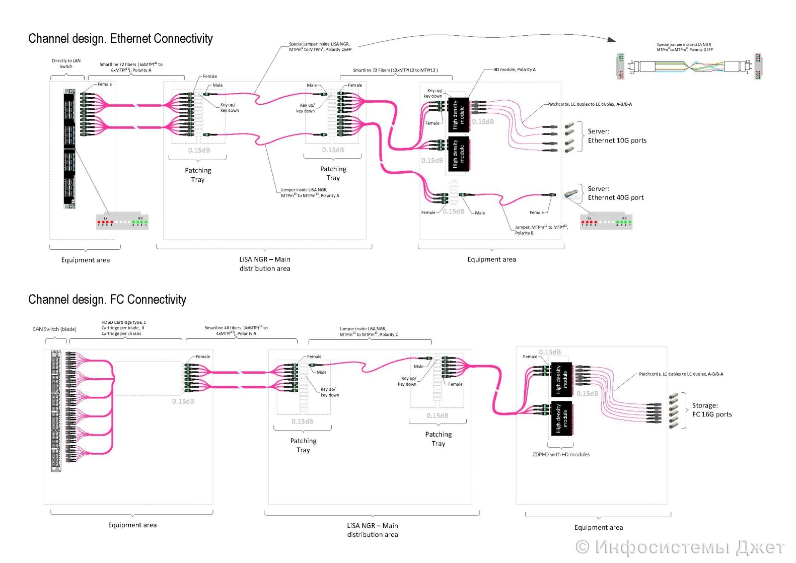
Figure 11 Block diagram of the SCS
Ready to answer additional questions.
In the spring of this year, we built a large data center for one of the largest domestic banks - VTB24. In one year, we performed a full range of work: from the formation of technical specifications and the development of project documentation to the implementation of commissioning and commissioning of the data center. The data center with an area of 400 m² (excluding hydronic module) is designed for 92 server / network cabinets. Its total power is 1600 kW, the maximum net power is 800 kW.
Figure 1 General data center plan
Figure 2 Machine data center
')
After construction, we implemented the following engineering systems:
- raised floor system;
- structured cable system, including cross-connect;
- uninterrupted power supply system;
- power distribution system;
- electric lighting system;
- air conditioning and moisture maintenance;
- ventilation system;
- system of guaranteed power supply (DGU);
- automatic gas fire extinguishing system;
- monitoring system and alarm parameters (power supply, UPS, diesel generator set, air conditioning, room temperature);
- video surveillance system;
- access control system;
- automated dispatch control system.
Construction works
Before the start of work, the allocated areas for the data center were ordinary office space with office furniture. First of all, it was necessary to dismantle all partitions and floor and wall coverings, remove the concrete screed to the concrete slab, level the floor, prime and paint in light-colored paint.
In parallel, there was a dismantling of existing structures in the premises, namely:
- in the premises planned for the placement of the data center and IGU, jammed and dismantled all utilities and other equipment of engineering systems not related to the server room systems, dismantled false ceilings, ducts of the ventilation system;
- dismantled the elements of the existing distribution and low-current power grids;
- removed radiators and risers of the heating system, fan coil units.
Redevelopment of premises implemented in the following volume:
- completed the construction of the ceiling (it protects from flooding from above);
- a false ceiling was mounted in the allocated premises, and its design included metallized plates;
- the existing window openings of the premises were brick-laid;
- in the premises of the data center and I LIE installed a raised floor (its height - 1000 mm). For carrying equipment to the raised floor level provided lifting table.
Figure 3: Ceiling frame
Data Center Power Supply System
The power supply system of the data center is made according to a completely mirror 2N scheme (starting with transformers and ending with PDU in cabinets). Especially for the data center was built a new transformer substation. The UPS complex for IT load consists of two parallel monoblocks of 500 kVA in each arm. For pumps and other air-conditioning consumers, a separate UPS complex is provided. The battery life of the entire UPS system is 20 minutes. A special unloading frame was designed and mounted in the switchboard room for the UPS. All power wiring in the machine room is made in trays in the raised floor space.
DGUs of street performance in a noise-protected sea container, equipped with a full complex of engineering infrastructure, are installed. To reduce the harmful effects of exhaust on the environment used catalysts with a silver filter.
Figure 4 Container with DGU
Air conditioning system
The main feature of this project is the characteristics of the air conditioning system. We used powerful energy efficient chillers capable of removing up to 1 MW of heat. In the data center's machine room, both cabinet air conditioners are installed along the perimeter, as well as intra-row air conditioners, which form so-called hermetic zones, in which you can install computing equipment with a capacity of up to 30 kW per rack.
Single-circuit cold supply system. In order to save space in the room itself, an extension to the building was installed for the equipment of the hydronic module. There is a pump group, combs, storage tanks, expansion tanks, etc. in the water module.
All piping is not made in the raised floor space, but in the basement, which potentially reduces the effects of leaks, as well as increases ease of maintenance. The redundancy and maintainability of the system is fully consistent with TIER III from Uptime Instituite.
The coolant in the cold supply circuit is a solution of propylene glycol (42%) with parameters 10/15 ° C. The circulation of the coolant in the main pipelines is provided at the same time along the main and backup pipelines.
The cooling system is equipped with an automatic leak protection system. When the pressure drops in the cooling supply circuit, the automatic shut-off valve closes, dividing it into two independent sections.
The pump group of the external circuit consists of 2 pumps (redundancy scheme "1 + 1").
To maintain system performance in the event of a power failure, 4 battery tanks of 5,000 liters each are provided. The battery life is 20 minutes.
To improve the reliability of the functioning of the system, double input of power supply cables to the installations was used.
Figure 5 Chillers
Figure 6 Cabinet air conditioners
Figure 7 In-row air conditioners
Figure 8 CFD data center model
Figure 9 Battery Tanks
Figure 10 Combs
Structured Cabling System
SCS in this project is not quite normal. The customer decided to organize a topology with a central cross without intermediate nodes. Moreover, the new SCS covers three more existing sites. The scheme of implementation of the central cross - cross-connect. This scheme, although it possesses some redundancy, is completely universal. At the station part of the cross, all ports of the central LAN and SAN switches are cross-linked. Cabinets with switches are locked and only highly qualified personnel has access to them. On the linear side of the cross come links from all server cabinets. The design capacity of the cross is about 18,000 ports! Our engineers were tasked to optimize this solution. An interesting way to organize the cross was the use of MTP-panels (tapes). The cross-over between the fields is also carried out with 12-fiber MTP-cords. Thus, we were able to reduce the number of cabinets under the cross almost 5 times (from 18 to 4 cabinets). This is the first installation of such a solution in the Russian Federation.
Another great advantage of this approach is a painless transition to 40G technology, since the entire line between the switch and the server can be made with 12 fiber MTP cables. In the case of the use of 10 / 16G equipment from the server and the switch, the MTP-LC hydra is used.
The entire SCS of this project is built exclusively on the OM4 / OS2 optics. The wiring is fully implemented in mesh trays in the raised floor space.
Figure 11 Block diagram of the SCS
Ready to answer additional questions.
Source: https://habr.com/ru/post/268727/
All Articles