DHCP server on multiple VLANs
Formulation of the problem.
The term “client” means the area of responsibility for a set of network devices.
It is required to provide access for several hundred clients to certain shared resources in such a mode so that:
')
As examples of practical application, one can name isolation of local area networks in large organizations, organization of VoIP communications or Internet access for several independent consumers, etc.
Conditions 1 and 2 are achieved by allocating each client its own VLAN. Conditions 3-5 can be accomplished by combining client VLANs with the prohibition of direct traffic between them. In some sources, this technology is called “private VLAN”, in some “port isolation”, and its meaning is this: from each client VLAN you can easily get into some common VLAN (and, accordingly, back), but traffic between the client VLAN is prohibited . Well, to fulfill condition 6, we will allocate for all clients a common address space of the form 10.12.8.0/23, and we will issue specific IP addresses upon request using DHCP.
Thus, when a client gets a new device, the address for it will be issued automatically (and we will have no problems due to the fact that one client can use units of IP addresses for his needs, and another will need tens or hundreds of them), and when adding a new client, we will simply create another VLAN and add it to our common group. Even if, due to the large number of client devices, the address space we initially allocated is exhausted, we can always expand it by changing the settings in just two places (on the DHCP server and on the interface that unites all client VLANs).
Technically, the above solution can be implemented only by hardware on L3 switches or by firmware on L2 switches (as long as they understand 802.1q) and on any computer with a linux-like operating system. Since I already had a server (which, besides, was a target for clients), it would be logical to stop at the hardware-software version.
So, we program the switch so that on each client VLAN there is one physical port of the switch in the “access mode”, and one common port in 802.1q mode (our server will be connected to this port). In detail, the technology settings do not sign, because it is rather trivial and depends on the specific model of switch used.
Next, proceed to creating a configuration for the server. Let the physical interface that connects to the 802.1q port of the switch be named eth0. For my specific task, it took 200 client VLANs with a VLAN ID from 600 to 799, inclusive, so we will create them:
General configuration of types of names of VLAN-interfaces. I want the VLAN interface names to be “vlanXXX”, where XXX is the VLAN ID:
Directly create a VLAN based on the interface eth0:
Create a bridge into which we will merge the created vlans:
We unite the created interfaces in the bridge:
Now we write the address br1 on the interface, which will act as a default gateway for all our clients:
And prohibit traffic between client VLANs using ebtables:
(in this case, the ebtables 'filter' table is used, which prohibits the transfer of traffic between interfaces entering the bridge in the form of logical ports). If it is nevertheless necessary to allow the possibility of transferring traffic between clients under our control (see clause 3 of the technical assignment), then instead of the above rule, we establish the following:
Here we work with the 'broute' table. It does not have standard actions for the purposes of ACCEPT and DROP. The ACCEPT target allows forwarding traffic with specified conditions (ie, traffic is transmitted at the L2 level), and the DROP target denies forwarding traffic and ensures its transmission to the routing (and, accordingly, we will be able to manage it through iptables). However, since all addresses belong to the same IP subnet but can be in different client VLANs, on the br1 interface you will need to enable arp proxy:
I note that I did not have the task of passing traffic between customers, so the extension described above is purely speculative and has not been tested in practice!
It remains only to configure the DHCP server and settle it on the interface br1. This operation is also trivial, therefore it is not described in this article.
Well, does it work? But as if not so:
Everything is fine here: we received one broadcast DHCPDISCOVER request, responded with one broadcast-response DHCPOFFER.
And now let's see what happens on the physical interface:
What happened? Yes, everything as we configured:
Not only did we spotlight the MAC / IP addresses of one of them to all our clients, but we also received an unpretentious broadcast storm on the physical switch. By the way, from such a storm, some switches just have a roof: QTECH, working for us, not only couldn’t miss a broadcast to all the declared 200 client VLANs (i.e., the final client with an arbitrary probability either received its address from a DHCP server, or did not wait for no response at all), but even forgot the table of MAC addresses known to it (at least in the console it showed only one MAC address for all ports). But the ASOTEL switch handled this load and clients could get addresses from our DHCP server.
Well, we will correct the situation. It is necessary to force the server to send a broadcast only to the VLAN from which the initial request came, and not to propagate it to all available places.
Module DHCP tracking broadcast-s I have not found. As it turned out later, he would not have helped in this case anyway, since The broadcast response by the DHCP server is generated using a system call.
socket (PF_PACKET, SOCK_DGRAM, htons (ETH_P_IP))
which does not pass through any of the ebtables or iptables tables. Those. if it is still possible to catch incoming broadcast, then the answers are transmitted to the driver bypassing the protocol stack. And this is logical: if we ourselves form an ethernet header, then what's the point of additionally processing it with the kernel?
Okay, let's try to hang on each client VLAN via DHCP Relay Agent and already send requests from it to the DHCP server for processing. However, it turned out that the Relay Agent does not catch requests from the interfaces entering the bridge (well, this is also probably logical). As soon as the interface was removed from the bridge, the Relay Agent started to retrieve requests, send them to the server and send the answers back to the VLAN to which you need. When you re-add the VLAN to the bridge, the agent’s performance was again broken and DHCP became unavailable to clients.
“Well, okay!” Said the harsh Siberian men. We will do everything in an adult way.
First, remember that modern linux kernels have goodies such as the Virtual Ethernet Device (you can make good pipes to distill ethernet traffic inside our computer) and Network Namespace (a means to isolate the network stack. In hardware routers, this is usually called VRF). In principle, only Virtual Ethernet (veth) can be done for this task, but for the beauty of the solution (and simplification of the DHCP Server bundle - DHCP Relay Agent) we will also use the Network Namespace (netns).
After network initialization in linux, by default there is only one root netns, which contains a single copy of the network stack, routing tables, interfaces, etc. In the following description, for definiteness, we will use the following terminology:
Network Namespace is called a “layer” (layer);
root netns is called the “backplate” layer (although in reality this netns has a name in the form of an empty string);
Our idea is:
We add each client VLAN to a separate bridge, on the interface of which we will hang the DHCP Relay Agent. Through this interface, customers can send broadcast requests to the agent and receive broadcast responses from it.
from each client bridge we make an ethernet pipe to our main br1. Through the link “customer vlan” - “customer vlan bridge” - “virtual ethernet” - ”br1” there will pass the useful traffic between the customer service and the common external resources.
The DHCP Relay Agent itself lives in one instance (it can listen to several client interfaces) on a special ethernet pipe, on the other side of which is our DHCP Server.
the entire application layer (i.e., everything that does not concern DHCP) is located at the backplate level;
everything connected with the DHCP Relay Agent is located at the level called “relay”;
the DHCP server itself must be available both for the DHCP Relay Agent (for processing messages distributed as broadcast and converted by the agent to unicast and back), as well as directly for DHCP clients (for handling special cases: DHCPRELEASE messages sent by unicast client directly to the DHCP volume -server that gave this address).
Taking into account these requirements, the DHCP server itself is located at the backplate level on the br1 interface, but to prevent them from receiving broadcast requests from the end clients, special filters will be applied to the interface.
Well, let's go ... Create a “relay” layer
Create a virtual pipe on the backplate layer, designed for communication between the DHCP Relay Agent and the DHCP Server:
Transfer the dhcpd tail (the interface on which the Relay Agent will work) to the relay layer:
Configure the dhcpd interface in the relay layer:
We create our main bridge br1:
Let this bridge work as a smart switch (i.e., it keeps a table of MAC addresses and performs forwarding to a specific port depending on the presence of a target address on it). To do this, set the learning time to 30 seconds:
Well, clients are peculiar personalities, they can quite create rings. If anyone does this, then let him suffer himself, without affecting others. Those. run on our virtual STP switch:
Since Since this bridge is also the default gateway for clients, then hang up the IP address (along with the grid) and directly raise the interface itself:
Add an interface to the bridge over which the DHCP server will communicate with the agent:
Forbid traffic between client VLANs using ebtables:
We prohibit the DHCP server to process broadcast requests (they must be caught by the agent and sent to the server as unicast):
For security, we allow the use of the address allocated for the DHCP Relay Agent only on the interface named relay:
Okay, last brushstroke. Since I categorically do not trust clients, let the kernel make sure that the IP packets coming from them have the source address of the type 10.12.8.0/23 (and not, for example, 192.168.1.1). For this we enable on the rp filter interface:
We will not transfer the eth0 physical interface from the backplate to the relay layer (well, let's say we will need to hang on it some other application VLANs that are not related to this scheme). Therefore, we will first create VLAN interfaces on the backplate layer, and then transfer them to the relay layer:
General configuration of the types of names of VLAN-interfaces. I want the VLAN interface names to be “vlanXXX”, where XXX is the VLAN ID:
Directly create a VLAN based on the interface eth0:
Transfer the created vlan600 interface from the backplate layer to the relay layer:
We lift the vlan600 interface, but already in the relay layer:
Create a bridge in the relay layer for this client VLAN (to which we will hang the DHCP Relay Agent).
We want this bridge to work as a hub (i.e., perform the broadcast of the packet immediately after receiving it, without using the period for collecting MAC address information). To do this, before adding the first interface to the bridge, set its parameters:
In addition, we clearly do not need STP on this bridge:
Raise the bridge interface:
And add the client VLAN to it:
Create a backplate on the layer (well, it will come there anyway) ethernet pipe for the br600 client bridge and our main bridge br1:
Transfer the second end of the pipe to the relay layer:
And add this end of the pipe to the bridge:
Well, add the end of the pipe remaining in the backplate layer to the bridge br1:
Repeat in the cycle of creating client VLANs in the required quantity.
Now it is enough to start the DHCP server itself in the backplate layer and the DHCP Relay Agent in the relay layer. In my case, I use an assembly from BusyBox, which in this case is not critical. The use of an ISC agent and server should not cause much difficulty.
So, we start the agent. The client interfaces are the br600-br799, the dhcpd interface is used as the interface for communicating with the DHCP server, and the DHCP server itself has the address 10.12.8.1:
And finally, we start the DHCP server:
The file /etc/udhcpd.conf is the only line that relates to this schema:
All, now the broadcast requests in the user VLAN are caught by the DHCP Relay Agent via the corresponding br interface, after which the unicast request is transmitted to the server via the dhcpd interface. The server sends a unicast response via the relay interface, which the agent receives from the dhcpd interface and transmits the broadcast to the source VLAN.
Clients began to receive addresses through DHCP, broadcast-storm disappeared. And the client can send DHCPRELEASE directly to the server to the address 10.12.8.1
© Copiright 2015 by Vedga . Copying text to other resources without the consent of the author is prohibited.
What to look at this article:
The term “client” means the area of responsibility for a set of network devices.
It is required to provide access for several hundred clients to certain shared resources in such a mode so that:
')
- Each client did not see the traffic of other clients.
- Malfunctions of one client (broadcast-storm, IP address conflicts, unauthorized client DHCP servers, etc.) should not affect the operation of other clients as well as the system as a whole.
- Each client should not directly access the resources of other clients (although, as a special case, it is possible to provide for the permission of this traffic, but with its centralized control and / or control).
- Clients should be able to gain access to shared external resources (which can be both individual servers and the Internet as a whole).
- Shared resources should also be able to access client resources (of course, provided that the shared resource knows the IP address of the client resource).
- The address space for clients is allocated centrally and its administration should not be overly complex.
As examples of practical application, one can name isolation of local area networks in large organizations, organization of VoIP communications or Internet access for several independent consumers, etc.
Conditions 1 and 2 are achieved by allocating each client its own VLAN. Conditions 3-5 can be accomplished by combining client VLANs with the prohibition of direct traffic between them. In some sources, this technology is called “private VLAN”, in some “port isolation”, and its meaning is this: from each client VLAN you can easily get into some common VLAN (and, accordingly, back), but traffic between the client VLAN is prohibited . Well, to fulfill condition 6, we will allocate for all clients a common address space of the form 10.12.8.0/23, and we will issue specific IP addresses upon request using DHCP.
Thus, when a client gets a new device, the address for it will be issued automatically (and we will have no problems due to the fact that one client can use units of IP addresses for his needs, and another will need tens or hundreds of them), and when adding a new client, we will simply create another VLAN and add it to our common group. Even if, due to the large number of client devices, the address space we initially allocated is exhausted, we can always expand it by changing the settings in just two places (on the DHCP server and on the interface that unites all client VLANs).
Technically, the above solution can be implemented only by hardware on L3 switches or by firmware on L2 switches (as long as they understand 802.1q) and on any computer with a linux-like operating system. Since I already had a server (which, besides, was a target for clients), it would be logical to stop at the hardware-software version.
So, we program the switch so that on each client VLAN there is one physical port of the switch in the “access mode”, and one common port in 802.1q mode (our server will be connected to this port). In detail, the technology settings do not sign, because it is rather trivial and depends on the specific model of switch used.
Next, proceed to creating a configuration for the server. Let the physical interface that connects to the 802.1q port of the switch be named eth0. For my specific task, it took 200 client VLANs with a VLAN ID from 600 to 799, inclusive, so we will create them:
General configuration of types of names of VLAN-interfaces. I want the VLAN interface names to be “vlanXXX”, where XXX is the VLAN ID:
vconfig set_name_type VLAN_PLUS_VID_NO_PAD
Directly create a VLAN based on the interface eth0:
 vconfig add eth0 600
 ifconfig vlan600 up
 vconfig add eth0 601
 ifconfig vlan601 up
 ...
 vconfig add eth0 799
 ifconfig vlan799 up
Create a bridge into which we will merge the created vlans:
 brctl addbr br1
 ifconfig br1 up
We unite the created interfaces in the bridge:
 brctl addif br1 vlan600
 brctl addif br1 vlan601
 ...
 brctl addif br1 vlan799
Now we write the address br1 on the interface, which will act as a default gateway for all our clients:
ifconfig br1 10.12.8.1/23
And prohibit traffic between client VLANs using ebtables:
ebtables -A FORWARD --logical-in br1 --logical-out br1 -j DROP
(in this case, the ebtables 'filter' table is used, which prohibits the transfer of traffic between interfaces entering the bridge in the form of logical ports). If it is nevertheless necessary to allow the possibility of transferring traffic between clients under our control (see clause 3 of the technical assignment), then instead of the above rule, we establish the following:
 ebtables -t broute -A BROUTING -p ipv4 --logical-in -j DROP
 ebtables -t broute -A BROUTING -p arp --logical-in -j DROP
Here we work with the 'broute' table. It does not have standard actions for the purposes of ACCEPT and DROP. The ACCEPT target allows forwarding traffic with specified conditions (ie, traffic is transmitted at the L2 level), and the DROP target denies forwarding traffic and ensures its transmission to the routing (and, accordingly, we will be able to manage it through iptables). However, since all addresses belong to the same IP subnet but can be in different client VLANs, on the br1 interface you will need to enable arp proxy:
sysctl -w net.ipv4.conf.br1.proxy_arp = 1
I note that I did not have the task of passing traffic between customers, so the extension described above is purely speculative and has not been tested in practice!
It remains only to configure the DHCP server and settle it on the interface br1. This operation is also trivial, therefore it is not described in this article.
Well, does it work? But as if not so:
 # tcpdump -e -v -n -i br1 udp port 67 or port 68
 tcpdump: listening on br1, link-type EN10MB (Ethernet), capture size 65535 bytes
 14: 26: 38.164169 00: 0b: 82: 3b: 9c: 96> ff: ff: ff: ff: ff: ff, ethertype IPv4 (0x0800), length 590: (tos 0x0, ttl 64, id 0, offset 0 , flags [none], proto UDP (17), length 576)
     0.0.0.0.68> 255.255.255.255.67: BOOTP / DHCP, Request from 00: 0b: 82: 3b: 9c: 96, length 548, xid 0x3c12d61a, Flags [none]
           Client-Ethernet-Address 00: 0b: 82: 3b: 9c: 96
           Vendor-rfc1048 Extensions
             Magic Cookie 0x63825363
             DHCP-Message Option 53, length 1: Discover
             Client-ID Option 61, length 7: ether 00: 0b: 82: 3b: 9c: 96
             Vendor-Class Option 60, length 16: "GXV dslforum.org"
             T125 Option 125, length 36: 3561,520160816,808469048,838994992,808469048,842220089,11272851,122116182.858862640
             Parameter-Request Option 55, length 11:
               Subnet-Mask, Time-Zone, Default-Gateway, Domain-Name-Server
               Hostname, Domain Name, BR, NTP
               Vendor-Option, TFTP, Option 125
 14: 26: 38.171041 00: 25: 90: d3: 5e: fa> ff: ff: ff: ff: ff: ff, ethertype IPv4 (0x0800), length 336: (tos 0x0, ttl 64, id 0, offset 0 , flags [none], proto UDP (17), length 322)
     12/10/8.1.67> 255.255.255.255.68: BOOTP / DHCP, Reply, length 294, xid 0x3c12d61a, Flags [none]
           Your-IP 10.12.8.200
           Client-Ethernet-Address 00: 0b: 82: 3b: 9c: 96
           Vendor-rfc1048 Extensions
             Magic Cookie 0x63825363
             DHCP-Message Option 53, length 1: Offer
             Server-ID Option 54, length 4: 10.12.8.1
             Lease-Time Option 51, length 4: 7200
             Subnet-Mask Option 1, length 4: 255.255.254.0
             Default-Gateway Option 3, length 4: 10.12.8.1
Everything is fine here: we received one broadcast DHCPDISCOVER request, responded with one broadcast-response DHCPOFFER.
And now let's see what happens on the physical interface:
 # tcpdump -e -n -i eth0 udp port 67 or port 68
 tcpdump: WARNING: eth0: no IPv4 address assigned
 tcpdump: verbose output suppressed, use -v or -vv for full protocol decode
 listening on eth0, link-type EN10MB (Ethernet), capture size 65535 bytes
 14: 31: 07.829289 00: 0b: 82: 3b: 9c: 96> ff: ff: ff: ff: ff: ff, ethertype 802.1Q (0x8100), length 594: vlan 603, p 0, ethertype IPv4, 0.0. 0.0.68> 255.255.255.255.67: BOOTP / DHCP, Request from 00: 0b: 82: 3b: 9c: 96, length 548
 14: 31: 07.834962 00: 25: 90: d3: 5e: fa> ff: ff: ff: ff: ff: ff, ethertype 802.1Q (0x8100), length 340: vlan 799, p 0, ethertype IPv4, 10.12. 8.1.67> 255.255.255.255.68: BOOTP / DHCP, Reply, length 294
 14: 31: 07.834966 00: 25: 90: d3: 5e: fa> ff: ff: ff: ff: ff: ff, ethertype 802.1Q (0x8100), length 340: vlan 798, p 0, ethertype IPv4, 10.12. 8.1.67> 255.255.255.255.68: BOOTP / DHCP, Reply, length 294
 14: 31: 07.834968 00: 25: 90: d3: 5e: fa> ff: ff: ff: ff: ff: ff, ethertype 802.1Q (0x8100), length 340: vlan 797, p 0, ethertype IPv4, 10.12. 8.1.67> 255.255.255.255.68: BOOTP / DHCP, Reply, length 294
 14: 31: 07.834970 00: 25: 90: d3: 5e: fa> ff: ff: ff: ff: ff: ff, ethertype 802.1Q (0x8100), length 340: vlan 796, p 0, ethertype IPv4, 10.12. 8.1.67> 255.255.255.255.68: BOOTP / DHCP, Reply, length 294
 14: 31: 07.834972 00: 25: 90: d3: 5e: fa> ff: ff: ff: ff: ff: ff, ethertype 802.1Q (0x8100), length 340: vlan 795, p 0, ethertype IPv4, 10.12. 8.1.67> 255.255.255.255.68: BOOTP / DHCP, Reply, length 294
 14: 31: 07.834974 00: 25: 90: d3: 5e: fa> ff: ff: ff: ff: ff: ff, ethertype 802.1Q (0x8100), length 340: vlan 794, p 0, ethertype IPv4, 10.12. 8.1.67> 255.255.255.255.68: BOOTP / DHCP, Reply, length 294
 14: 31: 07.834976 00: 25: 90: d3: 5e: fa> ff: ff: ff: ff: ff: ff, ethertype 802.1Q (0x8100), length 340: vlan 793, p 0, ethertype IPv4, 10.12. 8.1.67> 255.255.255.255.68: BOOTP / DHCP, Reply, length 294
 14: 31: 07.834978 00: 25: 90: d3: 5e: fa> ff: ff: ff: ff: ff: ff, ethertype 802.1Q (0x8100), length 340: vlan 792, p 0, ethertype IPv4, 10.12. 8.1.67> 255.255.255.255.68: BOOTP / DHCP, Reply, length 294
 ...
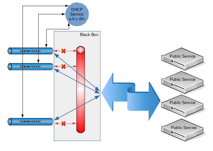
What happened? Yes, everything as we configured:
- DHCPDISCOVER was received from VLAN 603;
- the request was transmitted via the br1 interface to our DHCP server;
- the server responded to it by sending a DHCPOFFER response to the br1 interface;
- The br1 interface propagated this response (since it, according to the DHCP standard, is broadcast in both L3 and L2 levels) across all client VLANs.
Not only did we spotlight the MAC / IP addresses of one of them to all our clients, but we also received an unpretentious broadcast storm on the physical switch. By the way, from such a storm, some switches just have a roof: QTECH, working for us, not only couldn’t miss a broadcast to all the declared 200 client VLANs (i.e., the final client with an arbitrary probability either received its address from a DHCP server, or did not wait for no response at all), but even forgot the table of MAC addresses known to it (at least in the console it showed only one MAC address for all ports). But the ASOTEL switch handled this load and clients could get addresses from our DHCP server.
Well, we will correct the situation. It is necessary to force the server to send a broadcast only to the VLAN from which the initial request came, and not to propagate it to all available places.
Module DHCP tracking broadcast-s I have not found. As it turned out later, he would not have helped in this case anyway, since The broadcast response by the DHCP server is generated using a system call.
socket (PF_PACKET, SOCK_DGRAM, htons (ETH_P_IP))
which does not pass through any of the ebtables or iptables tables. Those. if it is still possible to catch incoming broadcast, then the answers are transmitted to the driver bypassing the protocol stack. And this is logical: if we ourselves form an ethernet header, then what's the point of additionally processing it with the kernel?
Okay, let's try to hang on each client VLAN via DHCP Relay Agent and already send requests from it to the DHCP server for processing. However, it turned out that the Relay Agent does not catch requests from the interfaces entering the bridge (well, this is also probably logical). As soon as the interface was removed from the bridge, the Relay Agent started to retrieve requests, send them to the server and send the answers back to the VLAN to which you need. When you re-add the VLAN to the bridge, the agent’s performance was again broken and DHCP became unavailable to clients.
“Well, okay!” Said the harsh Siberian men. We will do everything in an adult way.
First, remember that modern linux kernels have goodies such as the Virtual Ethernet Device (you can make good pipes to distill ethernet traffic inside our computer) and Network Namespace (a means to isolate the network stack. In hardware routers, this is usually called VRF). In principle, only Virtual Ethernet (veth) can be done for this task, but for the beauty of the solution (and simplification of the DHCP Server bundle - DHCP Relay Agent) we will also use the Network Namespace (netns).
After network initialization in linux, by default there is only one root netns, which contains a single copy of the network stack, routing tables, interfaces, etc. In the following description, for definiteness, we will use the following terminology:
Network Namespace is called a “layer” (layer);
root netns is called the “backplate” layer (although in reality this netns has a name in the form of an empty string);
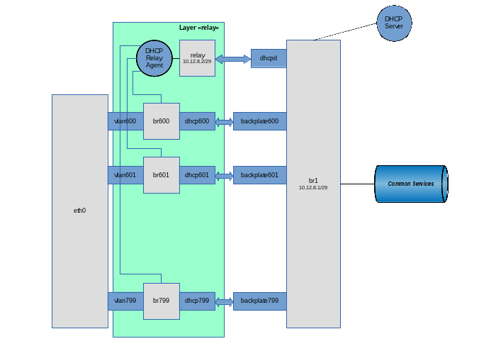
Our idea is:
We add each client VLAN to a separate bridge, on the interface of which we will hang the DHCP Relay Agent. Through this interface, customers can send broadcast requests to the agent and receive broadcast responses from it.
from each client bridge we make an ethernet pipe to our main br1. Through the link “customer vlan” - “customer vlan bridge” - “virtual ethernet” - ”br1” there will pass the useful traffic between the customer service and the common external resources.
The DHCP Relay Agent itself lives in one instance (it can listen to several client interfaces) on a special ethernet pipe, on the other side of which is our DHCP Server.
the entire application layer (i.e., everything that does not concern DHCP) is located at the backplate level;
everything connected with the DHCP Relay Agent is located at the level called “relay”;
the DHCP server itself must be available both for the DHCP Relay Agent (for processing messages distributed as broadcast and converted by the agent to unicast and back), as well as directly for DHCP clients (for handling special cases: DHCPRELEASE messages sent by unicast client directly to the DHCP volume -server that gave this address).
Taking into account these requirements, the DHCP server itself is located at the backplate level on the br1 interface, but to prevent them from receiving broadcast requests from the end clients, special filters will be applied to the interface.
Well, let's go ... Create a “relay” layer
ip netns add relay
Create a virtual pipe on the backplate layer, designed for communication between the DHCP Relay Agent and the DHCP Server:
ip link add relay type veth peer name dhcpd
Transfer the dhcpd tail (the interface on which the Relay Agent will work) to the relay layer:
ip link set dhcpd netns relay
Configure the dhcpd interface in the relay layer:
 ip netns exec relay ifconfig dhcpd 10.12.8.2/23
 ip netns exec relay ifconfig dhcpd up
We create our main bridge br1:
brctl addbr br1
Let this bridge work as a smart switch (i.e., it keeps a table of MAC addresses and performs forwarding to a specific port depending on the presence of a target address on it). To do this, set the learning time to 30 seconds:
brctl setfd br1 30
Well, clients are peculiar personalities, they can quite create rings. If anyone does this, then let him suffer himself, without affecting others. Those. run on our virtual STP switch:
brctl stp br1 on
Since Since this bridge is also the default gateway for clients, then hang up the IP address (along with the grid) and directly raise the interface itself:
 ifconfig br1 10.12.8.1/23
 ifconfig br1 up
Add an interface to the bridge over which the DHCP server will communicate with the agent:
brctl addif br1 relay
Forbid traffic between client VLANs using ebtables:
ebtables -A FORWARD --logical-in br1 --logical-out br1 -j DROP
We prohibit the DHCP server to process broadcast requests (they must be caught by the agent and sent to the server as unicast):
ebtables -A INPUT --log-in br1 --pkttype-type broadcast --protocol IPv4 --ip-protocol udp --ip-destination-port 67 -j DROP
For security, we allow the use of the address allocated for the DHCP Relay Agent only on the interface named relay:
ebtables -A INPUT --in-interface! relay --protocol IPv4 --ip-source 10.12.8.2/32 -j DROP
Okay, last brushstroke. Since I categorically do not trust clients, let the kernel make sure that the IP packets coming from them have the source address of the type 10.12.8.0/23 (and not, for example, 192.168.1.1). For this we enable on the rp filter interface:
sysctl -w net.ipv4.conf.br1.rp_filter = 1
We will not transfer the eth0 physical interface from the backplate to the relay layer (well, let's say we will need to hang on it some other application VLANs that are not related to this scheme). Therefore, we will first create VLAN interfaces on the backplate layer, and then transfer them to the relay layer:
General configuration of the types of names of VLAN-interfaces. I want the VLAN interface names to be “vlanXXX”, where XXX is the VLAN ID:
vconfig set_name_type VLAN_PLUS_VID_NO_PAD
Directly create a VLAN based on the interface eth0:
vconfig add eth0 600
Transfer the created vlan600 interface from the backplate layer to the relay layer:
ip link set vlan600 netns relay
We lift the vlan600 interface, but already in the relay layer:
ip netns exec relay ifconfig vlan600 up
Create a bridge in the relay layer for this client VLAN (to which we will hang the DHCP Relay Agent).
ip netns exec relay brctl addbr br600
We want this bridge to work as a hub (i.e., perform the broadcast of the packet immediately after receiving it, without using the period for collecting MAC address information). To do this, before adding the first interface to the bridge, set its parameters:
ip netns exec relay brctl setfd br600 0
In addition, we clearly do not need STP on this bridge:
ip netns exec relay brctl stp br600 off
Raise the bridge interface:
ip netns exec relay ifconfig br600 up
And add the client VLAN to it:
ip netns exec relay brctl addif br600 vlan600
Create a backplate on the layer (well, it will come there anyway) ethernet pipe for the br600 client bridge and our main bridge br1:
ip link add dhcp600 type veth peer name backplate600
Transfer the second end of the pipe to the relay layer:
ip link set backplate600 netns relay
And add this end of the pipe to the bridge:
ip netns exec relay brctl addif br600 backplate600
Well, add the end of the pipe remaining in the backplate layer to the bridge br1:
brctl addif br1 dhcp600
Repeat in the cycle of creating client VLANs in the required quantity.
Now it is enough to start the DHCP server itself in the backplate layer and the DHCP Relay Agent in the relay layer. In my case, I use an assembly from BusyBox, which in this case is not critical. The use of an ISC agent and server should not cause much difficulty.
So, we start the agent. The client interfaces are the br600-br799, the dhcpd interface is used as the interface for communicating with the DHCP server, and the DHCP server itself has the address 10.12.8.1:
ip netns exec relay / usr / sbin / dhcprelay br600, br601, ..., br799 dhcpd 10.12.8.1
And finally, we start the DHCP server:
/ usr / sbin / udhcpd /etc/udhcpd.conf
The file /etc/udhcpd.conf is the only line that relates to this schema:
 # The name of the interface on which we have a DHCP server
 interface br1
All, now the broadcast requests in the user VLAN are caught by the DHCP Relay Agent via the corresponding br interface, after which the unicast request is transmitted to the server via the dhcpd interface. The server sends a unicast response via the relay interface, which the agent receives from the dhcpd interface and transmits the broadcast to the source VLAN.
Clients began to receive addresses through DHCP, broadcast-storm disappeared. And the client can send DHCPRELEASE directly to the server to the address 10.12.8.1
© Copiright 2015 by Vedga . Copying text to other resources without the consent of the author is prohibited.
What to look at this article:
Source: https://habr.com/ru/post/268331/
All Articles