We are switching from STM32 to the Russian K1986BE92QI microcontroller. Practical application: We interrogate keys, we generate PWM. Comparison of CMSIS and SPL code (PWM + TIM + PORT). Part one
Introduction
Retreat
A lot of time has passed from the last article I wrote, for which I apologize: the Unified State Exam, admission, the beginning of studies. Now, when the session is still far away, and the learning process does not take much time, I can continue to write articles about mastering our K1986BE92QI.
Work plan
In the comments to the previous articles I was asked to highlight not only the work with the microcontroller through the setting of registers, but also using SPL (Universal Library for auto-configuration of peripherals.). When we first started, I wouldn’t do that, because the temptation to use SPL instead of manual tuning using CMSIS would be great, and you would very likely, contrary to common sense, start using SPL everywhere you could. Now, having learned to work with some blocks of the periphery manually, we can touch the SPL and compare the efficiency of both approaches in a real task.
purpose
As a learning goal, let's blink the LED by means of PWM (Pulse Width Modulation), while adjusting its frequency with the buttons. Buttons will also be polled in the interrupt caused by another timer, and at the time of polling we will invert the state of the second LED. In the implementation of this task we need:
')
1. Set the I / O port pin connected to the LED for manual control. This LED will show that we entered the interrupt and polled the buttons.
2. Set the output of the I / O port connected to the second LED to timer control mode. This is where the PWM signal from the first timer will be sent.
3. Set the first timer to supply the PWM signal to the second LED.
4. Set the timer for the interrupt call, in which we will poll the keys.
5. Allow the use of interrupts at the timer level (for a specific event) and at the level of the general interrupt vector table from the second timer as a whole.
Manual setting
Timer 1. Implementation of PWM
With the work of the timer, we have already encountered in this article . But at that time we had very different goals and the current setting is a bit more complicated than the one that was described in the article above.
Let's start.
- To begin with, we will create an empty function shell that will initialize the timer. At the input it should take some value characterizing the speed of PWM. She can have absolutely any name.For example, such.
// . void initTimerPWMled (uint32_t PWM_speed) { } - Further it is worth remembering the structure of the timer.Timer structure.
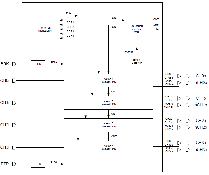
The structure of all three timers of our microcontroller is the same. Each timer has 4 channels, each of which allows you to work in the “capture” mode and PWM. We are interested in the latter. Also, each channel has exits. And 2: "direct" and inverted. We are interested in "direct". As output for outputting a PWM signal, we will use the output of the first channel of the first timer. Before moving on to the registers, let's highlight the main task: our goal is to wait some time, the timer itself changes its state at its output cyclically. - Before we start setting up the timer, we need to configure the output of the I / O port to work with the timer. I talked about how to customize the pins of the I / O ports in great detail here .
We decided to use the direct output of the first channel of the first timer.The findings have the following names.
Therefore, we need a channel TMR1_CH1.We find it.As we see, it is connected by an alternative function to the channel PA1. Despite the fact that there are more conclusions that are connected to TMR1_CH1, we will use PA1.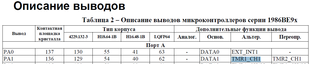
To do this, we need to apply clocking to the port (and at the same time to timer 1) and transfer the output to the alternative function mode.MDR_RST_CLK->PER_CLOCK |= RST_CLK_PCLK_TIMER1|RST_CLK_PCLK_PORTA; // A. MDR_PORTA->OE |= (1<<1); // . MDR_PORTA->FUNC |= (2<<(1*2)); // - . MDR_PORTA->ANALOG |= (1<<1); // . MDR_PORTA->PWR |= (3<<(1*2)); // . - Next, we need to allow the clock signal to be sent to the timer itself (we have already turned it on, but we didn’t give a signal from which it will count). For this there is a register MDR_RST_CLK-> TIM_CLOCK.TIM_CLOCKHere we only need to apply the clocking to the timer.
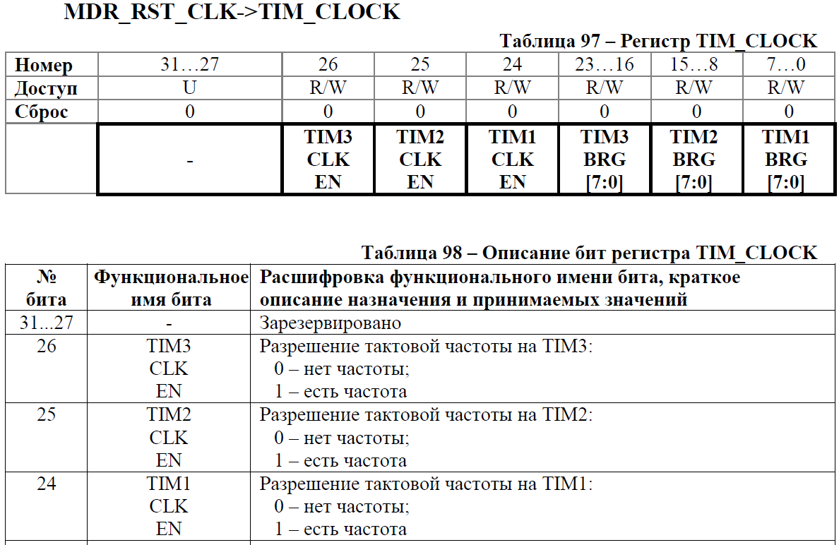
MDR_RST_CLK->TIM_CLOCK |= RST_CLK_TIM_CLOCK_TIM1_CLK_EN; // . - And now - the registers of the timer itself. Despite the fact that the timer has a lot of registers - most of them copy each other, since the structure of the control registers for each channel is the same. To begin, consider the registers of the entire timer, and then for a particular channel.
- The CNT can be called the base. It is the value in it that is compared with the “reference” one and in the event of a coincidence some action takes place. It is from him that the timer starts counting.
In our case, it is enough that it is zero. In spite of the fact that it had to be equal to zero when it was turned on, it is better to reset it just in case, since It is possible that after a software reset, the value in it will be non-zero.CNT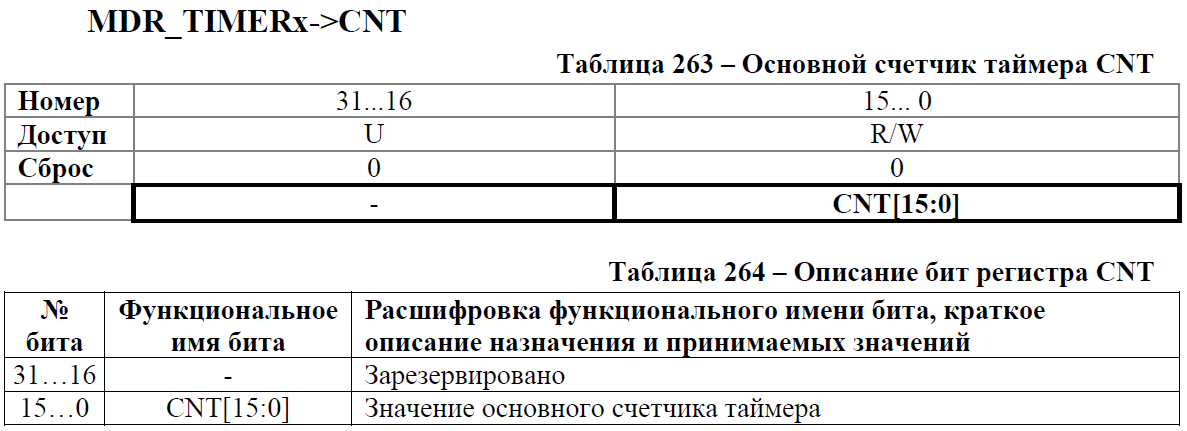
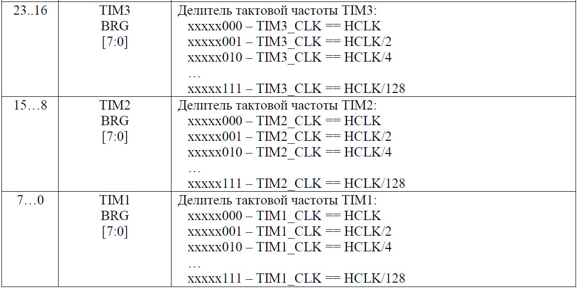
MDR_TIMER1->CNT = 0; // 0. - Psg. This register is responsible for dividing the input signal. In our case, 8000000 pulses per second are fed to the timer input (since by default the controller frequency is 8 MHz = 8000000 Hz), and we did not use dividers before the timer. As can be seen from the description, from the divider that we choose, we need to subtract 1 and put this number in the register. Since we plan to change the PWM frequency in the range from 0.5 Hz to 250 Hz (From slow blinking every 2 seconds to indistinguishable by a human eye flickering like a dim burning), then a suitable divider can be 32000. This number is in the 16-bit range numbers Thus, every 32,000 ticks in the CNT will be decreasing / decreasing (depending on the setting) unit.Psg
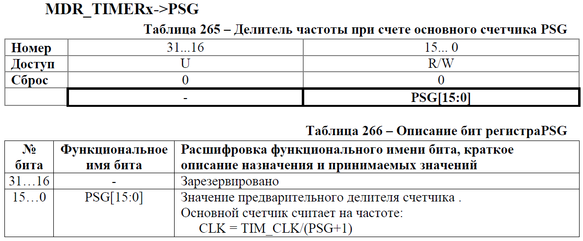
MDR_TIMER1->PSG = 32000-1; // TIM_CLK/32000. - ARR. It is with this number that the number in CNT will be compared. Since we have 250 ticks - this is one second, we will choose half of this time, so that in a second the LED has time to change its state twice. This is the number we will indicate when calling the timer initialization function.ARR
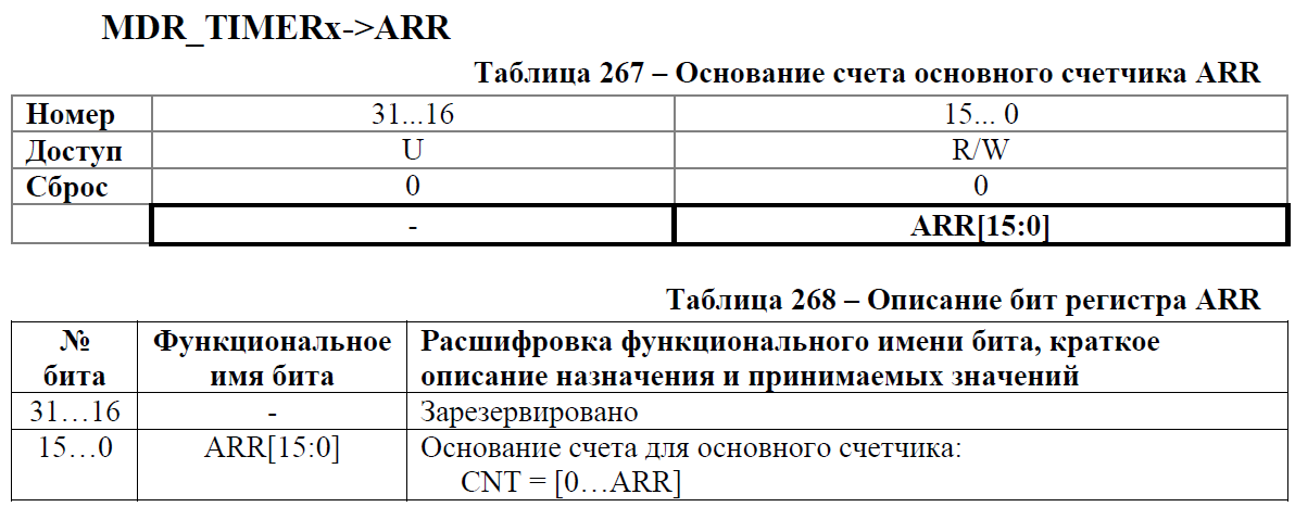
MDR_TIMER1->ARR = PWM_speed; // 1 250 . 2 . - With the general settings of the timer figured out. Can be taken for setting the signal to exit. For each channel, you can customize your signal. In our case (for the first channel), the register is CH1_CNTRL. As we agreed above, we must always have some kind of signal at the exit. Either "0" - or "1". We don’t need the “dead zone”. And we need both “0” and “1” to be equal intervals. For these purposes there is a REF signal. It can be either "1" or "0". We can also change its values whenever CNT == ARR. To do this, we need to write 0x03 (0b011) to the OCCM cell. All other parameters suit us by default.CH1_CNTRL

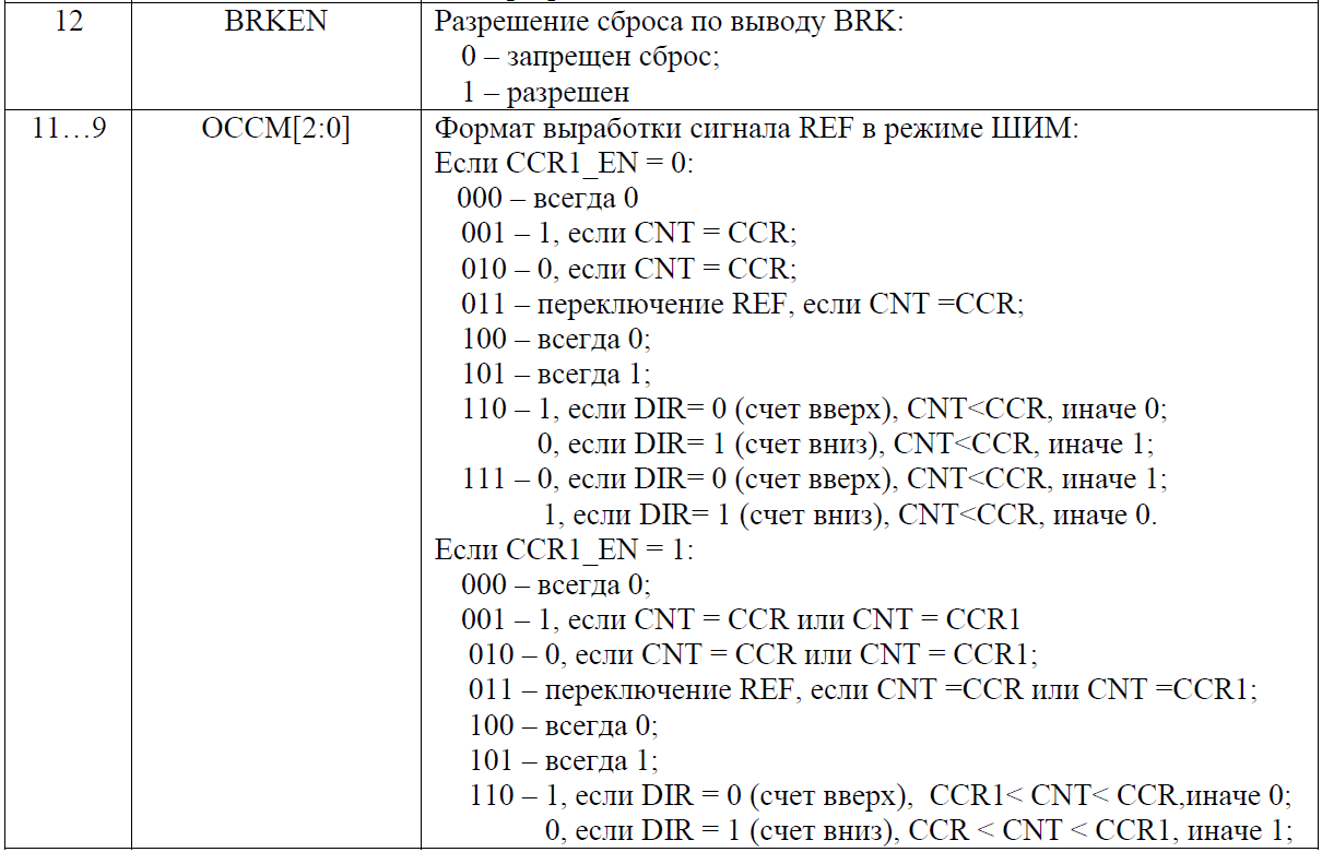

MDR_TIMER1->CH1_CNTRL = 3<<TIMER_CH_CNTRL_OCCM_Pos; // REF, CNT = CCR; - Now we need to configure the channel output. We agreed to use the first one. Here we need the register CH1_CNTRL1. We have already formed a REF signal. Now we just need to set up a “direct” output to the output and submit a REF to it. It is important not to confuse the SELO and SELOE bit groups. SELO selects which signal goes to the output, and SELOE chooses whether the output is output or not .CH1_CNTRL1
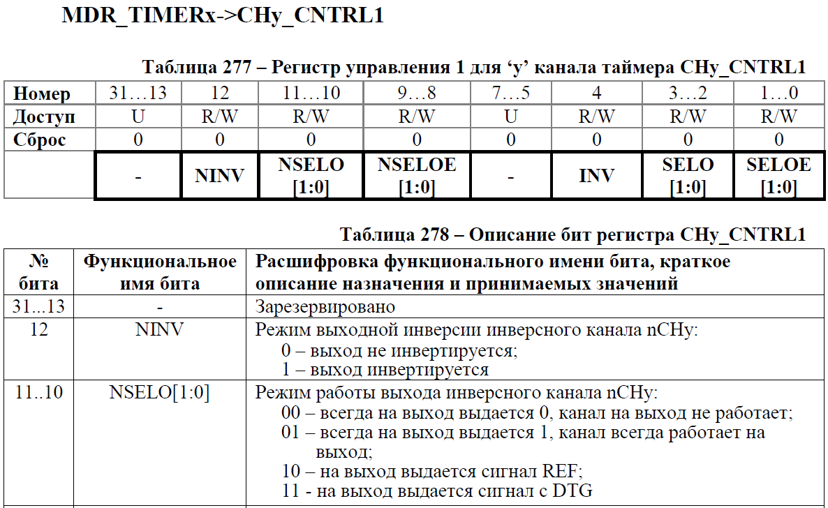
MDR_TIMER1->CH1_CNTRL1 = (2<<TIMER_CH_CNTRL1_SELO_Pos) // c REF. | (1<<TIMER_CH_CNTRL1_SELOE_Pos); // . - Now we just have to turn on the timer in the central register (I deliberately didn’t consider it before, as it should be used only after setting the entire timer).CNTRL
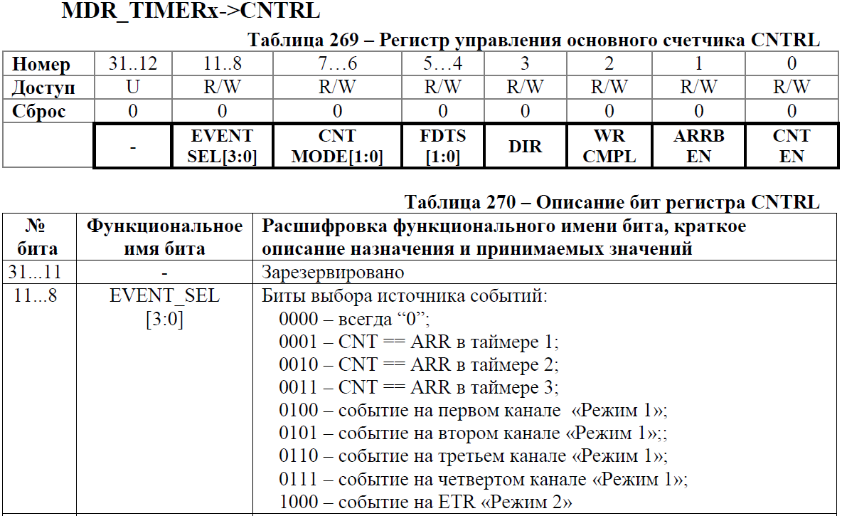


MDR_TIMER1->CNTRL = TIMER_CNTRL_CNT_EN; // . - As a result, we get a working function that initializes the timer in the PWM mode and the output, at which the logic levels oscillate.Total initialization function TIMER1
// . void initTimerPWMled (uint32_t PWM_speed) { MDR_RST_CLK->PER_CLOCK |= RST_CLK_PCLK_TIMER1|RST_CLK_PCLK_PORTA; // A. MDR_RST_CLK->TIM_CLOCK |= RST_CLK_TIM_CLOCK_TIM1_CLK_EN; // . MDR_PORTA->OE |= (1<<1); // . MDR_PORTA->FUNC |= (2<<(1*2)); // - . MDR_PORTA->ANALOG |= (1<<1); // . MDR_PORTA->PWR |= (3<<(1*2)); // . MDR_TIMER1->CNT = 0; // 0. MDR_TIMER1->PSG = 32000-1; // TIM_CLK/32000. MDR_TIMER1->ARR = PWM_speed; // 1 250 . 2 . MDR_TIMER1->CH1_CNTRL = 3<<TIMER_CH_CNTRL_OCCM_Pos; // REF, CNT = CCR; MDR_TIMER1->CH1_CNTRL1 = (2<<TIMER_CH_CNTRL1_SELO_Pos) // c REF. | (1<<TIMER_CH_CNTRL1_SELOE_Pos); // . MDR_TIMER1->CNTRL = TIMER_CNTRL_CNT_EN; // . }
- The CNT can be called the base. It is the value in it that is compared with the “reference” one and in the event of a coincidence some action takes place. It is from him that the timer starts counting.
Timer 2. Calling interrupts for polling keys, changing the PWM frequency.
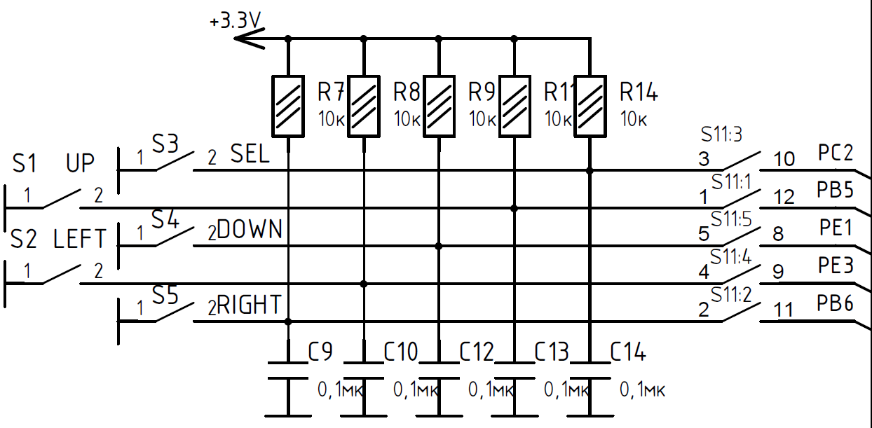
Now we are faced with the task of checking whether a key is pressed and, based on the click, change the frequency of our PWM. We will interrogate the keyboard 25 times a second and without checking released pressing. This will give us the opportunity to do a larger run-up of the PWM parameter when pressed.- Before setting the timer, we will configure the pins for all keys that are on our debug board.They are connected as follows.As we can see, the keys are connected to three different ports. Therefore, we need to configure all three ports. I note that the tightening and chattering capacitor protection is already present on the board and it is not necessary to turn on the internal tightening. We have repeatedly come up against port configuration.
 The final initialization code will look like this.Defines.
// . #define DOWN_MSK (1<<1) // PORTE #define SELECT_MSK (1<<2) // PORTC #define LEFT_MSK (1<<3) // PORTE #define UP_MSK (1<<5) // PORTB #define RIGHT_MSK (1<<6) // PORTB #define PWRMAX_UP_MSK (3<<2*5)// PORTB #define PWRMAX_RIGHT_MSK (3<<2*6) #define PWRMAX_SELECT_MSK (3<<2*2)// PORTC. #define PWRMAX_DOWN_MSK (3<<2*1)// PORTE. #define PWRMAX_LEFT_MSK (3<<2*3)
The setting function itself.// B, C, E , // . // inc . void initPinForButton (void) { MDR_RST_CLK->PER_CLOCK |= RST_CLK_PCLK_PORTB|RST_CLK_PCLK_PORTC|RST_CLK_PCLK_PORTE; // B, C, E. MDR_PORTB->OE &= ~((uint32_t)(UP_MSK|RIGHT_MSK)); // . MDR_PORTB->FUNC &= ~((uint32_t)(UP_MSK|RIGHT_MSK)); // - . MDR_PORTB->ANALOG |= UP_MSK|RIGHT_MSK; // . MDR_PORTB->PULL &= ~((uint32_t)(UP_MSK|RIGHT_MSK|UP_MSK<<16|RIGHT_MSK<<16)); // . MDR_PORTB->PD &= ~((uint32_t)(UP_MSK|RIGHT_MSK|UP_MSK<<16|RIGHT_MSK<<16)); // 200 // . MDR_PORTB->PWR |= PWRMAX_UP_MSK|PWRMAX_RIGHT_MSK; // . MDR_PORTB->GFEN |= UP_MSK|RIGHT_MSK; // ( 10 ). MDR_PORTC->OE &= ~((uint32_t)(SELECT_MSK)); // . MDR_PORTC->FUNC &= ~((uint32_t)(SELECT_MSK)); // - . MDR_PORTC->ANALOG |= SELECT_MSK; // . MDR_PORTC->PULL &= ~((uint32_t)(SELECT_MSK|SELECT_MSK<<16)); // . MDR_PORTC->PD &= ~((uint32_t)(SELECT_MSK|SELECT_MSK<<16)); // 200 . // . MDR_PORTC->PWR |= PWRMAX_SELECT_MSK; // . MDR_PORTC->GFEN |= SELECT_MSK; // ( 10 ). MDR_PORTE->OE &= ~((uint32_t)(DOWN_MSK|LEFT_MSK)); // . MDR_PORTE->FUNC &= ~((uint32_t)(DOWN_MSK|LEFT_MSK)); // - . MDR_PORTE->ANALOG |= DOWN_MSK|LEFT_MSK; // . MDR_PORTE->PULL &= ~((uint32_t)(DOWN_MSK|LEFT_MSK|DOWN_MSK<<16|LEFT_MSK<<16)); // . MDR_PORTE->PD &= ~((uint32_t)(DOWN_MSK|LEFT_MSK|DOWN_MSK<<16|LEFT_MSK<<16)); // 200 . // . MDR_PORTE->PWR |= PWRMAX_DOWN_MSK|PWRMAX_LEFT_MSK; // . MDR_PORTE->GFEN |= DOWN_MSK|LEFT_MSK; // ( 10 ). } - Since all timers have the same structure, the setting of the second timer until a certain point will be identical to the setting of the previous one. Also create a function that will initialize the timer.I have it looks like this.
// 25 . void initTimerButtonCheck (void) { } - Then everything is like in the first timer, only ARR is not 125 (half a second), but 10 (1 / 25th).Filling registers.
MDR_RST_CLK->PER_CLOCK |= RST_CLK_PCLK_TIMER2; // 2. MDR_RST_CLK->TIM_CLOCK |= RST_CLK_TIM_CLOCK_TIM2_CLK_EN; // . MDR_TIMER2->CNT = 0;// 0. MDR_TIMER2->PSG = 32000-1; // TIM_CLK/32000. MDR_TIMER2->ARR = 10; // 1 250 . 25 => 250/25=10. - Next, we need to have an interrupt when we match the CNT and ARR. For this we need a register of IE. Of the variety of different cases causing an interruption, we need the simplest one: CNT_ARR_EVENT_IE.IE


MDR_TIMER2->IE = TIMER_IE_CNT_ARR_EVENT_IE; // CNT ARR. - Now with CNT == ARR, we have an interrupt. But it will not give us anything, because by default interrupts from the entire timer are prohibited. You can fix this by enabling an interrupt from the entire timer in the NVIC controller. In previous articles we have already dealt with it. But then we flashed it in passing. In order to enable or disable interrupts, CMSIS has its own functions. You should not be afraid of them, because they are simple macros in one SI-command. But they are great at improving code readability.Here are some CMSIS commands we can use.From here, we need the NVIC_EnableIRQ function.
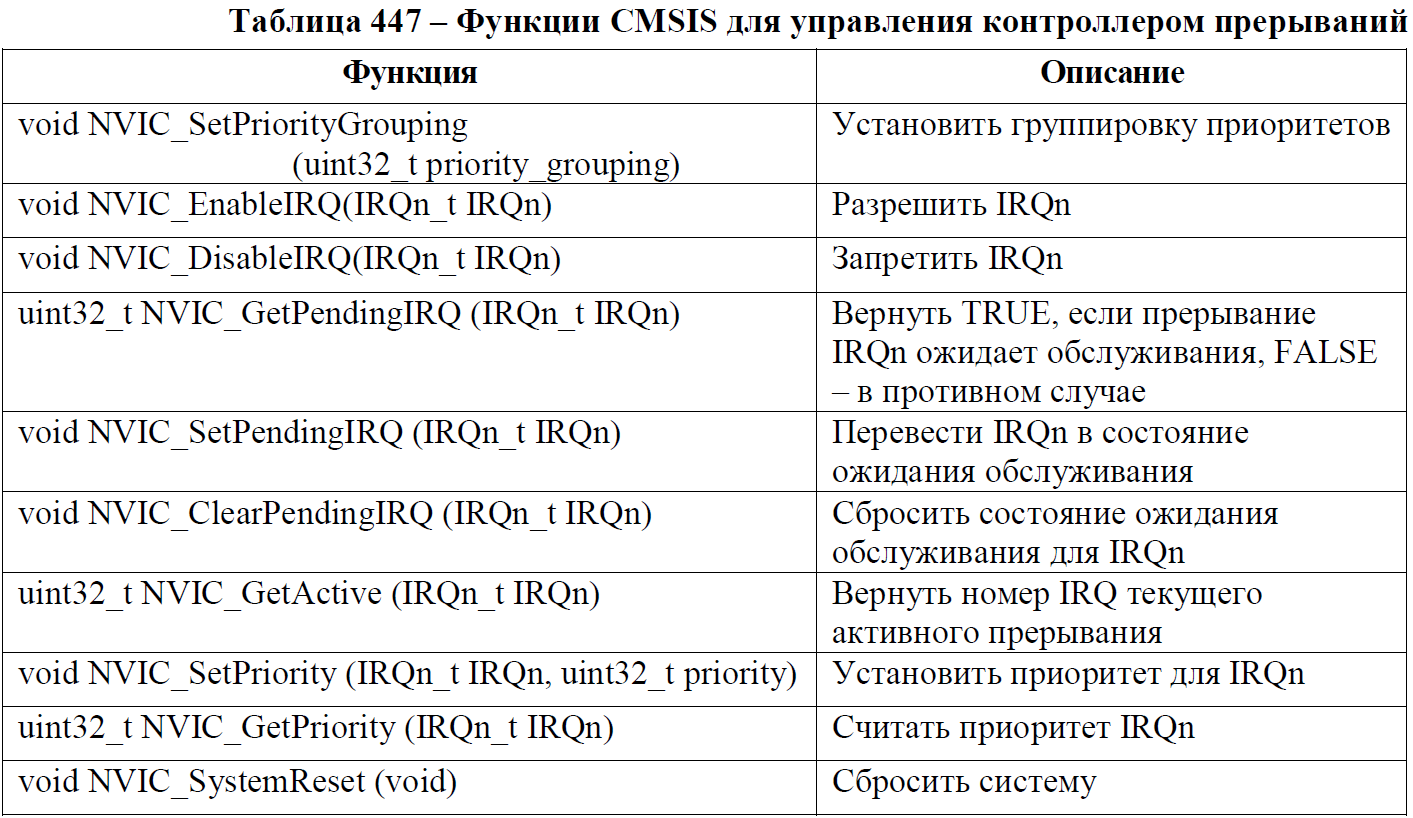 Its parameter can be obtained from the table in the file MDR32Fx.h
/* MDR32Fx Interrupt Number Definition */ typedef enum IRQn { /*---- Cortex-M3 Processor Exceptions Numbers --------------------------------*/ NonMaskableInt_IRQn = -14, /*!< 2 Non Maskable Interrupt *///!< NonMaskableInt_IRQn HardFault_IRQn = -13, /*!< 3 Hard Fault Interrupt *///!< HardFault_IRQn MemoryManagement_IRQn = -12, /*!< 4 Memory Management Interrupt *///!< MemoryManagement_IRQn BusFault_IRQn = -11, /*!< 5 Bus Fault Interrupt *///!< BusFault_IRQn UsageFault_IRQn = -10, /*!< 6 Usage Fault Interrupt *///!< UsageFault_IRQn SVCall_IRQn = -5, /*!< 11 SV Call Interrupt *///!< SVCall_IRQn PendSV_IRQn = -2, /*!< 14 Pend SV Interrupt *///!< PendSV_IRQn SysTick_IRQn = -1, /*!< 15 System Tick Timer Interrupt *///!< SysTick_IRQn /*---- MDR32Fx specific Interrupt Numbers ------------------------------------*/ CAN1_IRQn = 0, /*!< CAN1 Interrupt *///!< CAN1_IRQn CAN2_IRQn = 1, /*!< CAN1 Interrupt *///!< CAN2_IRQn USB_IRQn = 2, /*!< USB Host Interrupt *///!< USB_IRQn DMA_IRQn = 5, /*!< DMA Interrupt *///!< DMA_IRQn UART1_IRQn = 6, /*!< UART1 Interrupt *///!< UART1_IRQn UART2_IRQn = 7, /*!< UART2 Interrupt *///!< UART2_IRQn SSP1_IRQn = 8, /*!< SSP1 Interrupt *///!< SSP1_IRQn I2C_IRQn = 10, /*!< I2C Interrupt *///!< I2C_IRQn POWER_IRQn = 11, /*!< POWER Detecor Interrupt *///!< POWER_IRQn WWDG_IRQn = 12, /*!< Window Watchdog Interrupt *///!< WWDG_IRQn Timer1_IRQn = 14, /*!< Timer1 Interrupt *///!< Timer1_IRQn Timer2_IRQn = 15, /*!< Timer2 Interrupt *///!< Timer2_IRQn Timer3_IRQn = 16, /*!< Timer3 Interrupt *///!< Timer3_IRQn ADC_IRQn = 17, /*!< ADC Interrupt *///!< ADC_IRQn COMPARATOR_IRQn = 19, /*!< COMPARATOR Interrupt *///!< COMPARATOR_IRQn SSP2_IRQn = 20, /*!< SSP2 Interrupt *///!< SSP2_IRQn BACKUP_IRQn = 27, /*!< BACKUP Interrupt *///!< BACKUP_IRQn EXT_INT1_IRQn = 28, /*!< EXT_INT1 Interrupt *///!< EXT_INT1_IRQn EXT_INT2_IRQn = 29, /*!< EXT_INT2 Interrupt *///!< EXT_INT2_IRQn EXT_INT3_IRQn = 30, /*!< EXT_INT3 Interrupt *///!< EXT_INT3_IRQn EXT_INT4_IRQn = 31 /*!< EXT_INT4 Interrupt *///!< EXT_INT4_IRQn }IRQn_Type;
We need a second timer. Therefore, our function will look like this.NVIC_EnableIRQ(Timer2_IRQn); // . - It remains only to enable the timer and our final function will be as follows.Initialize timer 2 to poll buttons.// Set the timer to generate interrupts 25 times per second.
void initTimerButtonCheck (void)
{
MDR_RST_CLK-> PER_CLOCK | = RST_CLK_PCLK_TIMER2; // Enable timer clocking 2.
MDR_RST_CLK-> TIM_CLOCK | = RST_CLK_TIM_CLOCK_TIM2_CLK_EN; // Feed clocking without a prescaler.
MDR_TIMER2-> CNT = 0; // Count with 0.
MDR_TIMER2-> PSG = 32000-1; // The timer TIM_CLK / 32000 goes to the timer.
MDR_TIMER2-> ARR = 10; // 1 second 250 ticks. We have 25 polls per second => 250/25 = 10.
MDR_TIMER2-> IE = TIMER_IE_CNT_ARR_EVENT_IE; // Allow the interrupt on the combination of CNT and ARR.
NVIC_EnableIRQ (Timer2_IRQn); // Enable interrupt from the timer as a whole.
MDR_TIMER2-> CNTRL = TIMER_CNTRL_CNT_EN; // Turn on the timer.
} - Now we need to create an interrupt handler. His name is strictly fixed in the startup_MDR32F9Qx.s file. There is only one interrupt vector for the entire timer. All the names there are intuitive. Ours is called Timer2_IRQHandler. Create a function with empty input parameters. And the first team needs to reset the interrupt flag, because of which we got here. Otherwise, after exiting the interrupt, we will get back to its beginning. It is also impossible to drop the flag at the end, because there is not enough time for it to be “completely reset” and as a result we still fall into the interruption with the flag not thrown. It is imperative that before exiting an interrupt there is at least one command dividing flag reset and exiting interrupt. You can reset the flag in the register STATUS.STATUSSince we have only one event from the timer used, we can safely write "0" in the entire register. If we didn’t have several events, we would have to first check which event occurred. In our case, the function will be as follows.
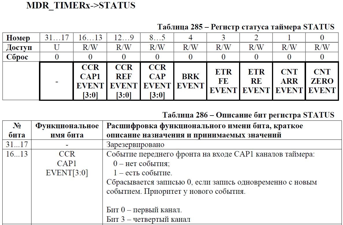
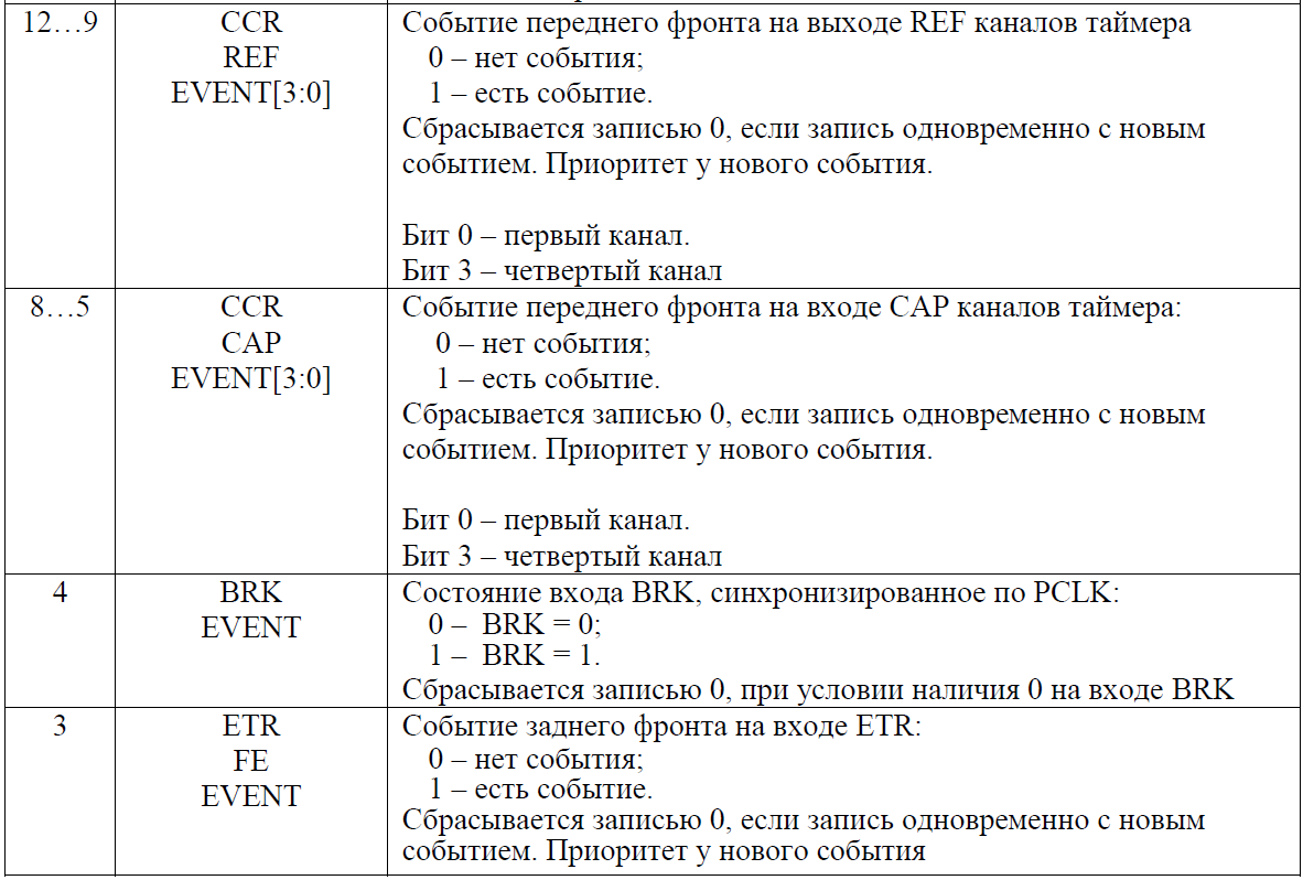
void Timer2_IRQHandler (void) { MDR_TIMER2->STATUS = 0; // . . // . } - At the very beginning of the article, we decided that when entering an interrupt, we would change the state of the LED to show that the interrupt had been processed. To do this, we need to use one of two custom LEDs connected to PC0 and PC1 pins.Connecting LEDs.I suggest using PC0 for this purpose (on the board it’s on the left). And the LED connected to PC1 must be disconnected from the output of the microcontroller and connected with a wire to PA1 (our PWM pin).
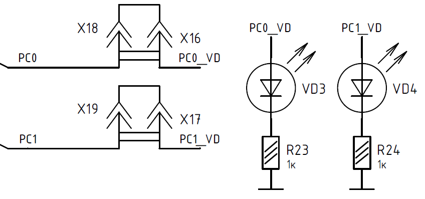 The initialization of the LEDs will look like this.The function adjusts both LEDs, but since the second is disconnected (jumper), then there will be no difference.
// . #define LED0 (1<<0) // PORTC. #define LED1 (1<<1) // PORTC. #define PWRMAX_LED0 (3<<2*0) // . #define PWRMAX_LED1 (3<<2*1) // C . void initPinPortCForLed (void) { MDR_RST_CLK->PER_CLOCK |= RST_CLK_PCLK_PORTC; // C. MDR_PORTC->OE |= LED0|LED1; // . MDR_PORTC->FUNC &= ~((uint32_t)(LED0|LED1)); // - . MDR_PORTC->ANALOG |= LED0|LED1; // . MDR_PORTC->PULL &= ~((uint32_t)(LED0|LED1|LED0<<16|LED1<<16)); // . MDR_PORTC->PD &= ~((uint32_t)(LED0|LED1|LED0<<16|LED1<<16)); // 200 . // . MDR_PORTC->PWR |= PWRMAX_LED0|PWRMAX_LED1; // . MDR_PORTC->GFEN &= ~((uint32_t)(LED0|LED1)); // . } - It remains only to poll the keys and change the value in the ARR PWM timer. But our buttons are connected to the 3rd different ports. You can, of course, the old-fashioned way. Take the values from the whole port and use the mask to look at specific conclusions, but in this case it is much more convenient to use BitBanding. If we don’t go into details, then each bit of the peripheral area (including I / O ports) has its own 32-bit cell. In which either "1" or "0" is written. Depending on the state of the bit. You can work with them as with ordinary registers. The entry "1" will give 1 in the desired bit of the real register. “0” is respectively 0. In order to get the addresses of these cells, you can use the very convenient Catethysis calculator. Let us consider an example. We have a UP key connected to pin 5 of port B. Go to the documentation and look at the address of the port register B.We find thereWe drive in this address in the “register” field, and in the “bit” field we write 5. At the output we get 0x43600014. Working with a cell at this address, we are working with bit 5 of port B. But it is impossible to simply write 0x43600014 = 1. But * (uint32_t *) 0x43600014 = 1 - you can.
 Now, in this way you can rewrite all the pins connected to the buttons.Similarly, you can do for the LED.
// . #define DOWN_FLAG *(uint32_t*)0x43900004 #define SELECT_FLAG *(uint32_t*)0x43700008 #define LEFT_FLAG *(uint32_t*)0x4390000c #define UP_FLAG *(uint32_t*)0x43600014 #define RIGHT_FLAG *(uint32_t*)0x43600018#define LED0_FLAG *(uint32_t*)0x43700000 - Now it remains only to record a poll of the buttons and a change in the ARR register of timer 1.The final function will look like this.int PWM_speed = 125;
void Timer2_IRQHandler (void)
{
MDR_TIMER2-> STATUS = 0; // Reset the flag. Be sure to be the first team.
LED1_FLAG =! LED1_FLAG; // Show that the interrupt was handled.
if (UP_FLAG == 0) PWM_speed--; // Check if any key is pressed. If pressed, we do something with frequency.
else if (DOWN_FLAG == 0) PWM_speed ++;
else if (LEFT_FLAG == 0) PWM_speed--;
else if (RIGHT_FLAG == 0) PWM_speed ++;
if (PWM_speed <1) PWM_speed = 1; // Check that the frequency does not go beyond the range from 250 Hz to 0.5 Hz.
else if (PWM_speed> 500) PWM_speed = 500;
MDR_TIMER1-> ARR = PWM_speed; // Change the frequency.
} - The main main function contains only an enumeration of all the above functions.Looks like that.int main (void)
{
initTimerPWMled (PWM_speed); // Run PWM. Parameter - PWM speed.
initPinForButton (); // Customize the buttons.
initPinPortCForLed (); // LED operation (key read).
initTimerButtonCheck (); // Initialize the timer.
while (1)
{
}
}
Instead of conclusion
In this article we reviewed the implementation of the task without using the SPL library. In the next article, we will accomplish the same task, but using only SPL and compare the results.
The final project.
Small addition
At the moment, Milandr has released a new, revised version of SPL. Unfortunately, not yet in the form of a full version. In the current version, you cannot view the status of registers in keil windows. But soon the full version will be released and this flaw will be fixed. For those who want to try the new version - here is a link to a clean project .
Who needs windows - can still use the stable old .
List of previous articles.
- 1. We turn from STM32F103 to K1986BE92QI. Or the first acquaintance with the Russian microcontroller.
- 2. We are switching from STM32 to the Russian K1986BE92QI microcontroller. Setup project in keil and flashing LED.
- 3. We are switching from STM32 to the Russian K1986BE92QI microcontroller. System Timer (SysTick).
- 4. We are switching from STM32 to the Russian K1986BE92QI microcontroller. Setting the clock frequency.
- 5. We are switching from STM32 to the Russian K1986BE92QI microcontroller. Practical application: Generate and reproduce sound. Part one: we generate a square and sinusoidal signal. Mastering the DAC (DAC).
- 6. We are switching from STM32 to the Russian K1986BE92QI microcontroller. Practical application: Generate and reproduce sound. Part two: generate a sinusoidal signal. Mastering DMA.
- 7. We are switching from STM32 to the Russian K1986BE92QI microcontroller. Practical application: Generate and reproduce sound. Part three: generate a sine wave. A simple look at DMA + first acquaintance with timers.
- 8. We are switching from STM32 to the Russian K1986BE92QI microcontroller. Practical application: Generate and reproduce sound. Part Four: we create the digital part of a single-voiced and multi-voiced musical postcard.
Source: https://habr.com/ru/post/267051/
All Articles