Implementing a pseudo-random number generator on a FPGA using Vivado HLS 2014.4
In many problems it becomes necessary to use a pseudo-random number generator. So we have such a need. In general, the task was to create a computing platform based on the RB8V7 unit, which was supposed to be used as an accelerator of calculations for a specific scientific task.
I will say a few words about this scientific problem: it was necessary to calculate the dynamics of biological microtubules at times of the order of a minute. The calculations were calculations using a molecular-mechanical model of a microtubule developed in a scientific group. It was planned that, based on the results of the calculations, it would be possible to conclude about the mechanisms of dynamic instability of microtubules. The need to use an accelerator was due to the fact that a minute is equivalent to a sufficiently large number of calculation steps (~ 10 ^ 12) and, as a result, to a large amount of time spent on calculations.
So, returning to the topic of the article, in our case, pseudo-random number generators were needed to take into account the thermal motion of the molecules of the microtubules mentioned.
')
As the basic architecture of the project was used architecture with support for DMA transmissions . As a component of this computing platform, it was necessary to implement an IP core that would be able to generate a new pseudo-random, normally distributed float number every clock cycle and use as few resources as possible on the FPGA.
I want to note that, as a result, everything turned out well for us, but the path to solving this problem was not without wrong steps and mistakes, which I also want to write below. I hope this article will be useful.
To solve this problem, we used a high-level language translator in RTL code. To implement a complex computational problem, this approach allows one to obtain a result much faster (and often better) than using bare RTL. We used the Vivado HLS version 2014.4 program, which translates C / C ++ code using special directives into RTL code. Examples of directives can be found here .
Taking into account the mentioned requirements for the solution being developed and the fact that the generator must include several stages of calculation, the most suitable architecture is a pipeline. You can read more about the implementation of the FPGA conveyor here . I want to note that the main characteristics of the computing pipeline are the initialization interval and latency. The initialization interval is the number of cycles spent on the execution of the conveyor stage (the maximum among all the stages).
Latency is the number of ticks elapsed from the moment the data arrived at the input of the pipeline until the result of the conveyor output. In this case, the latency does not interest us very much, since it is negligible compared to the estimated total time of the pipeline, but the initialization interval should be taken very carefully, because it actually characterizes how often the pipeline is able to accept data and how often he is able to produce a new result.
Initially, it was decided to use the following approach:
From the advantages of this approach, it is worth noting that this generator of normal numbers is implemented in the final scheme very simply and doesn’t really take very much. The main disadvantage of this approach is that it is wrong in our case. =) Indeed, the sequential values that the generator produces are correlated. This can be clearly demonstrated by building an autocorrelation function (see fig.), Or by plotting x [i + k] as a function of x [i], where k = 1,2,3 ...
This error resulted in interesting effects in the dynamics of microtubules, the movement of which was modeled using this generator.

So, the algorithm for generating uniformly distributed integers needed to be changed. The choice fell on the Mersenne Whirlwind . The fact that the algorithm values of the generated numbers are not correlated with each other can be seen by looking at the autocorrelation function of the resulting sequence of numbers. However, the implementation of this algorithm requires more resources, since it works with a field of numbers of size 612, rather than with one number as in the previous case (see the code in the public domain ).
Immediately make a reservation that I understand by the words "the procedure takes n cycles (steps)." This means that this procedure, when broadcasting in RTL, will be performed in n clock pulses. For example, if at the next step of the pipeline we need to read two words from a single-port RAM memory, then this operation will be performed in two cycles, since the port is only one, that is, the memory can ensure that only one write or read request is executed per clock.
For optimal translation of this algorithm in RTL code it was necessary to rework. First, in the initial implementation inside the generator, the following happens: when a new random number is requested, either the next matrix element is output, or when the matrix end is reached, the matrix elements are updated. The update procedure consists of various bitwise operations using array elements. The procedure takes at least 612 steps, since the value of each element is updated. Then the output is the zero element of the matrix. Thus, the procedure will take a different number of steps for different calls to this function. Such a function cannot be pipelined.
Let's change this procedure: now, in one call to the function, the previous element of the array is updated and the current element is returned. Now this procedure always takes the same number of cycles. At the same time, the result is the same in both implementations: at the end of the matrix traversal, it will already be filled with the updated values and you can simply return to the zero element of the array. Now this procedure is really pipelined.
Now let us ask ourselves how often such a pipeline will be able to produce a new random number? For this we need to add some extra clarity. What resources should the array be used with (mt)? It can be implemented either using registers or using memory. Implementation using registers is the easiest from the point of view of the final code optimization to achieve a single initialization interval. Unlike memory cells, each register can be accessed independently.
However, in the case of using a large number of registers, there is a high probability of time delays on the paths between the registers, which leads to the need to reduce the operating frequency for the generated IP core. In the case of memory use, there is a limit on the number of simultaneous requests to a memory block, the cause of which is the limited number of block ports. However, problems with time delays, as a rule, do not arise. Due to resource constraints in our case, it would be preferable to implement an array using memory. Consider whether we have access memory conflicts and whether it is possible to resolve them.
So, how many simultaneous from the point of view of FPGA are array element requests occurring per clock? First, we note that at every clock cycle we work with four cells of the array. That is, in the first approximation, we need to provide four simultaneous requests to the memory: three reads and one write. Moreover, one read and one write occur in the same cell.
The first problem that needs to be solved is to remove the read / write conflict in the same cell. This can be done by noting that, as a result of successive calls to a function, it is just reading from the same cell, thus, for the previous call, it is enough to read the value and save the read in the register, and the next one just take the necessary number from the register. Now it is necessary to provide three simultaneous requests to the memory: two reads and one write (in different memory cells).
There are several techniques for resolving memory requests conflicts in Vivado HLS: first, add a directive that tells the translator to implement an array through dual-port RAM memory, so you can afford two simultaneous requests to the memory block, provided that they do not access to the same cell.
Secondly, there is a directive that tells the translator to implement an array not through one block of memory, but through several. This can increase the total number of ports, and thus increase the maximum possible number of simultaneous requests. For example, it is possible to make so that the elements of an array with indices 0 ... N / 2 lay in one memory block, and the elements with indices N / 2 + 1 ... N-1 lay in the second memory block. Or, for example, elements with indices 2 * k lay in one block, and elements with indices 2 * k + 1 lay in another block. I note that the number of blocks may be> 2. It also allows in some cases to increase the number of possible simultaneous requests to the array.
Unfortunately, the latter approach in our case was not applicable in its pure form, since we had to split our array into several blocks of unequal size, which the directive does not know how to do. If you carefully look at which elements in the array are accessed during the passage through all indexes, you can see that the array can be divided into three parts so that each part has no more than two simultaneous queries.

In fact, this stage took the greatest amount of time, since the Vivado HLS translator stubbornly did not want to understand what we wanted from it and the final initialization interval was more than 1. It helped that we just presented and drew the final scheme and wrote it in accordance with it code. Earned!
Thus, we implemented our array through 3 blocks of dual-port RAM memory, which allowed us to pipe our function and provide a single initialization interval. That is, now we have a working generator of uniformly distributed pseudo-random numbers. Now you need to get from these numbers normally distributed pseudo-random numbers. One could take advantage of the previous approach using the central limit theorem. However, I remind you that now the generator of uniformly distributed random numbers takes up much more resources, and for the central limit theorem, it would be necessary to implement 12 such generators.
Our choice fell on the Box-Muller transformation , which allows us to obtain two normally distributed random numbers from two uniformly distributed random variables on the segment (0.1]. And unlike the approach with the CLT, where 12 is actually not a very large number, in the case of a transformation, we get numbers for which the distribution is analytically exactly Gaussian. A little more detail can be found here . I just want to note that this transformation exists in two versions: one uses less computation, but This result is not given every time the generator is called, the second approach uses more calculations, but the result is guaranteed with each call.
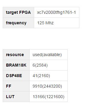
As a result, we need every measure, a second hike was used. In addition, a directive was applied to each computational operation, which instructs the translator to NOT implement this operation using DSP blocks. By default, Vivado HLS implements computational operations using the maximum number of DSP blocks. The fact is that, taking into account pipelining, the number of necessary DSP blocks would be quite large compared to the total number of available DSP blocks. Considering their location on the chip, long time delays would have been obtained.
As a result, we got a kernel using the following hike:
I also bring in a visualization of the microtubule dynamics using this generator.
PS: In fact, after it turned out that the use of the “Mersenne Vortex” approach + the Box-Muller transformation is indeed a working approach for obtaining normally distributed random numbers [1].
The project is available on github .
I welcome any questions or comments.
[1] High-Performance Computing Using FPGAs Editors: Vanderbauwhede, Wim, Benkrid, Khaled (Eds.) 2013 pp. 20-30
I will say a few words about this scientific problem: it was necessary to calculate the dynamics of biological microtubules at times of the order of a minute. The calculations were calculations using a molecular-mechanical model of a microtubule developed in a scientific group. It was planned that, based on the results of the calculations, it would be possible to conclude about the mechanisms of dynamic instability of microtubules. The need to use an accelerator was due to the fact that a minute is equivalent to a sufficiently large number of calculation steps (~ 10 ^ 12) and, as a result, to a large amount of time spent on calculations.
So, returning to the topic of the article, in our case, pseudo-random number generators were needed to take into account the thermal motion of the molecules of the microtubules mentioned.
')
As the basic architecture of the project was used architecture with support for DMA transmissions . As a component of this computing platform, it was necessary to implement an IP core that would be able to generate a new pseudo-random, normally distributed float number every clock cycle and use as few resources as possible on the FPGA.
Read more
The last requirement was due to the fact that, first of all, apart from this IP core, other computational modules + interface part had to be present on the FPGA, secondly, calculations in the task were performed on floating-point numbers of the float type, which in the case of FPGAs occupy quite a lot of resources, and, thirdly, several cores were assumed on FPGAs. The requirement to generate a random number every clock was due to the architecture of the final computing module, which, in fact, used the data random numbers. The architecture was a pipeline and, accordingly, required new random numbers every clock.
I want to note that, as a result, everything turned out well for us, but the path to solving this problem was not without wrong steps and mistakes, which I also want to write below. I hope this article will be useful.
To solve this problem, we used a high-level language translator in RTL code. To implement a complex computational problem, this approach allows one to obtain a result much faster (and often better) than using bare RTL. We used the Vivado HLS version 2014.4 program, which translates C / C ++ code using special directives into RTL code. Examples of directives can be found here .
Taking into account the mentioned requirements for the solution being developed and the fact that the generator must include several stages of calculation, the most suitable architecture is a pipeline. You can read more about the implementation of the FPGA conveyor here . I want to note that the main characteristics of the computing pipeline are the initialization interval and latency. The initialization interval is the number of cycles spent on the execution of the conveyor stage (the maximum among all the stages).
Latency is the number of ticks elapsed from the moment the data arrived at the input of the pipeline until the result of the conveyor output. In this case, the latency does not interest us very much, since it is negligible compared to the estimated total time of the pipeline, but the initialization interval should be taken very carefully, because it actually characterizes how often the pipeline is able to accept data and how often he is able to produce a new result.
Initially, it was decided to use the following approach:
- linear feedback shift registers for obtaining independent integers of uniformly distributed random numbers. In the beginning, each of them is initiated with the help of its “seed” number, the so-called seed.
- central limit theorem, which allows us to state that the sum of a large number of independent random variables has a distribution close to normal. In our case, 12 numbers are added.
Code
#pragma HLS PIPELINE unsigned lsb = lfsr & 1; lfsr >>= 1; if (lsb == 1) lfsr ^= 0x80400002; return lfsr; From the advantages of this approach, it is worth noting that this generator of normal numbers is implemented in the final scheme very simply and doesn’t really take very much. The main disadvantage of this approach is that it is wrong in our case. =) Indeed, the sequential values that the generator produces are correlated. This can be clearly demonstrated by building an autocorrelation function (see fig.), Or by plotting x [i + k] as a function of x [i], where k = 1,2,3 ...
Autocorrelation function
This error resulted in interesting effects in the dynamics of microtubules, the movement of which was modeled using this generator.
So, the algorithm for generating uniformly distributed integers needed to be changed. The choice fell on the Mersenne Whirlwind . The fact that the algorithm values of the generated numbers are not correlated with each other can be seen by looking at the autocorrelation function of the resulting sequence of numbers. However, the implementation of this algorithm requires more resources, since it works with a field of numbers of size 612, rather than with one number as in the previous case (see the code in the public domain ).
autocorrelation function
Immediately make a reservation that I understand by the words "the procedure takes n cycles (steps)." This means that this procedure, when broadcasting in RTL, will be performed in n clock pulses. For example, if at the next step of the pipeline we need to read two words from a single-port RAM memory, then this operation will be performed in two cycles, since the port is only one, that is, the memory can ensure that only one write or read request is executed per clock.
For optimal translation of this algorithm in RTL code it was necessary to rework. First, in the initial implementation inside the generator, the following happens: when a new random number is requested, either the next matrix element is output, or when the matrix end is reached, the matrix elements are updated. The update procedure consists of various bitwise operations using array elements. The procedure takes at least 612 steps, since the value of each element is updated. Then the output is the zero element of the matrix. Thus, the procedure will take a different number of steps for different calls to this function. Such a function cannot be pipelined.
Option 0
unsigned long y; if (mti >= N) { /* generate N words at one time */ int kk; if (mti == N+1) /* if sgenrand() has not been called, */ sgenrand(4357); /* a default initial seed is used */ for (kk=0;kk<NM;kk++) { y = (mt[kk]&UPPER_MASK)|(mt[kk+1]&LOWER_MASK); mt[kk] = mt[kk+M] ^ (y >> 1) ^ mag01[y & 0x1]; } for (;kk<N-1;kk++) { y = (mt[kk]&UPPER_MASK)|(mt[kk+1]&LOWER_MASK); mt[kk] = mt[kk+(MN)] ^ (y >> 1) ^ mag01[y & 0x1]; } y = (mt[N-1]&UPPER_MASK)|(mt[0]&LOWER_MASK); mt[N-1] = mt[M-1] ^ (y >> 1) ^ mag01[y & 0x1]; mti = 0; } y = mt[mti++]; y ^= (y >> 11); y ^= (y << 7) & 0x9d2c5680UL; y ^= (y << 15) & 0xefc60000UL; y ^= (y >> 18); return ( (double)y * 2.3283064370807974e-10 ); /* reals */ /* return y; */ /* for integer generation */ Let's change this procedure: now, in one call to the function, the previous element of the array is updated and the current element is returned. Now this procedure always takes the same number of cycles. At the same time, the result is the same in both implementations: at the end of the matrix traversal, it will already be filled with the updated values and you can simply return to the zero element of the array. Now this procedure is really pipelined.
Option 1
#pragma HLS PIPELINE #pragma HLS INLINE float y; unsigned long mt_temp,reg1; unsigned long temper, temper1; if (mti<N_period-M_period) { mt_temp = (mt[mti]&UPPER_MASK)|(mt[mti+1]&LOWER_MASK); mt[mti] = mt[mti+M_period] ^ (mt_temp >> 1) ^ mag01[mt_temp & 0x1UL]; }else{ if (mti<N_period-1) { mt_temp = (mt[mti]&UPPER_MASK)|(mt[mti+1]&LOWER_MASK); mt[mti] = mt[mti+(M_period-N_period)] ^ (mt_temp >> 1) ^ mag01[mt_temp & 0x1UL]; }else{ mt_temp = (mt[N_period-1]&UPPER_MASK)|(mt[0]&LOWER_MASK); mt[N_period-1] = mt[M_period-1] ^ (mt_temp >> 1) ^ mag01[mt_temp & 0x1UL]; } } reg1 = mt[mti]; if (mti == (N_period - 1)) mti = 0; else mti=mti+1; temper=tempering(reg1); temper1 = (temper==0) ? 1 : temper; y=(float) temper1/4294967296.0; return y; Now let us ask ourselves how often such a pipeline will be able to produce a new random number? For this we need to add some extra clarity. What resources should the array be used with (mt)? It can be implemented either using registers or using memory. Implementation using registers is the easiest from the point of view of the final code optimization to achieve a single initialization interval. Unlike memory cells, each register can be accessed independently.
However, in the case of using a large number of registers, there is a high probability of time delays on the paths between the registers, which leads to the need to reduce the operating frequency for the generated IP core. In the case of memory use, there is a limit on the number of simultaneous requests to a memory block, the cause of which is the limited number of block ports. However, problems with time delays, as a rule, do not arise. Due to resource constraints in our case, it would be preferable to implement an array using memory. Consider whether we have access memory conflicts and whether it is possible to resolve them.
So, how many simultaneous from the point of view of FPGA are array element requests occurring per clock? First, we note that at every clock cycle we work with four cells of the array. That is, in the first approximation, we need to provide four simultaneous requests to the memory: three reads and one write. Moreover, one read and one write occur in the same cell.
Option 2
#pragma HLS PIPELINE #pragma HLS INLINE float y; unsigned long mt_temp,reg1,reg2,reg3,result; unsigned long temper, temper1; if (mti<N_period-M_period) { reg2=mt[mti+1]; // read 0 reg3=mt[mti+M_period]; // read 1 }else{ if (mti<N_period-1) { reg2=mt[mti+1]; //read 0 reg3=mt[mti+(M_period-N_period)]; //read 1 }else{ reg2=mt[0]; //read 0 reg3=mt[M_period-1]; //read 1 } } reg1 = mt[mti]; //read 2 mt_temp = (reg1&UPPER_MASK)|(reg2&LOWER_MASK); result = reg3 ^ (mt_temp >> 1) ^ mag01[mt_temp & 0x1UL]; mt[mti]=result; //write if (mti == (N_period - 1)) mti = 0; else mti=mti+1; temper=tempering(result); temper1 = (temper==0) ? 1 : temper; y=(float) temper1/4294967296.0; return y; The first problem that needs to be solved is to remove the read / write conflict in the same cell. This can be done by noting that, as a result of successive calls to a function, it is just reading from the same cell, thus, for the previous call, it is enough to read the value and save the read in the register, and the next one just take the necessary number from the register. Now it is necessary to provide three simultaneous requests to the memory: two reads and one write (in different memory cells).
Option 3
#pragma HLS PIPELINE #pragma HLS INLINE float y; unsigned long mt_temp,reg1,reg2,reg3,result; unsigned long temper, temper1; if (mti<N_period-M_period) { reg2=mt[mti+1]; //read 0 reg3=mt[mti+M_period]; //read1 }else{ if (mti<N_period-1) { reg2=mt[mti+1]; //read 0 reg3=mt[mti+(M_period-N_period)]; //read 1 }else{ reg2=mt[0]; //read 0 reg3=mt[M_period-1]; //read 1 } } reg1 = prev_val; mt_temp = (reg1&UPPER_MASK)|(reg2&LOWER_MASK); result = reg3 ^ (mt_temp >> 1) ^ mag01[mt_temp & 0x1UL]; mt[mti]=result; //write prev_val=reg2; if (mti == (N_period - 1)) mti = 0; else mti=mti+1; temper=tempering(result); temper1 = (temper==0) ? 1 : temper; y=(float) temper1/4294967296.0; return y; There are several techniques for resolving memory requests conflicts in Vivado HLS: first, add a directive that tells the translator to implement an array through dual-port RAM memory, so you can afford two simultaneous requests to the memory block, provided that they do not access to the same cell.
#pragma HLS RESOURCE variable=mt1 core=RAM_2P_BRAM Secondly, there is a directive that tells the translator to implement an array not through one block of memory, but through several. This can increase the total number of ports, and thus increase the maximum possible number of simultaneous requests. For example, it is possible to make so that the elements of an array with indices 0 ... N / 2 lay in one memory block, and the elements with indices N / 2 + 1 ... N-1 lay in the second memory block. Or, for example, elements with indices 2 * k lay in one block, and elements with indices 2 * k + 1 lay in another block. I note that the number of blocks may be> 2. It also allows in some cases to increase the number of possible simultaneous requests to the array.
#pragma HLS array_partition variable=AB block factor=4 Unfortunately, the latter approach in our case was not applicable in its pure form, since we had to split our array into several blocks of unequal size, which the directive does not know how to do. If you carefully look at which elements in the array are accessed during the passage through all indexes, you can see that the array can be divided into three parts so that each part has no more than two simultaneous queries.
In fact, this stage took the greatest amount of time, since the Vivado HLS translator stubbornly did not want to understand what we wanted from it and the final initialization interval was more than 1. It helped that we just presented and drew the final scheme and wrote it in accordance with it code. Earned!
Scheme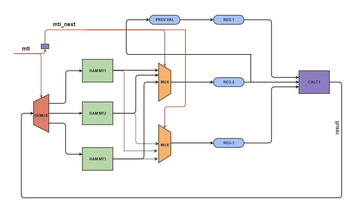
Final version
#pragma HLS PIPELINE #pragma HLS RESOURCE variable=mt1 core=RAM_2P_BRAM #pragma HLS RESOURCE variable=mt2 core=RAM_2P_BRAM #pragma HLS RESOURCE variable=mt3 core=RAM_2P_BRAM #pragma HLS INLINE float y; unsigned long mt_temp,reg1,reg2,reg3,result, m1_temp,m2_temp, m3_temp; unsigned long temper, temper1; unsigned int a1,a2, a3,s2,s3; int mti_next=0; if (mti == (N_period - 1)) mti_next = 0; else mti_next=mti+1; if (mti_next==0) { s2=1; s3=2; a1=mti_next; a2=2*M_period-N_period-1; a3=0; } else if (mti_next < (N_period - M_period)) { s2 = 1; s3 = 3; a1 = mti_next; a2 = 0; a3 = mti_next-1; }else if (mti_next== (N_period - M_period)){ s2 = 2; s3 = 3; a2 = 0; a1 = 0; a3 = N_period-M_period-1; } else if (mti_next < M_period) { s2 = 2; s3 = 1; a1 = mti_next - (N_period - M_period)-1; a2 = mti_next - (N_period - M_period); a3 = 0; } else if (mti_next < (2*(N_period-M_period)+1)) { s2 = 3; s3 = 1; a1 = mti_next - (N_period - M_period)-1; a2 = 0; a3 = mti_next - M_period; } else { s2 = 3; s3 = 2; a1 = 0; a2 = mti_next - (2*(N_period-M_period)+1); a3 = mti_next - M_period; } // read data from bram m1_temp = mt1[a1]; m2_temp = mt2[a2]; m3_temp = mt3[a3]; if (s2 == 1) reg2 = m1_temp; else if (s2 == 2) reg2 = m2_temp; else reg2 = m3_temp; if (s3 == 1) reg3 = m1_temp; else if (s3 == 2) reg3 = m2_temp; else reg3 = m3_temp; reg1 = prev_val; mt_temp = (reg1&UPPER_MASK)|(reg2&LOWER_MASK); result = reg3 ^ (mt_temp >> 1) ^ mag01[mt_temp & 0x1UL]; // write process if (mti < (N_period - M_period)) mt1[mti] = result; else if (mti < M_period) mt2[mti-(N_period-M_period)] = result; else mt3[mti-M_period] = result; //save into reg prev_val=reg2; mti=mti_next; temper=tempering(result); temper1 = (temper==0) ? 1 : temper; y=(float) temper1/4294967296.0; return y; Thus, we implemented our array through 3 blocks of dual-port RAM memory, which allowed us to pipe our function and provide a single initialization interval. That is, now we have a working generator of uniformly distributed pseudo-random numbers. Now you need to get from these numbers normally distributed pseudo-random numbers. One could take advantage of the previous approach using the central limit theorem. However, I remind you that now the generator of uniformly distributed random numbers takes up much more resources, and for the central limit theorem, it would be necessary to implement 12 such generators.
Our choice fell on the Box-Muller transformation , which allows us to obtain two normally distributed random numbers from two uniformly distributed random variables on the segment (0.1]. And unlike the approach with the CLT, where 12 is actually not a very large number, in the case of a transformation, we get numbers for which the distribution is analytically exactly Gaussian. A little more detail can be found here . I just want to note that this transformation exists in two versions: one uses less computation, but This result is not given every time the generator is called, the second approach uses more calculations, but the result is guaranteed with each call.
As a result, we need every measure, a second hike was used. In addition, a directive was applied to each computational operation, which instructs the translator to NOT implement this operation using DSP blocks. By default, Vivado HLS implements computational operations using the maximum number of DSP blocks. The fact is that, taking into account pipelining, the number of necessary DSP blocks would be quite large compared to the total number of available DSP blocks. Considering their location on the chip, long time delays would have been obtained.
#pragma HLS RESOURCE variable=d0 core=FMul_nodsp As a result, we got a kernel using the following hike:
- two generators of uniformly distributed random numbers using the Mersenne's "vortex" algorithm
- the Box-Muller transform, which of the two randomly uniformly distributed on the interval (0,1] gets two normally distributed random numbers
I also bring in a visualization of the microtubule dynamics using this generator.
PS: In fact, after it turned out that the use of the “Mersenne Vortex” approach + the Box-Muller transformation is indeed a working approach for obtaining normally distributed random numbers [1].
The project is available on github .
I welcome any questions or comments.
[1] High-Performance Computing Using FPGAs Editors: Vanderbauwhede, Wim, Benkrid, Khaled (Eds.) 2013 pp. 20-30
Source: https://habr.com/ru/post/266897/
All Articles