Under the hood rendering navigation data in MAPS.ME

Hello! Navigation in the application MAPS.ME is one of the main features that we focus on. We recently told you about pedestrian navigation . Today I want to tell you about how we display navigation data in MAPS.ME. By navigation data, I mean route lines, arrows to display maneuvers and the user's position on the route. This post will not affect the algorithms for constructing routes based on OSM data, nor algorithms for extracting maneuvers, but only rendering. Interested please under the cat.
We begin our conversation by defining the requirements for displaying the above navigation data.
- The route line should have a variable thickness depending on the scale of the map. Obviously, on a small scale, this line should be sufficiently thin so as not to overlap important cartographic reference points, while being thick enough to be visible. On a large scale, the width of the route line ideally should not exceed the width of the road.
- The completed part of the route should be hidden.
- On the route should be displayed maneuvers. At the moment, our maneuvers are limited to turns and should be displayed in the form of arrows indicating the direction of turn.
- The route line can be of any color (including translucency). Now the color is uniform throughout the route.
- The user's position is displayed as an arrow in the direction of movement.
- The end of the route is also marked with a special icon.
Now let's see what we have in place to display all this. From the route construction system we get:
- a polyline, which defines the central axis of the route line;
- points on the polyline that determine the maneuver (turning) point;
- A point on the polyline that defines the user's position.
In addition, we have:
- color of the route line in RGBA format;
- texture with skin maps.
The points on the polyline are logical, i.e. not part of this polyline, and are defined as the distance from the beginning of the line. For example, 0.0 indicates the first point of the polyline, and a value equal to the length of the polyline indicates the last point.
Now that we have decided on all the input conditions, let's proceed to the analysis of the rendering process.
')
Forming the geometry of the route line
The geometry of the route line we form as a list of triangles. Since in the requirements we have a variable width, and we can’t afford to reorganize the geometry every frame, the width of the line is taken out in a uniform variable. In the initial state, all points are grouped along the central axis. For each vertex, we save the vector, in the direction of which we will displace this vertex in the vertex shader (let's call this vector the normal). As a result, we get something similar to the picture below.
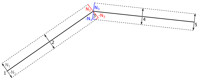
The figure shows that at point 3 2 pairs of normals coexist. The normals, marked in the figure in one color, are parallel to each other and in different directions, and if one of them is known, the second is calculated by inverting the vector.
In order to contain 2 multidirectional non-parallel normals at a point, the point must be duplicated, which occurs naturally during the formation of polygons. It can also be seen that in the place of fracture the formed polygons will overlap on the one hand, and on the other hand, on the contrary, form a gap. At first glance it seems that overlapping polygons do not pose a problem. That is, as long as the route line is completely opaque. In the case of a semitransparent line, the intersection of polygons will be darker, therefore, we must get rid of them. The gap is much easier to overcome; a polygonal insert is formed in its place.
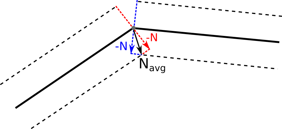
To eliminate overlapping polygons, we modify the normals so that the formed polygons do not overlap. To do this, calculate the average for two adjacent normals and shift both points along the new vector.
With this approach, one subtlety appears. Normals are no longer normalized, since we may need to significantly displace vertices at acute angles. As already mentioned, we eliminate the gaps in the route line using polygonal inserts. We support 3 ways to form these inserts.
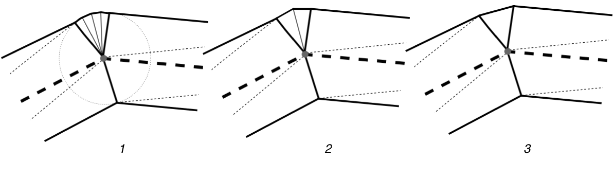
In the first case, the polygonal insertion is formed by the triangulation of a part of the circle inscribed in the junction of the route line segments. In the second case, an acute angle is formed; in the third, exactly one triangle is inserted. The geometry generation algorithm estimates the size of the discontinuity, the degree of divergence of the normals, and selects one of the methods for forming the polygonal insert. Among other things, at the ends of the route line are added rounding. They are formed in the same way as inserts of the 1st type. As a result, we got the inseparable geometry of the route line, which we can draw with any color, including semi-transparent.
Display of the covered part of the route
To cut off the traversed part of the route, the most obvious solution is to regenerate the geometry as the route passes. Obviously, this method will be costly in terms of performance, and the point here is not so much the complexity of the geometry generation algorithm as the cost of sending new vertex and index buffers to the GPU. In order not to regenerate the geometry for each update of the GPS-coordinates, we came up with the following approach. At each vertex of the generated geometry, we add a value equal to the length from the beginning of the route line to the projection of this vertex onto the route line.

Due to the interpolation of the values between the vertices for each fragment, we will have a value equal to the distance from the beginning of the route line to this fragment along the route line (DISTANCE_FROM_START). And with the help of the following simple pseudocode shader part of the route line will be cut off.
vec4 mainFragment() { vec4 color = ROUTE_LINE_COLOR; if (DISTANCE_FROM_START < CURRENT_CLIP_DISTANCE) color.a = 0.0; return color; } Here ROUTE_LINE_COLOR is the color of the route line, CURRENT_CLIP_DISTANCE is the current distance traveled along the route. In this approach, there is one small drawback: all the vertices of the polygonal insert will give a projection into one point.
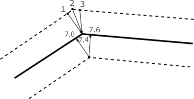
In the above example, points 1, 2 and 3 that are included in a polygon of type 2 are projected onto the central axis of the route line with a value of 7.4. In practice, this will be expressed in the formation of an uneven cut of the line at the border of two segments. But, in fact, for us, this behavior is not a problem, since the slice (flat or uneven) will in the overwhelming majority of cases be under the icon indicating the user's position.
Maneuvering
Maneuvers, as I have already said, are now limited to arrows with the designation of a turn. The main problem here is that at different levels of scale several arrows must merge into one in order not to be too small and unreadable.
It is clear that this time we wanted to do without the geometry regeneration for each frame. We implemented the following algorithm:
- Staging stage. At this stage, the main CPU is loaded. The line that comes from the system of building a route is divided into segments. Initially, we operated on one indivisible line, but in the process we encountered one serious problem when building a long route. Unfortunately, at length interpolation at large distances, we rested against the accuracy of float numbers. In the application, we use the Mercator coordinates, which causes a sufficiently large number of significant decimal places, and in shaders in OpenGL ES, the accuracy of float numbers is inferior to the accuracy of float numbers in the code for CPU (2-16 at highp against 2-24). As a result, in the course of real arithmetic in shaders, we lost accuracy, which led to the appearance of graphic artifacts. All our attempts to achieve the required accuracy, firstly, greatly complicated the fragmentary shader, and, secondly, there was always such a length of the route line, at which it did not work. Therefore, we decided to split the route line into such segments so that their length does not exceed a certain distance in the Mercator coordinate system. Now the values were interpolated independently for each segment, which saved us from problems with accuracy. To avoid breaks at the junction of the segments, the incision site was chosen in a special way. The broken line segment was cut closest to the desired place, and at the same time long enough so that the maneuver arrow could not reach the cut point. As a result of this stage, we obtain a set of vertex and index buffers with a triangulated route line geometry.
- The stage of updating the geometric data. The code related to this stage is executed for each frame immediately before rendering. The first task of this stage is to find out which segments of the route line are visible on the screen. Then, for each visible segment, the maneuvers are projected onto it. The fact is that for drawing arrows we use the same geometry as for drawing the route line itself, and it is necessary to pass an array of coordinates of the beginning and end of arrows to the shader. To calculate this array, we perform the following actions:
- We project the arrows onto the segment of the route line as it is (the original array comes from the route construction system).
- We merge the intersecting arrows into one (the arrows have certain restrictions on their length, both in the Mercator coordinates and in pixels, and therefore they can intersect).
- Shift the head of the arrow so that it lies completely on the flat part of the route (this is necessary to avoid distortion when sampling from the texture).
As a result of this stage, we determine what kind of geometry we should draw in the current frame, and also calculate an array with the coordinates of the beginning and end of the maneuver arrows. - Stage rendering. Here, of course, we load the GPU. We use the route line geometry for rendering (we determined the necessary vertex and index buffers at the previous stage). In the fragment shader, we pass an array of borders and a texture with the image of an arrow. Each element of the boundary array contains a one-dimensional coordinate of the beginning and end of the arrow, where the coordinate is the distance from the beginning of the current route line segment. According to these coordinates, in the fragment shader, texture coordinates are calculated for such a texture overlay on the geometry of the route line so that the arrows formed are in the specified areas. So that the arrow could protrude beyond the route line, a special line width is set (remember, we set it as a uniform variable). In addition, the texture of the arrow is divided into 3 parts: tail, head and center. The central part can stretch along the route without distortion, the tail and the head always retain their proportions. Pseudocode fragment shader for drawing arrows below.
struct Arrow { float start; float end; }; Arrow arrows[MAX_ARROWS_COUNT]; sampler2D arrowTexture; vec4 mainFragment(float distanceFromStart, float v) { for (int i = 0; i < MAX_ARROWS_COUNT; i++) { if (distanceFromStart <= arrows[i].start && distanceFromStart < arrows[i].end) { float u = (distanceFromStart - arrows[i].start) / (arrows[i].end - arrows[i].start); return texture(arrowTexture, vec2(u, v)); } } return vec4(0, 0, 0, 0); }
Conclusion
Today we reviewed the process of rendering navigation data in MAPS.ME. Our solutions do not pretend to be universal, however, I hope that you have found here something useful for yourself and your projects. Much more can be said about rendering in MAPS.ME, but we would like to understand what is interesting for our readers. Write in the comments about what you would be interested to read and, perhaps, the next post will be on the topic proposed by you.
Source: https://habr.com/ru/post/266693/
All Articles