We develop a monitoring system for 55,000 RTP video streams
Good day!
Recently I read a very interesting article about processing 50 gigabits / s on the server and remembered that I have an article in drafts about how we developed a system for monitoring video streams with a total traffic volume up to 100 Gbit / s a year ago. Once again, “read” it and decided to submit to the developers. The article is more devoted to the analysis of protocols and the search for an architectural solution, rather than tuning of various linux subsystems, because we have taken the path of load distribution between the server and network probes that are connected to 10 Gigabit Ethernet traffic flows.
')
If you are interested in how we could measure the characteristics of network streams from 55 thousand video cameras, I ask for cat.
In this article I plan to tell about:
What are we monitoring?
You need to monitor several 10G Ethernet transport links, which are transmitted by tens of thousands of video streams. The first installation - 22 thousand cameras, the second - 55 thousand. The average bit rate of the camera is 1 megabit / s. There are cameras with 2 megabits / s and 500 kilobits / s.
The video is transmitted using the RTP-over-UDP and RTP-over-RTSP-over-TCP protocols, and the connection is established via RTSP. At the same time, there can be one stream from one IP address (one address — one camera) or several (one address — one encoder, that is, from 1 to 16 streams).
Connection to ethernet links is possible only in the monitoring mode, using optical taps, in other words - in the non-intrusive mode. Such a connection is preferable, since in this case the traffic does not pass through the equipment and, therefore, it can in no way affect the quality of the services provided (the drop in the optical signal level on the splitter is considered quite insignificant). For operators, this is an extremely important argument. And for developers, an important nuance follows from such a connection - you will always have to watch the flows “from the side”, since packets cannot be transmitted to the network (for example, you cannot send a ping and get a response). It means that we will have to work in conditions of lack of information.
What are we measuring?
The stream quality assessment is based on the analysis of the RTP transport headers and the h.264 NAL-unit headers. Image quality is not measured. Instead, the transport stream of video frames is analyzed by the following criteria:
RTP can “go” both over UDP, and (mostly, in 90% of cases) over RTSP / TCP in the “Interleaving data” mode. Yes, despite the fact that the RFC for RTSP says that it is better not to use the Interleaving Data mode - see 10.12, rfc2326 ).
Total: the monitoring system is a complex that is connected in a non-intrusive mode to the nth number of 10-gigabit Ethernet links, which continuously “watches” the transfer of all RTP video streams present in the traffic and takes measurements with a certain time interval in order to save them to the base. According to data from the database, reports are regularly generated for all cameras.
And what's so complicated?
In the process of finding a solution, several problems were immediately fixed:
We are looking for a suitable solution ...
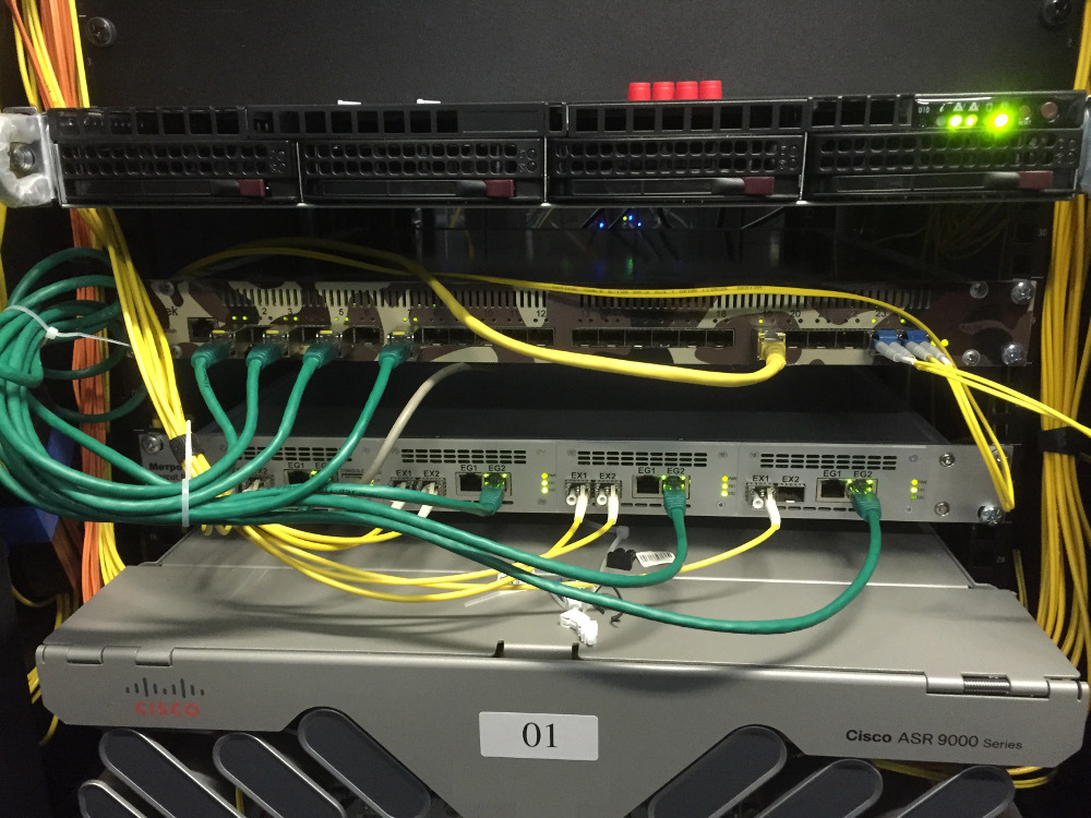
We, naturally, sought to make the most of our own experience. By the time we made the decision, we already had the implementation of processing ethernet packets on an FPGA-powered Bercut-MX device (easier, MX). With the help of Bercut-MX we were able to get the necessary fields for analysis from the Ethernet packet headers. We didn’t have the experience of handling such traffic volume by means of “ordinary” servers, so we were wary of this decision with some caution ...
It would seem that it remained to simply apply the method to the RTP packets and the golden key would be in our pocket, but MX can only handle traffic, it does not include the possibility of accounting and storing statistics. There are not enough memory for storing the found connections (IP-IP-port-port combinations) in the FPGA, because there can be about 15 thousand video streams in the 2x10-gigabit link that comes in for each input , the number of lost packets, and so on ... Moreover, searching at this speed and for that amount of data under the condition of lossless processing becomes a non-trivial task.
To find a solution, we had to “dig a little deeper” and figure out what algorithms we would use to measure quality and identify video streams.
What can be measured by the fields of the RTP packet?
The format of the RTP packet is described in rfc3550 .
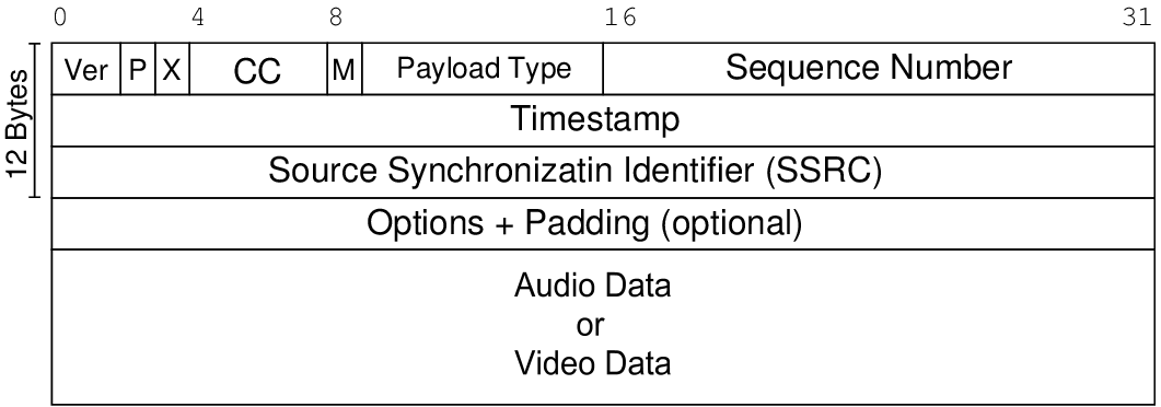
From the description it is clear that in terms of quality measurements in the RTP package, we are interested in the following fields:
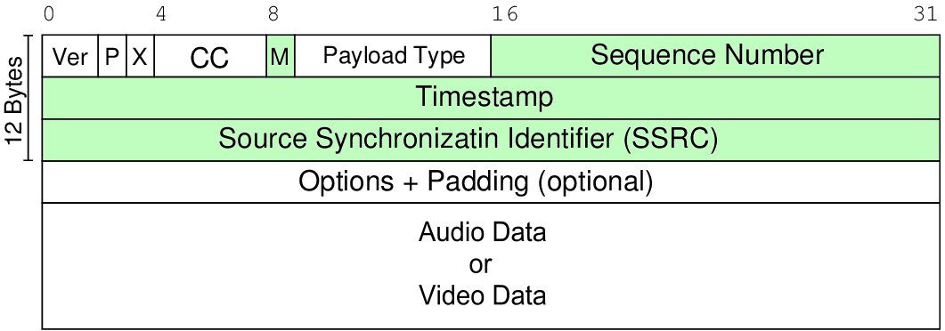
Obviously, the sequence number allows you to define the following stream parameters:
Timestamp allows you to measure:
Well, M-bit allows you to measure the frame rate. True, SPS / PPS frames of the h.264 protocol introduce an error, since video frames are not. But it can be leveled by using the information from the NAL-unit header, which always follows the RTP header.
Detailed algorithms for measuring parameters are beyond the scope of the article, I will not go deeper. If interested, then rfc3550 has an example of loss calculation code and formulas for calculating jitter . The main conclusion is that for measuring the basic characteristics of the transport stream, only a few fields from the RTP packets and NAL units are sufficient. And the rest of the information is not involved in the measurements and it can and should be discarded!
How to identify RTP streams?
To keep statistics, information obtained from the RTP header must be “tied” to some camera identifier (video stream). The camera can be uniquely identified by the following parameters:
Interestingly, we first made camera identification only by IP source and SSRC, relying on the fact that the SSRC should be random, but in practice it turned out that many cameras set the SSRC to a fixed value (say, 256). Apparently, this is due to resource savings. As a result, we had to add more ports to the camera ID. This solved the problem of uniqueness completely.
How to separate RTP packets from the rest of the traffic?
The question remains: how does the Bercut-MX, having accepted the packet, understand that this is an RTP? The RTP header does not have such an explicit identification as IP, it does not have a checksum, it can be transmitted via UDP with port numbers that are dynamically selected when a connection is established. And in our case, most of the connections have been established for a long time and you can wait a long time for reinstallation.
To solve this problem in rfc3550 (Appendix A.1) it is recommended to check the bits of the RTP version - these are two bits, and the Payload Type (PT) field is seven bits, which in the case of the dynamic type accepts a small range. We found out in practice that for the multitude of cameras we work with, PT fits in the range from 96 to 100.
There is one more factor - the port's parity, but as practice has shown, it is not always respected, so it had to be abandoned.
Thus, the behavior of the Bercut-MX is as follows:
It is obvious that with this approach there are false positives, since Under such simple criteria not only RTP packets can fall. But for us it is important that we definitely will not miss the RTP packet, and the “wrong” packets will be filtered out by the server.
To filter out false cases, the server uses a mechanism that registers the source of video traffic over several consecutively received packets (in the packet, there is a sequence number!). If several packets come with consecutive numbers, then this is not a coincidence and we start working with this stream. This algorithm turned out to be very reliable.
Moving on ...
Realizing that all the information going in the packets is not needed for measuring the quality and identifying flows, we decided to take all the highload & time-critical work on receiving and isolating the RTP packet fields on Bercut-MX, I mean FPGA. It “finds” the video stream, parses the packet, leaves only the required fields and sends it to a regular server in the UDP tunnel. The server measures each camera and saves the results to a database.
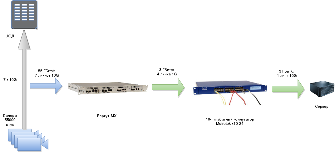
As a result, the server does not work with 50-60 Gigabit / s, but with a maximum of 5% (this is exactly the proportion of the data sent to the average packet size). That is, at the input of the entire system 55 Gigabit / s, and the server gets only 3 Gigabits per second!
As a result, we got this architecture:
And we received the first result in this configuration two weeks after the initial TZ was set!
What is the result of the server busy?
So, what does the server do in our architecture? His tasks:
Given that the total traffic at the server's input is about 3 Gigabit / s, the server copes even if we do not use any DPDK, but work simply via a linux socket (after increasing the buffer size for the socket, of course). Moreover, it will be possible to connect new links and MXs, because the performance margin remains.
Here is the top of the server (this is the top of only one lxc container, reports are generated in another):
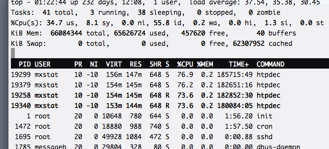
It shows that the entire load on the calculation of quality parameters and statistics is distributed over four processes evenly. We managed to achieve such a distribution due to the use of hashing in the FPGA: the IP hash is considered a hash function, and the low bits of the received hash determine the UDP port number that the statistics will go to. Accordingly, each process listening to its port receives approximately the same amount of traffic.
Cons and pros
It is time to boast and admit the shortcomings of the solution.
I'll start with the pros:
For the sake of justice, I will consider the disadvantages:
In the end, we have a software and hardware complex in which we can control both the part that parses the packets on the interfaces and the one that keeps the statistics. Full control over all nodes of the system literally saved us when the cameras began to translate to RTSP / TCP interleaved mode. Because in this case, the RTP header is no longer located in the packet at a fixed offset: it can be anywhere, even on the border of two packets (the first half in one, the second in the other). Accordingly, the algorithm for obtaining the RTP header and its fields has undergone dramatic changes. We had to do TCP reassembling on the server for all 50,000 connections - hence the rather high load on top.
We have never worked before in the field of high-loaded applications, but we managed to solve the problem at the expense of our skills in FPGA and it turned out pretty good. There is even a reserve - for example, another 20-30 thousand streams can be connected to a system with 55000 cameras.
Tuning linux subsystems (queuing by interrupts, increasing receive buffers, directive allocation of cores to specific processes, etc.) I left behind the article, since This topic is already very well covered.
I described not everything, the rake was collected a lot, so do not hesitate to ask questions :)
Many thanks to all who read to the end!
Links
Recently I read a very interesting article about processing 50 gigabits / s on the server and remembered that I have an article in drafts about how we developed a system for monitoring video streams with a total traffic volume up to 100 Gbit / s a year ago. Once again, “read” it and decided to submit to the developers. The article is more devoted to the analysis of protocols and the search for an architectural solution, rather than tuning of various linux subsystems, because we have taken the path of load distribution between the server and network probes that are connected to 10 Gigabit Ethernet traffic flows.
')
If you are interested in how we could measure the characteristics of network streams from 55 thousand video cameras, I ask for cat.
In this article I plan to tell about:
- what is monitored, how to connect to it;
- parameters of video streams to be measured;
- nuances ... understandably: there are nuances in every task;
- flour choice of suitable architecture;
- RTP protocol and its properties that allow the receiver to analyze the quality of the stream;
- identification of RTP packets in the trunk traffic;
- final system architecture;
- advantages and disadvantages of the chosen solution.
What are we monitoring?
You need to monitor several 10G Ethernet transport links, which are transmitted by tens of thousands of video streams. The first installation - 22 thousand cameras, the second - 55 thousand. The average bit rate of the camera is 1 megabit / s. There are cameras with 2 megabits / s and 500 kilobits / s.
The video is transmitted using the RTP-over-UDP and RTP-over-RTSP-over-TCP protocols, and the connection is established via RTSP. At the same time, there can be one stream from one IP address (one address — one camera) or several (one address — one encoder, that is, from 1 to 16 streams).
Connection to ethernet links is possible only in the monitoring mode, using optical taps, in other words - in the non-intrusive mode. Such a connection is preferable, since in this case the traffic does not pass through the equipment and, therefore, it can in no way affect the quality of the services provided (the drop in the optical signal level on the splitter is considered quite insignificant). For operators, this is an extremely important argument. And for developers, an important nuance follows from such a connection - you will always have to watch the flows “from the side”, since packets cannot be transmitted to the network (for example, you cannot send a ping and get a response). It means that we will have to work in conditions of lack of information.
What are we measuring?
The stream quality assessment is based on the analysis of the RTP transport headers and the h.264 NAL-unit headers. Image quality is not measured. Instead, the transport stream of video frames is analyzed by the following criteria:
- packets are not lost;
- Packages do not change their order;
- the number of frames corresponds to the SLA;
- bit rate corresponds to SLA;
- packet jitter is normal;
- and, finally, that the camera generally transmits packets.
RTP can “go” both over UDP, and (mostly, in 90% of cases) over RTSP / TCP in the “Interleaving data” mode. Yes, despite the fact that the RFC for RTSP says that it is better not to use the Interleaving Data mode - see 10.12, rfc2326 ).
Total: the monitoring system is a complex that is connected in a non-intrusive mode to the nth number of 10-gigabit Ethernet links, which continuously “watches” the transfer of all RTP video streams present in the traffic and takes measurements with a certain time interval in order to save them to the base. According to data from the database, reports are regularly generated for all cameras.
And what's so complicated?
In the process of finding a solution, several problems were immediately fixed:
- Non-intrusive connection. The monitoring system connects to the already working channels, in which most of the connections (via RTSP) are already established, the server and the client already know which ports are exchanged, but this is not known to us in advance. The well-known port is only for the RTSP protocol, but UDP streams can go through arbitrary ports (besides, it turned out that they often violate the SHOULD requirement for port parity / oddity, see rfc3550 ). How to determine that a particular package from some IP-address belongs to the video stream? For example, the BitTorrent protocol behaves similarly - at the stage of establishing a connection, the client and the server agree on the ports, and then all the UDP traffic looks like “just a bitstream”.
- In the connected links can be not only video streams. There may be HTTP, BitTorrent, SSH, and any other protocols that we use today. Consequently, the system must correctly identify video streams in order to separate them from the rest of the traffic. How to do this in real time with 8 ten-gigabit links? Of course, they are usually not filled up to 100%, so the total traffic will not be 80 Gbps, but about 50-60, but this is not so little.
- Scalable. Where there are already a lot of video streams, there can be even more of them, since video surveillance has long since justified itself as an effective tool. This suggests that there should be a performance margin and reserve for links.
We are looking for a suitable solution ...
We, naturally, sought to make the most of our own experience. By the time we made the decision, we already had the implementation of processing ethernet packets on an FPGA-powered Bercut-MX device (easier, MX). With the help of Bercut-MX we were able to get the necessary fields for analysis from the Ethernet packet headers. We didn’t have the experience of handling such traffic volume by means of “ordinary” servers, so we were wary of this decision with some caution ...
It would seem that it remained to simply apply the method to the RTP packets and the golden key would be in our pocket, but MX can only handle traffic, it does not include the possibility of accounting and storing statistics. There are not enough memory for storing the found connections (IP-IP-port-port combinations) in the FPGA, because there can be about 15 thousand video streams in the 2x10-gigabit link that comes in for each input , the number of lost packets, and so on ... Moreover, searching at this speed and for that amount of data under the condition of lossless processing becomes a non-trivial task.
To find a solution, we had to “dig a little deeper” and figure out what algorithms we would use to measure quality and identify video streams.
What can be measured by the fields of the RTP packet?
The format of the RTP packet is described in rfc3550 .
From the description it is clear that in terms of quality measurements in the RTP package, we are interested in the following fields:
- sequence number - 16-bit counter, increasing with each packet sent;
- timestamp - timestamp, for h.264, the sampling rate is 1/90000 s (i.e., corresponding to a frequency of 90 KHz);
- Marker-bit. In rfc3550, it is generally described that this bit is intended to denote “significant” events , and in fact this bit most often cameras mark the beginning of a video frame and specialized packages with SPS / PPS information.
Obviously, the sequence number allows you to define the following stream parameters:
- packet loss (frame loss);
- repeated packet sending (duplicate);
- changing the order of arrival (reordering);
- rebooting the camera, with a large "gap" in the sequence.
Timestamp allows you to measure:
- delay variation (also called jitter). At the same time, a 90 kHz counter should be operated on the receiving side;
- in principle, the delay in passing the packet. But for this you need to synchronize the camera time with the timestamp, and this is possible if the camera transmits sender reports (RTCP SR), which is generally wrong, because in real life, many cameras ignore the RTCP SR package (about half of the cameras we've worked with).
Well, M-bit allows you to measure the frame rate. True, SPS / PPS frames of the h.264 protocol introduce an error, since video frames are not. But it can be leveled by using the information from the NAL-unit header, which always follows the RTP header.
Detailed algorithms for measuring parameters are beyond the scope of the article, I will not go deeper. If interested, then rfc3550 has an example of loss calculation code and formulas for calculating jitter . The main conclusion is that for measuring the basic characteristics of the transport stream, only a few fields from the RTP packets and NAL units are sufficient. And the rest of the information is not involved in the measurements and it can and should be discarded!
How to identify RTP streams?
To keep statistics, information obtained from the RTP header must be “tied” to some camera identifier (video stream). The camera can be uniquely identified by the following parameters:
- Source and destination IP addresses
- Source and destination ports
- SSRC. It is of particular importance when several streams are broadcast from the same IP, i.e. in the case of multiport encoder.
Interestingly, we first made camera identification only by IP source and SSRC, relying on the fact that the SSRC should be random, but in practice it turned out that many cameras set the SSRC to a fixed value (say, 256). Apparently, this is due to resource savings. As a result, we had to add more ports to the camera ID. This solved the problem of uniqueness completely.
How to separate RTP packets from the rest of the traffic?
The question remains: how does the Bercut-MX, having accepted the packet, understand that this is an RTP? The RTP header does not have such an explicit identification as IP, it does not have a checksum, it can be transmitted via UDP with port numbers that are dynamically selected when a connection is established. And in our case, most of the connections have been established for a long time and you can wait a long time for reinstallation.
To solve this problem in rfc3550 (Appendix A.1) it is recommended to check the bits of the RTP version - these are two bits, and the Payload Type (PT) field is seven bits, which in the case of the dynamic type accepts a small range. We found out in practice that for the multitude of cameras we work with, PT fits in the range from 96 to 100.
There is one more factor - the port's parity, but as practice has shown, it is not always respected, so it had to be abandoned.
Thus, the behavior of the Bercut-MX is as follows:
- we receive a package, we sort into fields;
- if the version is 2 and the payload type is within the specified limits, then send the headers to the server.
It is obvious that with this approach there are false positives, since Under such simple criteria not only RTP packets can fall. But for us it is important that we definitely will not miss the RTP packet, and the “wrong” packets will be filtered out by the server.
To filter out false cases, the server uses a mechanism that registers the source of video traffic over several consecutively received packets (in the packet, there is a sequence number!). If several packets come with consecutive numbers, then this is not a coincidence and we start working with this stream. This algorithm turned out to be very reliable.
Moving on ...
Realizing that all the information going in the packets is not needed for measuring the quality and identifying flows, we decided to take all the highload & time-critical work on receiving and isolating the RTP packet fields on Bercut-MX, I mean FPGA. It “finds” the video stream, parses the packet, leaves only the required fields and sends it to a regular server in the UDP tunnel. The server measures each camera and saves the results to a database.
As a result, the server does not work with 50-60 Gigabit / s, but with a maximum of 5% (this is exactly the proportion of the data sent to the average packet size). That is, at the input of the entire system 55 Gigabit / s, and the server gets only 3 Gigabits per second!
As a result, we got this architecture:
And we received the first result in this configuration two weeks after the initial TZ was set!
What is the result of the server busy?
So, what does the server do in our architecture? His tasks:
- listen to a UDP socket and read fields with packed headers;
- parse incoming packets and retrieve the RTP header fields along with the camera IDs;
- to correlate the received fields with those that were received before, and to understand whether the packets were lost, whether the packets were sent again, the order of arrival changed, what was the variation in packet delay (jitter), etc .;
- fix measured in the base with reference to time;
- analyze the database and generate reports, send traps on critical events (high packet loss, loss of packets from some camera, etc.).
Given that the total traffic at the server's input is about 3 Gigabit / s, the server copes even if we do not use any DPDK, but work simply via a linux socket (after increasing the buffer size for the socket, of course). Moreover, it will be possible to connect new links and MXs, because the performance margin remains.
Here is the top of the server (this is the top of only one lxc container, reports are generated in another):
It shows that the entire load on the calculation of quality parameters and statistics is distributed over four processes evenly. We managed to achieve such a distribution due to the use of hashing in the FPGA: the IP hash is considered a hash function, and the low bits of the received hash determine the UDP port number that the statistics will go to. Accordingly, each process listening to its port receives approximately the same amount of traffic.
Cons and pros
It is time to boast and admit the shortcomings of the solution.
I'll start with the pros:
- no loss at the junction with 10G-links. Since the FPGA takes the whole “hit”, we can be sure that every packet will be analyzed;
- monitoring 55,000 cameras (and more) requires only one server with one 10G card. We are currently using a 2x Xeon based server with 4 cores of 2400 MHz each. Enough with a margin: in parallel with the collection of information reports are generated;
- monitoring of 8 “dozen” (10G links) fits into only 2-3 units: there is not always a lot of space and power in a rack for a monitoring system;
- when connecting links from MXs through the switch, you can add new links without stopping monitoring, since no fee to insert the server is not necessary and for this you do not need to turn it off;
- the server is not overloaded with data, it receives only what is needed;
- headers from MX come in a jumbo Ethernet package, which means the processor will not get choked up by interrupts (besides, we do not forget about interrupt coalescing).
For the sake of justice, I will consider the disadvantages:
- because of the rigid optimization for a specific task, the addition of support for new fields or protocols requires changes in the FPGA code. This leads to more time consuming than if we did the same on the processor. Both in development and testing, and at deploy;
- video information is not analyzed at all. The camera can shoot an icicle hanging in front of it, or be turned in the wrong direction. This fact will go unnoticed. We, of course, made it possible to record video from the selected camera, but not to go through the operator with all 55,000 cameras!
- server and FPGA-powered devices - this is more expensive than just one or two servers;)
Summary
In the end, we have a software and hardware complex in which we can control both the part that parses the packets on the interfaces and the one that keeps the statistics. Full control over all nodes of the system literally saved us when the cameras began to translate to RTSP / TCP interleaved mode. Because in this case, the RTP header is no longer located in the packet at a fixed offset: it can be anywhere, even on the border of two packets (the first half in one, the second in the other). Accordingly, the algorithm for obtaining the RTP header and its fields has undergone dramatic changes. We had to do TCP reassembling on the server for all 50,000 connections - hence the rather high load on top.
We have never worked before in the field of high-loaded applications, but we managed to solve the problem at the expense of our skills in FPGA and it turned out pretty good. There is even a reserve - for example, another 20-30 thousand streams can be connected to a system with 55000 cameras.
Tuning linux subsystems (queuing by interrupts, increasing receive buffers, directive allocation of cores to specific processes, etc.) I left behind the article, since This topic is already very well covered.
I described not everything, the rake was collected a lot, so do not hesitate to ask questions :)
Many thanks to all who read to the end!
Links
- booklet of the monitoring system Bercut-MX / RTP
- Probably the most promoted company engaged in similar tasks - bridgetech
- Network Accelerator Cards in PC for traffic processing - napatech . One of the techniques - Frame Classification - is similar to the approach we used. However, it will not cope with the heuristic search for the RTP header anywhere in the TCP packet.
- rfc3550 - RTP is described here
- rfc2326 - the RTSP is described here
- Mega-article about processing 50 gigabits on the server
Source: https://habr.com/ru/post/266561/
All Articles