As one of the operators increased the capacity of 3G in a densely populated district of Minsk, not forgetting about the coming on the heels of LTE
So it turned out that not far from my monastery began to establish a base station. As a person close to telecommunications, I could not disregard this event.
Under the cat, the time-consuming process of installing a singleRAN modular base station in the most densely populated area of the city “Kamennaya Gorka” is described, the contents of the operator boxes on the lighting poles are described and the purpose of the devices installed in them is told.
We will skip the office planning stage (it is worthy of a separate post, given our reality) and move to the scene. Since the area is very high building density, most of the buildings are high-rise and belong to the housing stock, radio relay lines (RRL) are almost never used, and transport to the stations is provided by fiber-optic communication lines (FOCL). Fortunately, optics for the home Internet have already been laid in the basements of neighboring buildings, so there are cable wells and lines in which you can lay the necessary communications, although I had to dig and drill a lot.
')
The fact is that a non-standard configuration was developed to accommodate the equipment, due to the need to cover a large neighborhood. Three sectors of the same station, located 130 meters apart, were set apart on three pillars.
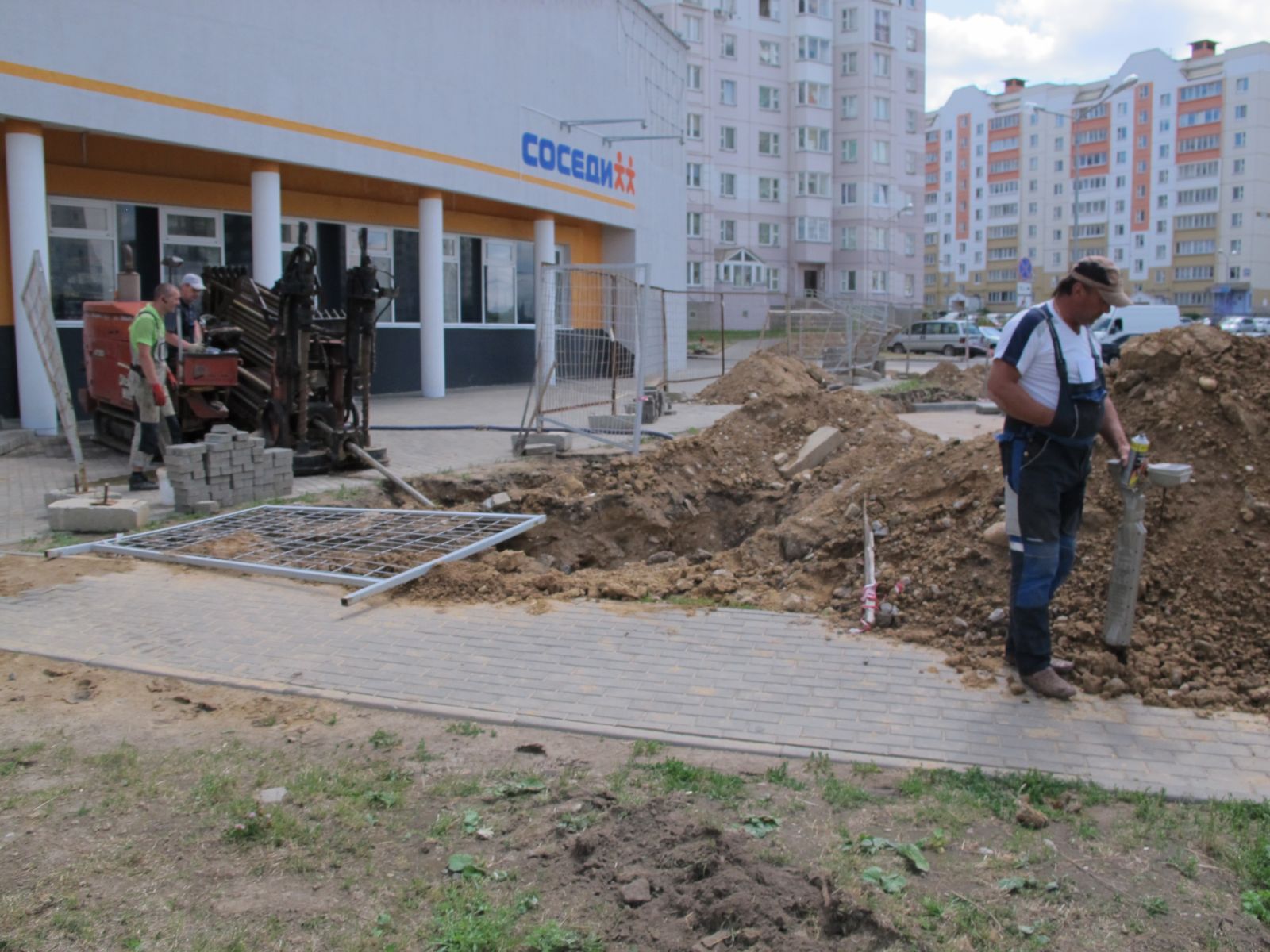
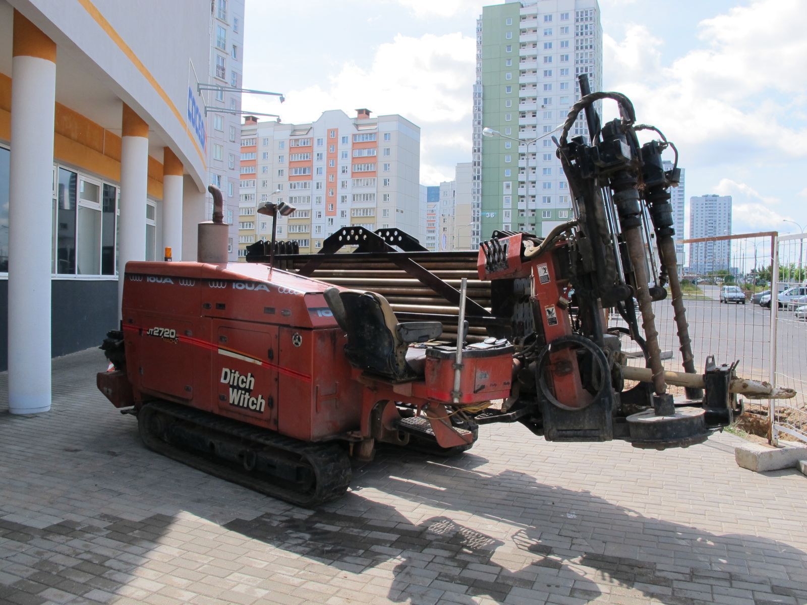
In order not to interfere with pedestrians and dig paths, two drills were involved.
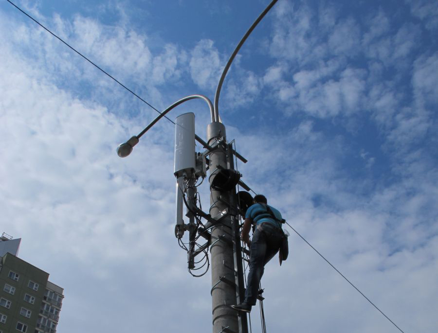
When the drilling team finishes the job, cable workers and installers are involved.

First, a harness is mounted on each of the three poles for hanging the antennas and on one of them an anti-vadal box to house the (e) NodeB itself. It is worth noting that the appearance of the support had to be affirmed in Minsk Region - such requirements are in Belarus. In general, with base stations in terms of monitoring compliance with various state standards strictly - before installing the station's power and frequency characteristics are authorized by the Telecommunications Control Inspectorate of BelGIE. And after installation, representatives of the network development group and inspectors leave to the site to make sure that all standards are observed and that the station complies with the design characteristics.

The photo shows the preparatory work for the installation of antennas RFS, one of the oldest manufacturers of equipment for telecommunication networks, in no way inferior and even surpassing Kathrein, Erricsson, Allgon and others in some points.

Antennas are designed to receive and transmit a signal in the range of 1710-2200MHz.

On all three pillars, this is the azimuth configuration - the antennas “shine” in the space between houses that are perpendicular to the road.

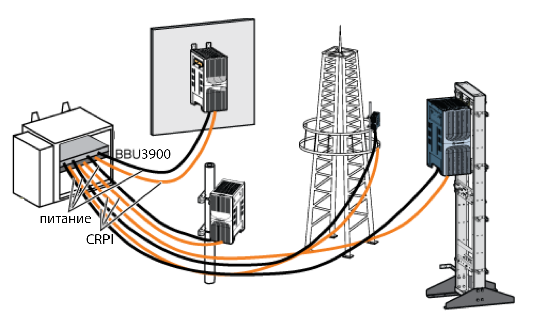
Schematically show the connection of antennas, radio modules RRU to the baseband processing unit BBU (baseband unit) can be so.

Naturally, the power cable is also suitable for the RRU - after all, it is an active hardware-software system that is just the basis of the SingleRAN (radio access network) philosophy - one radio module can support different standards of the mobile network.
Placing the radio modules directly at the antennas outside the telecommunication cabinet is a fairly new solution, due to the fact that the feeders are expensive and sensitive enough to mechanical damage, which creates additional difficulties during installation, maintenance and replacement in case of damage. It should also be remembered that the theft of these feeders and ground cables often occurs, because they contain copper, so beloved by the frequent guests of non-ferrous metal reception points.
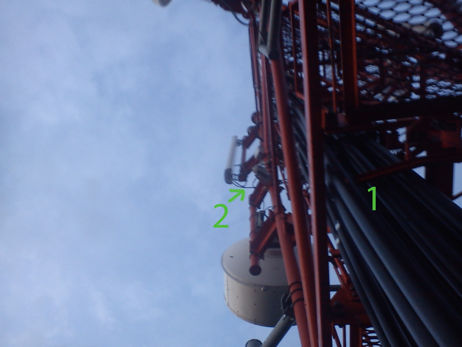
Here are such radio frequency feeders [1] used to connect to antennas, however, more antenna jump cables were also used for antennas [2].
A bit about feeders and jumpers
From Wikipedia:
The feeder (from the feed to the feed) is an electrical circuit (transmission line) and auxiliary devices by which the energy of the radio frequency signal is supplied from the radio transmitter to the antenna or from the antenna to the radio receiver.
There are open and closed feeders. Shielded lines (for example, coaxial cable) belong to closed feeders. To open - unshielded wire lines, dielectric waveguides, lens and specular quasi-optical lines.
Jumper in radio paths - cable, usually terminating feeders on the last few meters of the feeder. That he connects to the antenna.
The use of the jumper is due to the fact that the feeders themselves have a sufficiently large diameter (5/4 'or 7/8') and as a result there are difficulties in bending when connected to antennas, the jumper, in turn, has a diameter of 1/2 'or 3 /eight'.
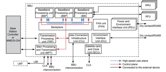
The scheme of interconnection of modules in this BS. A single chassis and many modules for a variety of needs - this is almost a world standard.
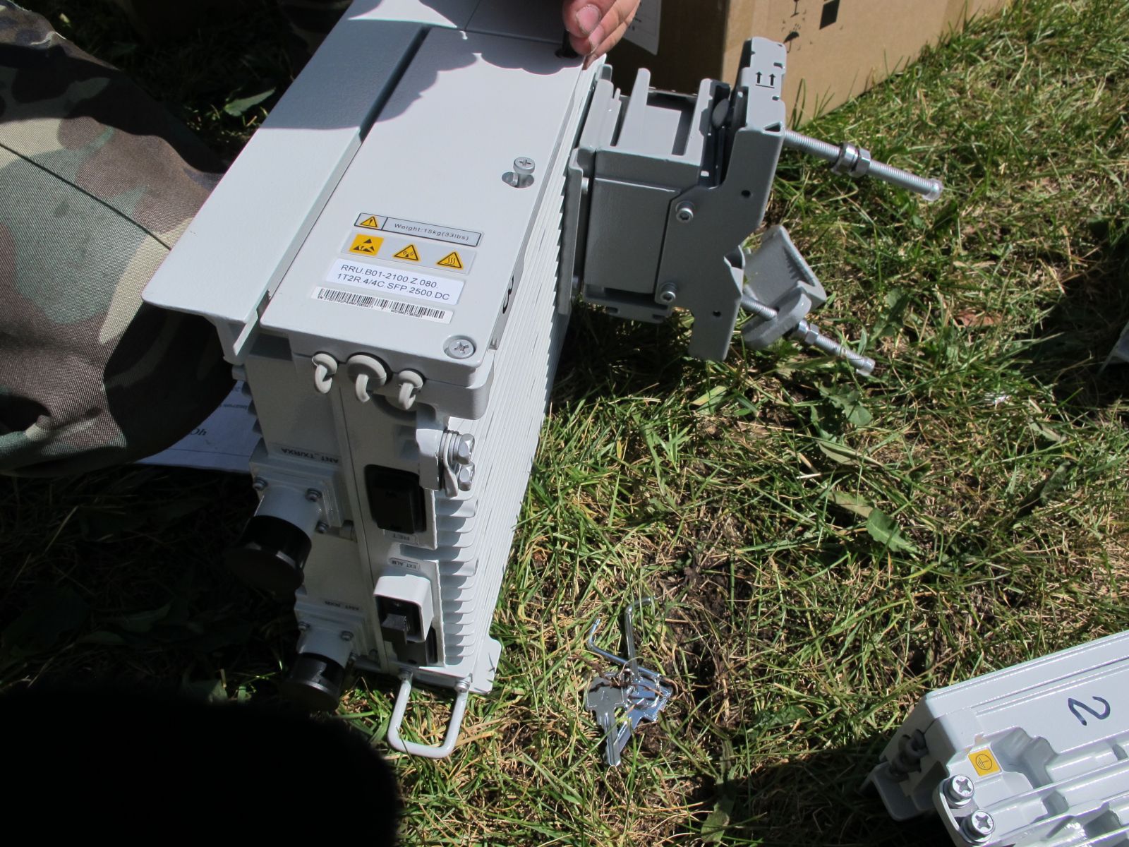
This is, in fact, the RRU module, which converts the signal from the BBU into an RF signal with subsequent amplification for radiation into the air, and also performs the reverse conversion of the signal received by antennas from subscriber devices.
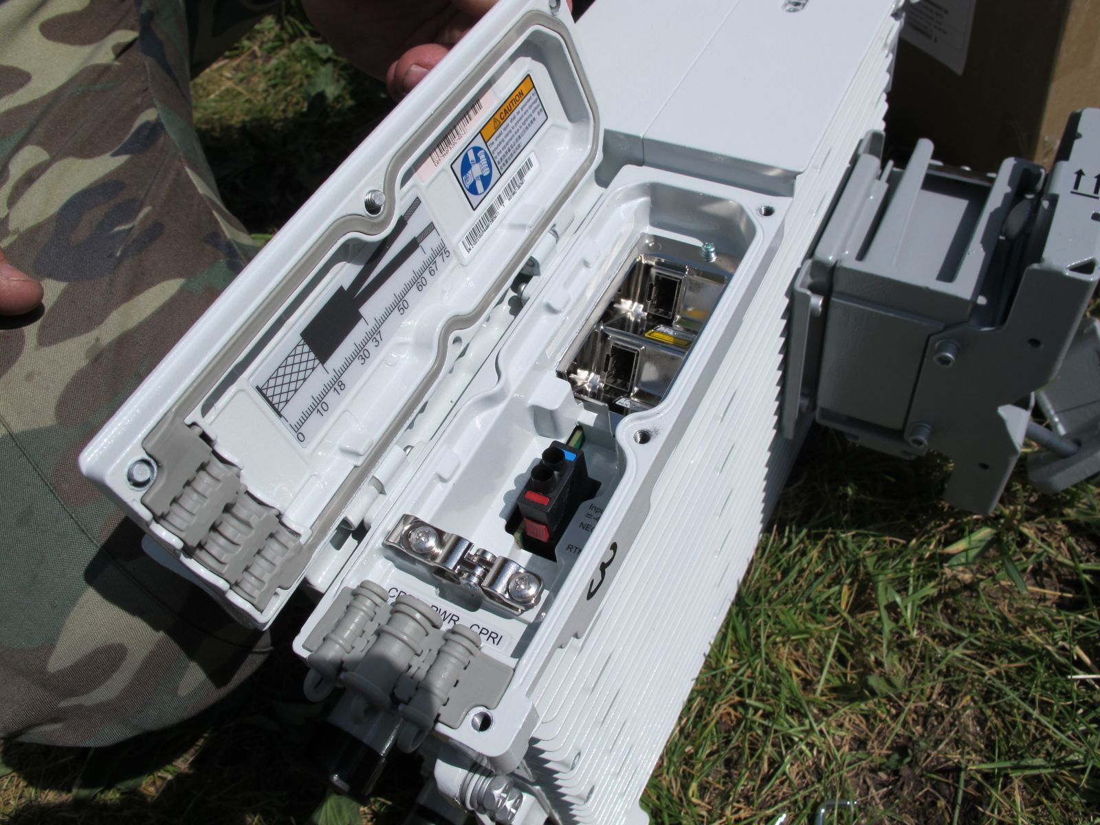
In the all-weather compartment, the RRU includes connectors for the power supply of 48 V DC and two optical CPRI (Common Public Radio Interface) cables through which digital data (both service and signal) is exchanged with the BBU. One cable is connected to the base-frequency processing module; the second connector in the radio module is used to cascade up to three RRUs. It is necessary for the very different task of cell division into sectors.
CPRI is a fairly new interface supported by all the giants of cellular equipment manufacturing. For example, this standard allows you to connect remotes up to 40 kilometers of radio modules.
Let's go higher.

Few people notice small antennas at base stations, to which only one radio interface is suitable. The arrow on the photo is a GPS receiver, it is needed to receive accurate time signals. In CDMA standards, using GPS to synchronize between BSs reduces the cost of frequency calibrations. Exact satellite time allows you to achieve a smoother handover on the network, and in LTE and LTE Advanced GPS is a vital component for processing TDD (time-division duplex), i.e. synchronous switching of the signal processing unit in the reception / transmission modes.

It looks like this, by the way, it is easy to confuse it with the lantern of the light barrier of a high-altitude object from the ground.

So, from top to bottom, the contents of a typical BS DBS3900: air cooling and ventilation system [1], power module [2], BBU [3], and at the very bottom - HAU [4] (heat assembly unit), in Russian “heater” . Always have to remember our winters.
DBS3900 is a good carrier solution that supports a smooth transition to LTE eNodeB networks according to the SingleRAN strategy - with simultaneous provision of GSM, UMTS, LTE services in various variations.
Now about each module in turn.
The power supply module is the largest in the rack and consists of several subracks:
PMU [1], AC / DC PSU [2] (rectifiers), EPU [3]. The PMU is a control unit for power supply, distribution of power supply and alarm system of external accidents (smoke sensor, opening sensing, temperature sensor, etc.). It communicates with the main module via RS 232 or RS 422 interface, controls charging-discharging of backup power batteries. PSU converts 220V AC to -48V DC, monitors the status and status of the batteries (battery). EPU - module connecting to an external power source and its wiring to all modules. It contains protective devices that protect equipment from power supply and battery failures.
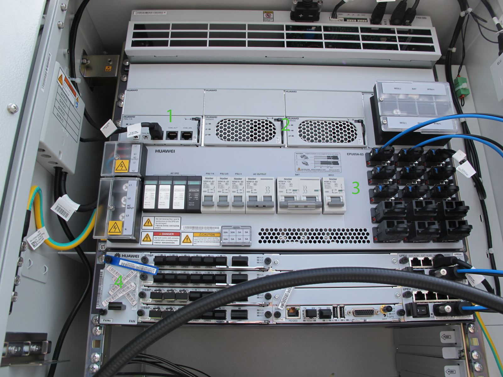
BBU [4] - connects BS with BSC or RNC (in case of use in 3G network). It performs the functions of managing the allocation of BS resources, such as frequencies, channels, bandwidth, as well as BS communication lines with the outside world, provides reference synchronization - accurate time. Specifically, this base station was installed with a multi-mode module UMPT (universal main processing and transmission unit) to support UMTS, and in the future, and LTE.

UMPT - universal main processing and transmission unit, the BBU main module - it stores all the necessary data for the station operation - it can be configured either remotely or via the console port, or USB. This unit processes the signaling in the GSM and UMTS networks, E-UTRAN in LTE, it also gets optics for exchanging traffic with the transport network (usually from 100 Mbit / s to 1 Gbit / s), right there is a port for GPS synchronization . To expand the BS capacity, there is an optical CI-port for communication with the second BBU. During operation, if necessary, the capacity of the data exchange channel with the BS can be increased by adding additional UTRP (universal transmission processing unit) transport modules, each of which can produce an additional 2 Gbps of exchange channel with the operator’s network.
WBBP - WCDMA baseband processing unit, communication module with radio modules RRU. As many have already guessed, to support the BBU standard UMTS. Each radio module provides a total exchange rate with subscribers - 512 Mbit outgoing and 768 Mbit downward and limited to 384 connections with user terminals. At the moment, this type of station can provide simultaneous communication with approximately 1500 devices.
For the final LTE input, it will be enough to install another LBBP board or a second BBU module with them, throw in the firmware - and everything will be ready!
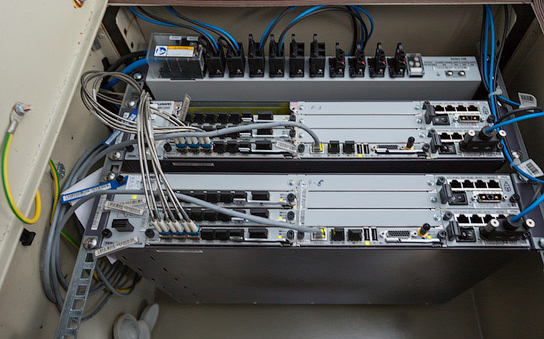
And this is how some of the similarly equipped BBUs at another facility look like - in the world-famous after the World Hockey Championship 2014 “Minsk-Arena”. Two baseband processing modules are used to simultaneously service a larger number of subscribers inside the arena.
Described in the post BS after full installation and commissioning.

The box on the left is a battery box, for back-up equipment with problems in the urban network.
With a long absence of electricity provided for charging batteries from a three-phase benzo-generator. Yes, in Belarus, you can just come and leave the buzzing generator on the street unattended, however, it did not do without cases when especially enterprising citizens quietly took this device (so necessary in their personal economy) in an unknown direction.

Neighboring sector, working in the triad with the equipment of the cabinet BTS3900 in the previous photo.
So with a concrete example, I tried to show how operators using modular iron kill two birds with one stone - they increase the capacity of the existing network and take care of the introduction of LTE, and hopefully, without losing the services of the previous generation.
Source: https://habr.com/ru/post/266541/
All Articles