“Sweet” programming, or How to select a label from a can of jam in Mathematica?

Translated from the Mathematica at StackExchange discussion of " How to peel the labels from marmalade jars using Mathematica? "
The code in this article can be downloaded here (~ 31 MB).
Many thanks to Kirill Guzenko KirillGuzenko for his help in translating and preparing the publication.
How can you select the contents of the label from the can specified below (the point where the frame was taken, the geometry of the can, its contents - all of this is unknown to us),
to get something like that — the same label as it was before it was on the bank?
')
The basic idea is this:
- Find the label.
- Find the borders of the label.
- We find the display of the image pixel coordinates on cylindrical coordinates.
- Transform the image using the found display.
The algorithm proposed by us works only for images in which:
- The label is brighter than the background (this is needed to detect the label).
- The label is rectangular (this is necessary in order to assess the quality of the display).
- The bank must be in a vertical position (this is necessary in order to preserve the simple form of the display function).
- The can must be cylindrical (this is necessary in order to preserve the simple form of the display function).
It should be noted that the algorithm is modular. That is, you can add your own label detection algorithm, which will not require a dark background, or you can write your own display quality evaluation function, which will allow you to work with oval or polygonal labels.
The resulting algorithm works completely automatically (however, there is an option to manually set the jars' boundaries), that is, it takes the original image, and then displays an image with a grid and a label.
Here is my “quick” solution. It is a bit like the azdahak user’s solution, but instead of cylindrical coordinates it uses approximate mapping. On the other hand, control parameters cannot be set manually - all display coefficients are automatically determined:
The label stands out clearly against a dark background, so I can easily find it using binarization:
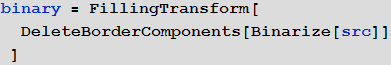
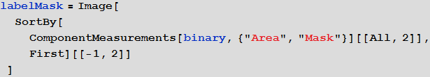
I just choose the largest item and I believe that this is the label:
In the next step, you need to select all the boundaries of this area using the convolution ( ImageConvolve ) of the resulting label mask:
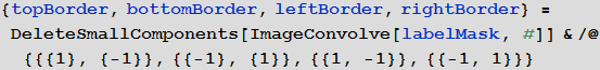
A small auxiliary function, shown below, allows you to find all white pixels in one of these four images and convert their indices to coordinates ( Position returns indices, and indices are pairs of numbers {y, x} , which, when y = 1, specify an image bandwidth 1 pixel at the top of the image. But all image processing functions take the coordinates in the form of pairs {x, y} , which, when y = 0, define an image strip with a thickness of 1 pixel from the bottom of the image. This leads to the need to convert the indices produced by Position into Essentially, about ychnye Cartesian coordinates for further use):
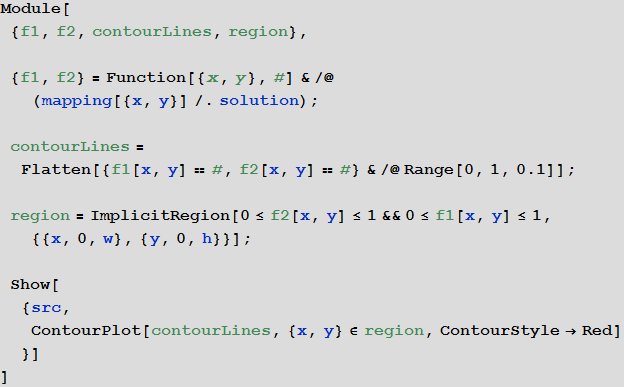
Now I have four separate lists of coordinates for the upper, lower, left, and right borders of the label. We now define the display of image coordinates into cylindrical coordinates:
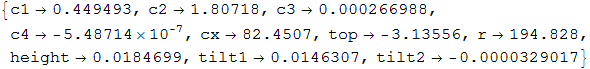
This mapping is obviously a rough approximation to cylindrical coordinates. However, it is very easy to find the optimal values of the coefficients c1, c2, ..., c8 using the NMinimize function:
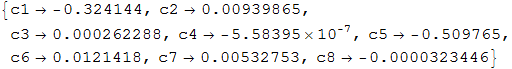
Thus, we find a function that produces the optimal display of our label on a rectangle - the points on the left border are displayed in {0, [something]} , and the points on the upper border are displayed in {[something], 1} and so on .
The display will look like this:
Now you can transfer this mapping directly to the ImageForwardTransformation function:
Artifacts in the image we got from the original image. A higher resolution version of the image would give a better result. Distortions in the left part occurred due to insufficient quality display function. This can be corrected by improving it, as will be discussed below.
Algorithm operation with larger images
I tried to apply the same algorithm to a higher resolution image and the result looks like this:
The result suggests that it is worth a little tweak the part responsible for detecting the label (first DeleteBorderComponents , and then FillingTransform ), and add additional conditions in the display formula taking into account the perspective (for low-resolution images, the changes will be almost invisible). You may notice that closer to the edges of the image, the constructed second-order display function works with some minor distortions.
Improved display function
After conducting a series of studies and experiments, we managed to find a mapping that eliminates cylindrical distortions (most of them, at least):
This is a cylindrical mapping that uses the Taylor series to approximate the arcsine, since the direct use of the arcsine function makes symbolic and numerical optimization quite difficult. The Clip function is used to prevent complex numbers from appearing in the optimization process. Using NMinimize to solve this non-linear optimization problem will not produce fast results as the function searches the global minimum of functionality using hybrid symbol-numerical methods, so it was decided instead to use the FindMinimium function, which perfectly looks using purely numerical methods minimum.
Here is what we get as a result of the mapping:
The resulting label image:
The obtained boundaries describe the contour of the label quite well. The characters look the same in size, and therefore the distortion has little effect. The optimization solution can also be checked directly: by optimizing, we will try to estimate the cylinder radius R and the X coordinate of the cylinder center, and the resulting values will be only a few pixels away from their actual positions in the image.
Checking the operation of the algorithm on real data
Similar pictures were found on Google and the developed algorithm was tested. The results of the algorithm in fully automatic mode are shown below, but some of the images have been cropped a bit beforehand. The results look very promising:
As expected, label detection is the least sustainable step of the algorithm, and therefore it was necessary to crop images in some cases. If you mark the points on the label and outside it, the segmentation based on the boundaries will have to give the best result.
Additional algorithm improvements
User Szabolcs offered an interactive version of the code that allows you to improve the result.
For my part, I propose to improve the proposed interactive interface by manually selecting the left and right edges of the image, for example, using locators:
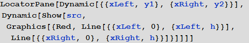
Then it will be possible to get the parameters r and cx in an explicit form, and not through optimization:
Using this solution, the result is practically without distortion:
Source: https://habr.com/ru/post/266517/
All Articles