Implementation of multi-threaded game engine architecture
With the advent of multi-core processors, it became necessary to create a game engine based on a parallel architecture. The use of all processors of the system - both graphic (GP) and central (CPU) - opens up much more possibilities compared to a single-threaded engine based on GP only. For example, using more CPU cores, you can improve the visual effects by increasing the number of physical objects used in the game, as well as achieve more realistic behavior of the characters through the implementation of advanced artificial intelligence (AI).
Consider the features of the implementation of a multi-threaded game engine architecture.
The multi-threaded architecture of the game engine allows you to use the capabilities of all processors of the platform to the maximum. It involves the parallel execution of various functional blocks on all available processors. However, to implement such a scheme, it turns out, is not so simple. Individual elements of the game engine often interact with each other, which can lead to errors when they are executed simultaneously. To handle such scenarios, the engine has special data synchronization mechanisms that exclude possible locks. It also implements methods for simultaneous synchronization of data, thereby minimizing the execution time.
To understand the presented materials, one needs to be well-versed in modern methods of creating computer games, multi-threading support for game engines, or to improve the performance of applications in general.
The parallel execution state is a key notion of multithreading. Only by dividing the game engine into separate systems, each working in its own mode and practically not interacting with the rest of the engine, one can achieve the highest efficiency of parallel computing and reduce the time required for synchronization. It is not possible to completely isolate separate parts of the engine, excluding all shared resources. However, for operations such as retrieving data on the position or orientation of objects, individual systems may use local copies of data, rather than shared resources. This allows you to minimize the dependence of data in different parts of the engine. Notifications of changes in general data made by a separate system are transmitted to the state manager, which places them in a queue. This is called messaging mode. This mode assumes that, after completing the execution of tasks, the engine systems receive notification of changes and update their internal data accordingly. Such a mechanism can significantly reduce synchronization time and the dependence of systems on each other.
')
In order for the execution state manager to work efficiently, it is recommended to synchronize operations on a certain clock pulse. This allows all systems to operate simultaneously. In this case, the clock frequency does not necessarily have to correspond to the frame rate. Yes, and the duration of the cycles may not depend on the frequency. It can be chosen in such a way that one clock corresponds to the time required to transmit one frame (regardless of its size). In other words, the frequency or duration of clocks is determined by the specific implementation of the state manager. Figure 1 shows the “free” step-by-step mode of operation, in which it is not required that all systems complete the operation in the same clock cycle. The mode in which all systems complete operations in one cycle is called “hard” step-by-step mode. It is schematically depicted in Figure 2.
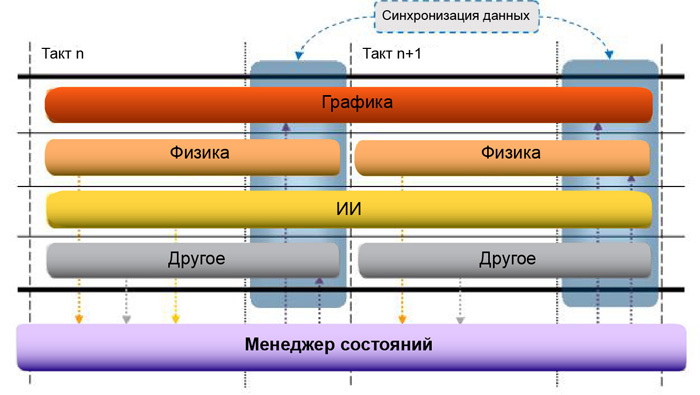
Figure 1. Run state in step free mode
In free step-by-step mode, all systems operate continuously for a predetermined period of time required to complete the next batch of calculations. However, the name “free” should not be taken literally: the systems are not synchronized at an arbitrary point in time, they are only “free” in the choice of the number of cycles required for the execution of the next stage.
As a rule, in this mode it is not enough to send a simple state change notification to the state manager. You must also transfer the updated data. This is because the system that changed the shared data may be in a running state, while another system that is waiting for this data is ready to perform the update. In this case, more memory is required, since you need to create more copies of the data. Therefore, the “free” regime cannot be considered a universal solution for all occasions.
In this mode, the execution of tasks of all systems is completed in one cycle. Such a mechanism is easier to implement and does not require the transfer of updated data along with the notification. Indeed, if necessary, one system can simply request new values from another system (of course, at the end of the execution cycle).
In hard mode, you can implement a pseudo-free step-by-step mode of operation, distributing the calculations between the various steps. In particular, this may be required for AI calculations, where the initial “common goal” is calculated for the first beat, which is gradually refined in the next stages.
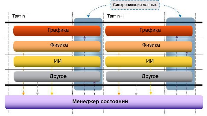
Figure 2. Execute status in hard walk mode
Changing shared data across multiple systems may result in a conflict of changes. In this case, in the messaging system it is necessary to provide an algorithm for selecting the correct total value. There are two main approaches based on the following criteria.
All obsolete data (according to any of the criteria) can be simply overwritten or excluded from the notification queue.
Since the final value may depend on the order of the changes, it can be very difficult to use the relative values of the total data. In such cases, absolute values should be used. Then, when updating local data, systems can simply replace old values with new ones. The optimal solution is to choose absolute or relative values depending on the specific situation. For example, general data, such as position and orientation, should have absolute values, since the order of change is important to them. Relative values can be used, for example, for a particle generation system, since all information about particles is stored only in itself.
When developing the engine, the focus is on the flexibility needed to further expand its functionality. This will optimize it for use under certain restrictions (for example, by memory).
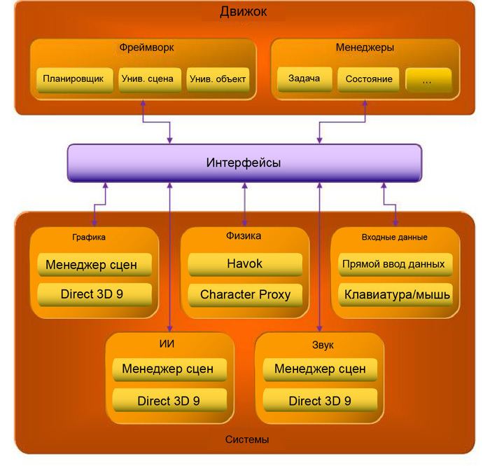
The engine can be divided into two parts: the framework and managers. The framework (see section 3.1) includes parts of the game that are replicated in the process of execution, that is, they exist in several copies. It also includes elements involved in the execution of the main game cycle. Managers (see Section 3.2) are singleton objects responsible for the execution of the logical component of the game.
Below is a diagram of the game engine.
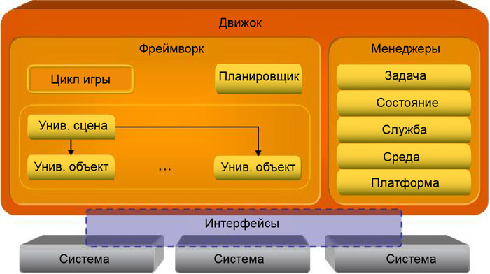
Figure 3. The overall architecture of the engine
Please note that functional game modules, or systems, are not part of the engine. The engine only unites them, acting as a connecting element. Such a modular organization makes it possible to load and unload systems as needed.
The interaction of the engine and systems is carried out using interfaces. They are implemented in such a way as to give the engine access to the functions of the systems, and systems - to the managers of the engine.
A detailed diagram of the engine is presented in Appendix A, “Engine Diagram”.
In fact, all systems are independent of each other (see Section 2, “Simultaneous Execution Status”), that is, they can perform actions in parallel without affecting the work of other systems. However, any change in data will entail certain difficulties, since the systems will have to interact with each other. The exchange of information between systems is necessary in the following cases:
In the first case, the state manager described in the previous section can be used to control the exchange of information. (For details on the state manager, see section 3.2.2, “State Manager”.)
In the second case, you need to implement a special mechanism that allows you to provide the services of one system to use another. A full description of this mechanism is given in Section 3.2.3, “Service Manager”.
The framework is used to combine all the elements of the engine. It is the initialization of the engine, with the exception of managers, instances of which are created globally. It also stores information about the scene. To achieve greater flexibility, the scene is implemented in the form of a so-called universal scene, which contains universal objects. They are containers that combine the various functional parts of the scene. Detailed information is provided in section 3.1.2.
The main game cycle is also implemented in the framework. Schematically it can be represented as follows.
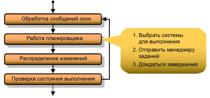
Figure 4. Main game loop
The engine works in a windowed environment, therefore, in the first step of the game cycle, it is necessary to process all incomplete messages of the OS windows. If this is not done, the engine will not respond to OS messages. In the second step, the scheduler assigns tasks using the task manager. This process is described in detail in section 3.1.1 below. After that, the state manager (see Section 3.2.2) sends information about the changes made to the engine systems, the operation of which it can affect. At the last step, depending on the execution status, the framework determines whether to complete or continue the engine, for example, to go to the next scene. Information about the state of the engine is stored in the environment manager. For details, see section 3.2.4.
The scheduler generates a reference clock signal with a specified frequency. If in benchmarking mode it is required that the next operation starts immediately after the previous one is completed, without waiting for the end of the cycle, the frequency can be unlimited.
Using a clock signal, the scheduler with the help of the task manager puts the system into the execution mode. In a free step-by-step mode (section 2.1.1), the scheduler polls the system to determine how many ticks they need to complete the task. According to the survey results, the scheduler determines which systems are ready for execution, and which ones will complete the work at a specific time. The scheduler can change the number of ticks if any system needs more time to execute. In a hard step-by-step mode (section 2.1.2), all systems begin and end execution on the same clock cycle, so the scheduler waits for all systems to finish.
The universal scene and objects are containers for functionality implemented in other systems. They are intended solely to interact with the engine and do not perform any other functions. However, they can be extended to use functions available to other systems. This allows for weak connectivity. Indeed, the universal scene and objects can use the properties of other systems without being attached to them. This property eliminates the dependence of systems from each other and gives them the opportunity to work simultaneously.
The diagram below shows the expansion of the universal scene and object.
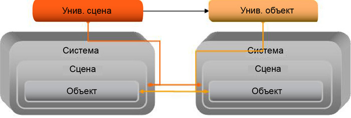
Figure 5. Expansion of the universal scene and object
Consider the principle of the extensions on the following example. Let's say an extension of the universal universal scene has been completed; the scene has been extended to use graphical, physical, and other properties. In this case, the “graphic” part of the expansion will be responsible for the initialization of the display, and its “physical” part will be responsible for implementing the physical laws for solids, such as gravity. Scenes contain objects, so a universal scene will also include several universal objects. Generic objects can also be expanded to be extended to use graphical, physical, and other properties. For example, the drawing of an object on the screen will be realized by graphic functions of expansion, and the calculation of the interaction of solids - by physical ones.
A detailed diagram of the interaction of the engine and systems is given in Appendix B, "The scheme of interaction between the engine and systems."
It should be noted that the universal scene and universal object are responsible for registering all of their "extensions" in the state manager, so that all extensions can be notified of changes made by other extensions (that is, other systems). As an example, a graphic extension registered to receive notifications about changes in position and orientation made by the physical extension.
For detailed information on system components, see Section 5.2, “System Components”.
Managers manage the engine. They are singleton objects, that is, each type of manager is available in only one instance. This is necessary because the duplication of resource managers will inevitably lead to redundancy and will adversely affect performance. In addition, managers are responsible for implementing common functions for all systems.
The task manager is responsible for managing system tasks in the thread pool. To ensure optimal n-fold scaling and prevent the assignment of unnecessary threads, eliminating unnecessary costs for switching tasks in the operating system, a thread pool creates one thread per processor.
The scheduler sends to the task manager a list of tasks to be performed, as well as information on which tasks need to be completed. He receives this data from various systems. Each system receives only one task to perform. This method is called functional decomposition. However, for data processing each such task can be divided into an arbitrary number of subtasks (data decomposition).
Below is an example of the distribution of tasks between threads for a quad-core system.
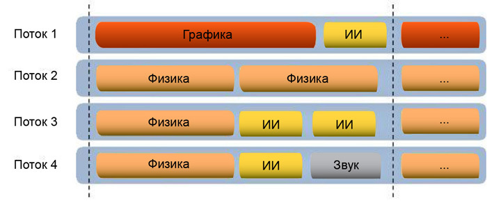
Figure 6. Example thread pool used by task manager
In addition to processing the scheduler's requests for access to the main tasks, the task manager can work in the initialization mode. He sequentially polls the systems from each stream so that they can initialize the local data stores needed for operation.
Tips for implementing a task manager are given in Appendix D, “Tips for Implementing Tasks.”
The state manager is part of the messaging engine. It tracks changes and sends notifications about them to all systems that these changes may affect. In order not to send unnecessary notifications, the state manager stores information about which systems to notify in this or that case. This mechanism is based on the “Observer” template (see Appendix C, “Observer (design pattern)”). In short, this pattern assumes the use of an “observer” who monitors any changes of the subject, and the change controller performs the role of an intermediary between them.
The mechanism works as follows. 1. The observer tells the change controller (or state manager) which changes he wants to monitor. 2. The entity notifies the controller of all its changes. 3. At the signal of the framework, the controller notifies the observer about changes in the subject. 4. The observer sends a request for updated data to the subject.
In the free step-by-step mode (see Section 2.1.1), the implementation of this mechanism is somewhat complicated. First, the updated data will have to be sent along with the change notification. In this mode, sending by request is not applicable. Indeed, if at the time of receiving the request, the system responsible for the changes has not yet completed execution, it will not be able to provide updated data. Secondly, if some system is not yet ready to receive changes at the end of a clock, the state manager will have to hold the changed data until all the systems registered to receive them are in a ready state.
The framework provides for this two state managers: for processing changes at the scene level and at the object level. Typically, messages relating to scenes and objects are independent of each other, so the use of two separate managers eliminates the need to process unnecessary data. But if a scene needs to take into account the state of an object, it can be registered on to receive notifications about its changes.
In order not to perform unnecessary synchronization, the state manager creates a queue of change notifications separately for each thread created by the task manager. Therefore, when accessing the queue, no synchronization is required. Section 2.2 describes a method that can be used to join queues after execution.
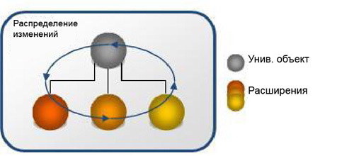
Figure 7. Notification of internal changes to the universal object
Notification of changes is not necessary to send consistently. There is a way to send them in parallel. Performing the task, the system works with all its objects. For example, as physical objects interact with each other, the physical system controls their movement, the calculation of collisions, new forces, etc. When receiving notifications, the system object does not interact with other objects of its system. It interacts with the associated extensions of the universal object. This means that universal objects are now independent of each other and can be updated simultaneously. This approach does not exclude extreme cases that should be considered in the synchronization process. However, it allows the use of parallel execution mode, when it seemed that it was possible to act only consistently.
The service manager provides systems with access to functions of other systems that otherwise would not be available to them. It is important to understand that access to functions is done through interfaces, and not directly. Information about system interfaces is also stored in the service manager.
To eliminate system dependencies from each other, each of them has only a small set of services. In addition, the ability to use a particular service is not determined by the system itself, but by the service manager.
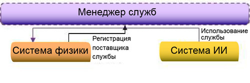
Figure 8. Sample service manager
The service manager has another function. It provides systems with access to the properties of other systems. Properties are specific values of specific systems that are not transmitted in the messaging system. This may be an extension of the screen resolution in the graphics system or the magnitude of gravity in the physical. The service manager provides systems with access to such data, but does not allow direct control over them. It puts the property changes in a special queue and publishes them only after successive execution. Please note that access to the properties of another system is rarely required and should not be abused. For example, it may be necessary to enable or disable the frame grid mode in the graphics system from the console window or to change the screen resolution for a player's request from the user interface. This feature is mainly used to set parameters that do not change from frame to frame.
The platform manager implements an abstraction for calls to the operating system, and also provides additional functionality besides simple abstraction. The advantage of this approach is the encapsulation of several typical functions within a single call. That is, they do not have to be implemented separately for each caller, overloading it with details about the OS calls.
Consider as an example a call to the platform manager to load the system dynamic library. It not only loads the system, but also receives the function entry points and calls the library initialization function. The manager also stores the library descriptor and unloads it after the engine is completed.
The platform manager is also responsible for providing information about the processor, for example, supported SIMD instructions, and for initializing a specific mode of operation of processes. The system cannot use other query functions.
Interfaces are the means of interaction between the framework, managers and systems. The framework and managers are part of the engine, so they can interact with each other directly. Systems to the engine do not apply. Moreover, they all perform different functions, which leads to the need to create a single method of interaction with them. Since systems cannot interact with managers directly, they need to provide another way of access. However, not all functions of managers should be open to systems. Some of them are available only to the framework.
Interfaces define a set of functions required to use the standard access method. This eliminates the need for the framework to know the implementation details of specific systems, since it can interact with them only through a specific set of calls.
The main purpose of the subject and observer interfaces is to register how to send observers notifications about which subjects, as well as sending such notifications. Registration and disconnection with the observer are standard functions for all subjects included in the implementation of their interface.
Managers, despite being singleton objects, are directly accessible only to the framework. Other systems can access managers only through interfaces that represent only a fraction of their overall functionality. After initialization, the interface is transferred to the system, which uses it to work with certain functions of the manager.
There is no single interface for all managers. Each of them has its own separate interface.
In order for the framework to access the components of the system, it needs interfaces. Without them, the support of each new engine system would have to be implemented separately.
Each system includes four components, so there should be four interfaces. Namely: the system, the scene, the object and the task. For a detailed description, see section 5, “Systems”. Interfaces are the means of gaining access to components. System interfaces allow you to create and delete scenes. The scene interfaces, in turn, allow you to create and destroy objects, as well as request information about the main task of the system. The task interface is mainly used by the task manager when setting tasks to the thread pool.
Since the scene and the object, as parts of the system, must interact with each other and with the universal scene and the object to which they are attached, their interfaces are also created on the basis of the subject and the observer interfaces.
These interfaces are used to transfer data between systems. All systems that perform changes of a particular type must implement such an interface. An example is the geometry. The geometry interface includes methods for determining the position, orientation and scale of an element. Any system that makes changes to the geometry must implement such an interface that information about other systems is not required to access the modified data.
Systems are part of the engine, which is responsible for the implementation of gaming functionality. They perform all the basic tasks, without which the engine would have no meaning. The interaction between the engine and systems is carried out using interfaces (see Section 4.3, “System Interfaces”). This is necessary in order not to overload the engine with information about various types of systems. Thanks to the interfaces, the process of adding a new system becomes much easier, because the engine does not need to take into account all the implementation details.
The engine system can be divided into several predefined categories that correspond to the standard components of the game. For example: geometry, graphics, physics (collision of solids), sound, input data processing, AI and animation.
Systems with non-standard features fall into a separate category. It is important to understand that any system that changes data of a specific category must be aware of the interface of this category, since the engine does not provide such information.
For each system it is necessary to implement several components. Here are some of them: system, scene, object and task. All these components are used to interact with different parts of the engine.
The diagram below shows the interactions between the various components.
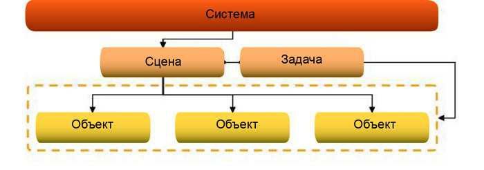
Figure 9. System components
A detailed diagram of the connections between the engine systems is given in Appendix B, "The scheme of interaction between the engine and systems."
The “system” component, or simply the system, is responsible for the initialization of system resources, which will practically not change during the engine operation. For example, the graphics system analyzes the addresses of resources to determine their location and speed up loading when using a resource. It also sets the screen resolution.
The system is the main entry point for the framework. It provides information about itself (for example, the type of system), as well as methods for creating and deleting scenes.
The scene component, or system scene, is responsible for managing the resources that belong to the current scene. The universal scene uses system scenes to extend functionality through the use of their functions. As an example, we can take the physical scene, which is used when creating a new game world and when initializing a scene, determines the gravity forces in it.
The scenes provide methods for creating and destroying objects, as well as the “task” component for processing the scene and the method for accessing it.
The “object” component, or system object, belongs to the scene and is usually associated with what the user sees on the screen. A universal object uses a system object to extend its functionality, providing its properties as its own.
An example would be the geometric, graphical, and physical expansion of a universal object to display a wooden beam on the screen. Geometric properties will include the position, orientation and scale of the object. To display it, the graphics system will use a special grid. A physical system will endow it with the properties of a solid to calculate interactions with other bodies and the acting forces of gravity.
In certain cases in the system object it is necessary to take into account changes in the universal object or one of its extensions. For this purpose, you can create a special link that allows you to track changes made.
The task component, or system task, is used to process the scene. . .
, . . .
. . 3.2.2.
. , .
.
10.
, .
11.
.
12.
, .
. : , , . . «», . «» , . , «», « » .
2, « ». , . , , .
«» — . , . , .
. D .
, . .
(. . 4, « »).

«» « - . », . , . , . , . («Design Patterns: Elements of Reusable Object-Oriented Software», Gamma E., Helm R., Johnson R., Vlissides J.). 1995 Addison-Wesley.
: - , , . , . . . .

13. «»
.
. . . . . , , Threading Building Blocks Intel.
, . .
Consider the features of the implementation of a multi-threaded game engine architecture.
1. Introduction
1.1. Overview
The multi-threaded architecture of the game engine allows you to use the capabilities of all processors of the platform to the maximum. It involves the parallel execution of various functional blocks on all available processors. However, to implement such a scheme, it turns out, is not so simple. Individual elements of the game engine often interact with each other, which can lead to errors when they are executed simultaneously. To handle such scenarios, the engine has special data synchronization mechanisms that exclude possible locks. It also implements methods for simultaneous synchronization of data, thereby minimizing the execution time.
To understand the presented materials, one needs to be well-versed in modern methods of creating computer games, multi-threading support for game engines, or to improve the performance of applications in general.
2. State of parallel execution
The parallel execution state is a key notion of multithreading. Only by dividing the game engine into separate systems, each working in its own mode and practically not interacting with the rest of the engine, one can achieve the highest efficiency of parallel computing and reduce the time required for synchronization. It is not possible to completely isolate separate parts of the engine, excluding all shared resources. However, for operations such as retrieving data on the position or orientation of objects, individual systems may use local copies of data, rather than shared resources. This allows you to minimize the dependence of data in different parts of the engine. Notifications of changes in general data made by a separate system are transmitted to the state manager, which places them in a queue. This is called messaging mode. This mode assumes that, after completing the execution of tasks, the engine systems receive notification of changes and update their internal data accordingly. Such a mechanism can significantly reduce synchronization time and the dependence of systems on each other.
')
2.1 Fulfillment States
In order for the execution state manager to work efficiently, it is recommended to synchronize operations on a certain clock pulse. This allows all systems to operate simultaneously. In this case, the clock frequency does not necessarily have to correspond to the frame rate. Yes, and the duration of the cycles may not depend on the frequency. It can be chosen in such a way that one clock corresponds to the time required to transmit one frame (regardless of its size). In other words, the frequency or duration of clocks is determined by the specific implementation of the state manager. Figure 1 shows the “free” step-by-step mode of operation, in which it is not required that all systems complete the operation in the same clock cycle. The mode in which all systems complete operations in one cycle is called “hard” step-by-step mode. It is schematically depicted in Figure 2.
Figure 1. Run state in step free mode
2.1.1. Free step mode
In free step-by-step mode, all systems operate continuously for a predetermined period of time required to complete the next batch of calculations. However, the name “free” should not be taken literally: the systems are not synchronized at an arbitrary point in time, they are only “free” in the choice of the number of cycles required for the execution of the next stage.
As a rule, in this mode it is not enough to send a simple state change notification to the state manager. You must also transfer the updated data. This is because the system that changed the shared data may be in a running state, while another system that is waiting for this data is ready to perform the update. In this case, more memory is required, since you need to create more copies of the data. Therefore, the “free” regime cannot be considered a universal solution for all occasions.
2.1.2. Hard Step Mode
In this mode, the execution of tasks of all systems is completed in one cycle. Such a mechanism is easier to implement and does not require the transfer of updated data along with the notification. Indeed, if necessary, one system can simply request new values from another system (of course, at the end of the execution cycle).
In hard mode, you can implement a pseudo-free step-by-step mode of operation, distributing the calculations between the various steps. In particular, this may be required for AI calculations, where the initial “common goal” is calculated for the first beat, which is gradually refined in the next stages.
Figure 2. Execute status in hard walk mode
2.2. Data synchronization
Changing shared data across multiple systems may result in a conflict of changes. In this case, in the messaging system it is necessary to provide an algorithm for selecting the correct total value. There are two main approaches based on the following criteria.
- Time: The final value is the last change made.
- Priority: the final value is the change made by the system with the highest priority. If the priority of the systems coincides, you can also consider the time for making changes.
All obsolete data (according to any of the criteria) can be simply overwritten or excluded from the notification queue.
Since the final value may depend on the order of the changes, it can be very difficult to use the relative values of the total data. In such cases, absolute values should be used. Then, when updating local data, systems can simply replace old values with new ones. The optimal solution is to choose absolute or relative values depending on the specific situation. For example, general data, such as position and orientation, should have absolute values, since the order of change is important to them. Relative values can be used, for example, for a particle generation system, since all information about particles is stored only in itself.
3. Engine
When developing the engine, the focus is on the flexibility needed to further expand its functionality. This will optimize it for use under certain restrictions (for example, by memory).
The engine can be divided into two parts: the framework and managers. The framework (see section 3.1) includes parts of the game that are replicated in the process of execution, that is, they exist in several copies. It also includes elements involved in the execution of the main game cycle. Managers (see Section 3.2) are singleton objects responsible for the execution of the logical component of the game.
Below is a diagram of the game engine.
Figure 3. The overall architecture of the engine
Please note that functional game modules, or systems, are not part of the engine. The engine only unites them, acting as a connecting element. Such a modular organization makes it possible to load and unload systems as needed.
The interaction of the engine and systems is carried out using interfaces. They are implemented in such a way as to give the engine access to the functions of the systems, and systems - to the managers of the engine.
A detailed diagram of the engine is presented in Appendix A, “Engine Diagram”.
In fact, all systems are independent of each other (see Section 2, “Simultaneous Execution Status”), that is, they can perform actions in parallel without affecting the work of other systems. However, any change in data will entail certain difficulties, since the systems will have to interact with each other. The exchange of information between systems is necessary in the following cases:
- to inform another system about changes in general data (for example, the position or orientation of objects);
- to perform functions that are not available for this system (for example, the AI system refers to the system for calculating the geometric or physical properties of an object in order to perform a ray intersection test).
In the first case, the state manager described in the previous section can be used to control the exchange of information. (For details on the state manager, see section 3.2.2, “State Manager”.)
In the second case, you need to implement a special mechanism that allows you to provide the services of one system to use another. A full description of this mechanism is given in Section 3.2.3, “Service Manager”.
3.1. Framework
The framework is used to combine all the elements of the engine. It is the initialization of the engine, with the exception of managers, instances of which are created globally. It also stores information about the scene. To achieve greater flexibility, the scene is implemented in the form of a so-called universal scene, which contains universal objects. They are containers that combine the various functional parts of the scene. Detailed information is provided in section 3.1.2.
The main game cycle is also implemented in the framework. Schematically it can be represented as follows.
Figure 4. Main game loop
The engine works in a windowed environment, therefore, in the first step of the game cycle, it is necessary to process all incomplete messages of the OS windows. If this is not done, the engine will not respond to OS messages. In the second step, the scheduler assigns tasks using the task manager. This process is described in detail in section 3.1.1 below. After that, the state manager (see Section 3.2.2) sends information about the changes made to the engine systems, the operation of which it can affect. At the last step, depending on the execution status, the framework determines whether to complete or continue the engine, for example, to go to the next scene. Information about the state of the engine is stored in the environment manager. For details, see section 3.2.4.
3.1.1. Scheduler
The scheduler generates a reference clock signal with a specified frequency. If in benchmarking mode it is required that the next operation starts immediately after the previous one is completed, without waiting for the end of the cycle, the frequency can be unlimited.
Using a clock signal, the scheduler with the help of the task manager puts the system into the execution mode. In a free step-by-step mode (section 2.1.1), the scheduler polls the system to determine how many ticks they need to complete the task. According to the survey results, the scheduler determines which systems are ready for execution, and which ones will complete the work at a specific time. The scheduler can change the number of ticks if any system needs more time to execute. In a hard step-by-step mode (section 2.1.2), all systems begin and end execution on the same clock cycle, so the scheduler waits for all systems to finish.
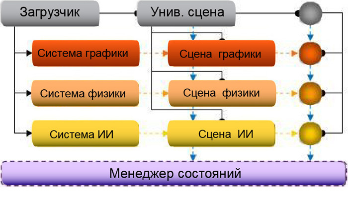
3.1.2. Universal Scene and Objects
The universal scene and objects are containers for functionality implemented in other systems. They are intended solely to interact with the engine and do not perform any other functions. However, they can be extended to use functions available to other systems. This allows for weak connectivity. Indeed, the universal scene and objects can use the properties of other systems without being attached to them. This property eliminates the dependence of systems from each other and gives them the opportunity to work simultaneously.
The diagram below shows the expansion of the universal scene and object.
Figure 5. Expansion of the universal scene and object
Consider the principle of the extensions on the following example. Let's say an extension of the universal universal scene has been completed; the scene has been extended to use graphical, physical, and other properties. In this case, the “graphic” part of the expansion will be responsible for the initialization of the display, and its “physical” part will be responsible for implementing the physical laws for solids, such as gravity. Scenes contain objects, so a universal scene will also include several universal objects. Generic objects can also be expanded to be extended to use graphical, physical, and other properties. For example, the drawing of an object on the screen will be realized by graphic functions of expansion, and the calculation of the interaction of solids - by physical ones.
A detailed diagram of the interaction of the engine and systems is given in Appendix B, "The scheme of interaction between the engine and systems."
It should be noted that the universal scene and universal object are responsible for registering all of their "extensions" in the state manager, so that all extensions can be notified of changes made by other extensions (that is, other systems). As an example, a graphic extension registered to receive notifications about changes in position and orientation made by the physical extension.
For detailed information on system components, see Section 5.2, “System Components”.
3.2. Managers
Managers manage the engine. They are singleton objects, that is, each type of manager is available in only one instance. This is necessary because the duplication of resource managers will inevitably lead to redundancy and will adversely affect performance. In addition, managers are responsible for implementing common functions for all systems.
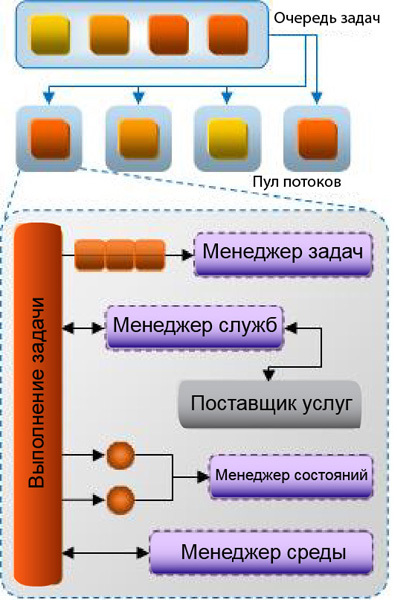
3.2.1. Task manager
The task manager is responsible for managing system tasks in the thread pool. To ensure optimal n-fold scaling and prevent the assignment of unnecessary threads, eliminating unnecessary costs for switching tasks in the operating system, a thread pool creates one thread per processor.
The scheduler sends to the task manager a list of tasks to be performed, as well as information on which tasks need to be completed. He receives this data from various systems. Each system receives only one task to perform. This method is called functional decomposition. However, for data processing each such task can be divided into an arbitrary number of subtasks (data decomposition).
Below is an example of the distribution of tasks between threads for a quad-core system.
Figure 6. Example thread pool used by task manager
In addition to processing the scheduler's requests for access to the main tasks, the task manager can work in the initialization mode. He sequentially polls the systems from each stream so that they can initialize the local data stores needed for operation.
Tips for implementing a task manager are given in Appendix D, “Tips for Implementing Tasks.”
3.2.2. State manager
The state manager is part of the messaging engine. It tracks changes and sends notifications about them to all systems that these changes may affect. In order not to send unnecessary notifications, the state manager stores information about which systems to notify in this or that case. This mechanism is based on the “Observer” template (see Appendix C, “Observer (design pattern)”). In short, this pattern assumes the use of an “observer” who monitors any changes of the subject, and the change controller performs the role of an intermediary between them.
The mechanism works as follows. 1. The observer tells the change controller (or state manager) which changes he wants to monitor. 2. The entity notifies the controller of all its changes. 3. At the signal of the framework, the controller notifies the observer about changes in the subject. 4. The observer sends a request for updated data to the subject.
In the free step-by-step mode (see Section 2.1.1), the implementation of this mechanism is somewhat complicated. First, the updated data will have to be sent along with the change notification. In this mode, sending by request is not applicable. Indeed, if at the time of receiving the request, the system responsible for the changes has not yet completed execution, it will not be able to provide updated data. Secondly, if some system is not yet ready to receive changes at the end of a clock, the state manager will have to hold the changed data until all the systems registered to receive them are in a ready state.
The framework provides for this two state managers: for processing changes at the scene level and at the object level. Typically, messages relating to scenes and objects are independent of each other, so the use of two separate managers eliminates the need to process unnecessary data. But if a scene needs to take into account the state of an object, it can be registered on to receive notifications about its changes.
In order not to perform unnecessary synchronization, the state manager creates a queue of change notifications separately for each thread created by the task manager. Therefore, when accessing the queue, no synchronization is required. Section 2.2 describes a method that can be used to join queues after execution.
Figure 7. Notification of internal changes to the universal object
Notification of changes is not necessary to send consistently. There is a way to send them in parallel. Performing the task, the system works with all its objects. For example, as physical objects interact with each other, the physical system controls their movement, the calculation of collisions, new forces, etc. When receiving notifications, the system object does not interact with other objects of its system. It interacts with the associated extensions of the universal object. This means that universal objects are now independent of each other and can be updated simultaneously. This approach does not exclude extreme cases that should be considered in the synchronization process. However, it allows the use of parallel execution mode, when it seemed that it was possible to act only consistently.
3.2.3. Service Manager
The service manager provides systems with access to functions of other systems that otherwise would not be available to them. It is important to understand that access to functions is done through interfaces, and not directly. Information about system interfaces is also stored in the service manager.
To eliminate system dependencies from each other, each of them has only a small set of services. In addition, the ability to use a particular service is not determined by the system itself, but by the service manager.
Figure 8. Sample service manager
The service manager has another function. It provides systems with access to the properties of other systems. Properties are specific values of specific systems that are not transmitted in the messaging system. This may be an extension of the screen resolution in the graphics system or the magnitude of gravity in the physical. The service manager provides systems with access to such data, but does not allow direct control over them. It puts the property changes in a special queue and publishes them only after successive execution. Please note that access to the properties of another system is rarely required and should not be abused. For example, it may be necessary to enable or disable the frame grid mode in the graphics system from the console window or to change the screen resolution for a player's request from the user interface. This feature is mainly used to set parameters that do not change from frame to frame.
3.2.4. Environment manager
- The environment manager provides an engine runtime environment. Its functions can be divided into the following groups.
- Variables: the names and values of common variables used by all parts of the engine. Usually, the values of variables are determined when loading a scene or certain user settings. The engine and various systems can access them by sending an appropriate request.
- Execution: information about the execution, such as the completion of a scene or program. These parameters can set and request both the systems themselves and the engine.
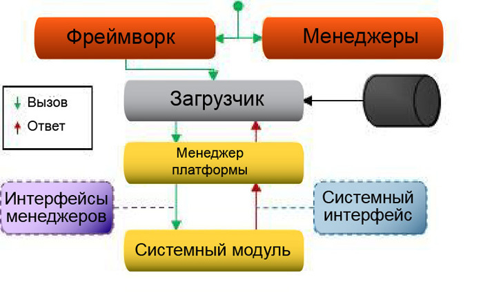
3.2.5. Platform manager
The platform manager implements an abstraction for calls to the operating system, and also provides additional functionality besides simple abstraction. The advantage of this approach is the encapsulation of several typical functions within a single call. That is, they do not have to be implemented separately for each caller, overloading it with details about the OS calls.
Consider as an example a call to the platform manager to load the system dynamic library. It not only loads the system, but also receives the function entry points and calls the library initialization function. The manager also stores the library descriptor and unloads it after the engine is completed.
The platform manager is also responsible for providing information about the processor, for example, supported SIMD instructions, and for initializing a specific mode of operation of processes. The system cannot use other query functions.
4. Interfaces
Interfaces are the means of interaction between the framework, managers and systems. The framework and managers are part of the engine, so they can interact with each other directly. Systems to the engine do not apply. Moreover, they all perform different functions, which leads to the need to create a single method of interaction with them. Since systems cannot interact with managers directly, they need to provide another way of access. However, not all functions of managers should be open to systems. Some of them are available only to the framework.
Interfaces define a set of functions required to use the standard access method. This eliminates the need for the framework to know the implementation details of specific systems, since it can interact with them only through a specific set of calls.
4.1. Subject and Observer Interfaces
The main purpose of the subject and observer interfaces is to register how to send observers notifications about which subjects, as well as sending such notifications. Registration and disconnection with the observer are standard functions for all subjects included in the implementation of their interface.
4.2. Manager Interfaces
Managers, despite being singleton objects, are directly accessible only to the framework. Other systems can access managers only through interfaces that represent only a fraction of their overall functionality. After initialization, the interface is transferred to the system, which uses it to work with certain functions of the manager.
There is no single interface for all managers. Each of them has its own separate interface.
4.3. System interfaces
In order for the framework to access the components of the system, it needs interfaces. Without them, the support of each new engine system would have to be implemented separately.
Each system includes four components, so there should be four interfaces. Namely: the system, the scene, the object and the task. For a detailed description, see section 5, “Systems”. Interfaces are the means of gaining access to components. System interfaces allow you to create and delete scenes. The scene interfaces, in turn, allow you to create and destroy objects, as well as request information about the main task of the system. The task interface is mainly used by the task manager when setting tasks to the thread pool.
Since the scene and the object, as parts of the system, must interact with each other and with the universal scene and the object to which they are attached, their interfaces are also created on the basis of the subject and the observer interfaces.
4.4. Change Interfaces
These interfaces are used to transfer data between systems. All systems that perform changes of a particular type must implement such an interface. An example is the geometry. The geometry interface includes methods for determining the position, orientation and scale of an element. Any system that makes changes to the geometry must implement such an interface that information about other systems is not required to access the modified data.
5. Systems
Systems are part of the engine, which is responsible for the implementation of gaming functionality. They perform all the basic tasks, without which the engine would have no meaning. The interaction between the engine and systems is carried out using interfaces (see Section 4.3, “System Interfaces”). This is necessary in order not to overload the engine with information about various types of systems. Thanks to the interfaces, the process of adding a new system becomes much easier, because the engine does not need to take into account all the implementation details.
5.1. Types
The engine system can be divided into several predefined categories that correspond to the standard components of the game. For example: geometry, graphics, physics (collision of solids), sound, input data processing, AI and animation.
Systems with non-standard features fall into a separate category. It is important to understand that any system that changes data of a specific category must be aware of the interface of this category, since the engine does not provide such information.
5.2. System components
For each system it is necessary to implement several components. Here are some of them: system, scene, object and task. All these components are used to interact with different parts of the engine.
The diagram below shows the interactions between the various components.
Figure 9. System components
A detailed diagram of the connections between the engine systems is given in Appendix B, "The scheme of interaction between the engine and systems."
5.2.1. System
The “system” component, or simply the system, is responsible for the initialization of system resources, which will practically not change during the engine operation. For example, the graphics system analyzes the addresses of resources to determine their location and speed up loading when using a resource. It also sets the screen resolution.
The system is the main entry point for the framework. It provides information about itself (for example, the type of system), as well as methods for creating and deleting scenes.
5.2.2. Scene
The scene component, or system scene, is responsible for managing the resources that belong to the current scene. The universal scene uses system scenes to extend functionality through the use of their functions. As an example, we can take the physical scene, which is used when creating a new game world and when initializing a scene, determines the gravity forces in it.
The scenes provide methods for creating and destroying objects, as well as the “task” component for processing the scene and the method for accessing it.
5.2.3. An object
The “object” component, or system object, belongs to the scene and is usually associated with what the user sees on the screen. A universal object uses a system object to extend its functionality, providing its properties as its own.
An example would be the geometric, graphical, and physical expansion of a universal object to display a wooden beam on the screen. Geometric properties will include the position, orientation and scale of the object. To display it, the graphics system will use a special grid. A physical system will endow it with the properties of a solid to calculate interactions with other bodies and the acting forces of gravity.
In certain cases in the system object it is necessary to take into account changes in the universal object or one of its extensions. For this purpose, you can create a special link that allows you to track changes made.
5.2.4. Task
The task component, or system task, is used to process the scene. . .
, . . .
. . 3.2.2.
6.
. , .
6.1.
.
- .
- , , .
- , .
- , .
- , .
10.
6.2.
, .
- . , , .
- , .
- , , .
- , , . , . .
- .
- , .
11.
6.3.
- , .
- , , .
- , . ( ) .
- , , .
- . .
6.3.1.
.
- , , , . ( . , .)
- , .
- (, ). . , .
- . , .
- , . , (, — ).
- ( , .).
12.
6.3.2.
, .
- . , .
- ( ). , .
- , , , . , . , .
6.3.3.
. : , , . . «», . «» , . , «», « » .
7.
2, « ». , . , , .
«» — . , . , .
. D .
, . .
A.
(. . 4, « »).
B.
C. ( )
«» « - . », . , . , . , . («Design Patterns: Elements of Reusable Object-Oriented Software», Gamma E., Helm R., Johnson R., Vlissides J.). 1995 Addison-Wesley.
: - , , . , . . . .
13. «»
.
- , .
- . . .
- ( ) , . , , . .
- , .
- .
- .
- ( ).
- , .
D.
. . . . . , , Threading Building Blocks Intel.
, . .
- Reverse feed. If the order of the main tasks practically does not change, for each next frame they can be assigned in the reverse order. It is highly likely that the data from the last task performed in the previous frame is still in the cache. That is, performing tasks in reverse order eliminates the need to overwrite the data in the CPU cache.
- Shared cache: in some multi-core processors, the cache is divided into sections. Thus, one pair of processors can use one part of the common cache, and the other - the other. Such a model increases the likelihood that when assigning subtasks to the same system, the necessary data will already be in the shared cache.
Source: https://habr.com/ru/post/266427/
All Articles