Magnetic core memory module in an IBM 1401 vintage mainframe
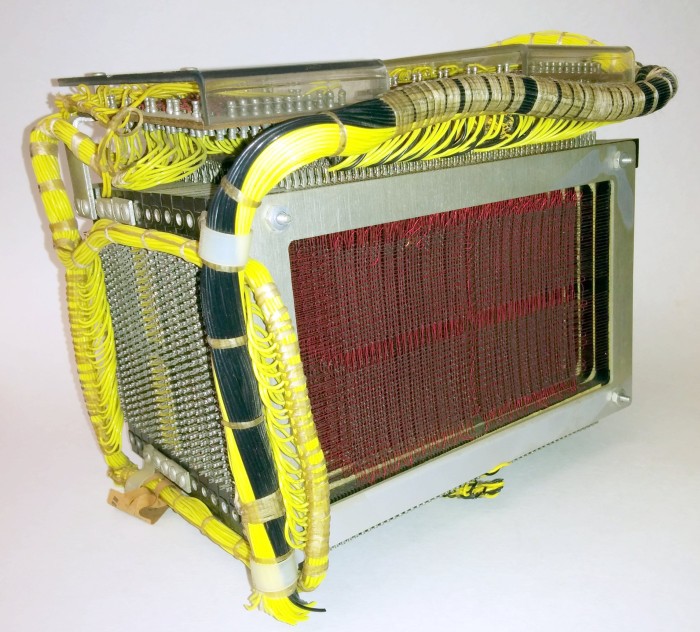
4000 character ferrite memory module in IBM 1401 mainframe
The IBM 1401 mainframe was introduced in 1959, and by the mid-60s it had become the most popular computer in the world , far ahead of the competition. In particular, he used the medium and large businesses, because of its low cost. The key success factor to the 1401 was its memory on magnetic cores (ferrite memory) per 4000 characters, where data was stored on tiny magnetized ferrite rings - cores.
The memory module (see photo above) is surprisingly complex, with thousands of small cores mounted on red wiring. In this article, we delve into his device in detail.
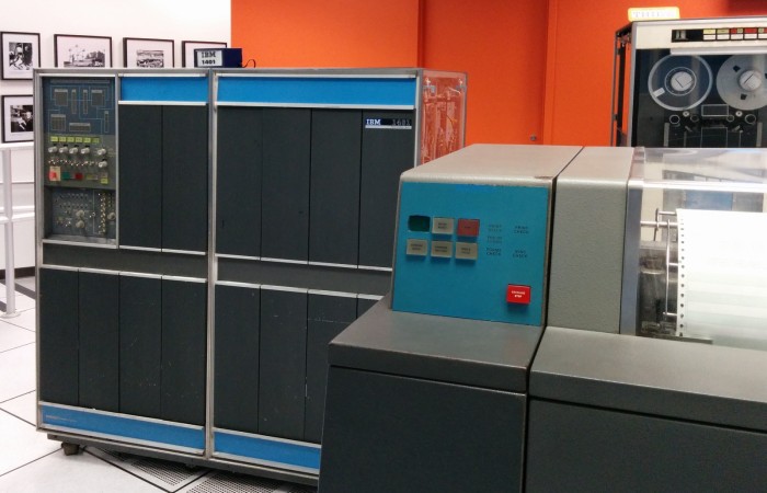
IBM 1401 mid-60s mainframe. On the right line printer 1403, in the background the tape drive 792
')
The IBM 1401 mainframe is about the size of two refrigerators. To get to the memory module, you need to open the front door, as shown below. Console switches, light bulbs and wires are left. The memory module itself is in the center, mostly covered with a brown printed circuit board.
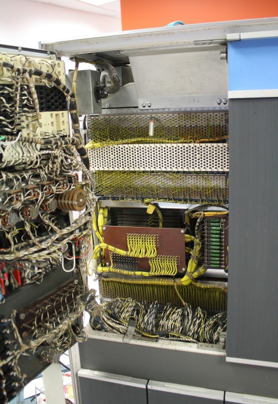
Opening the panel (left) on the 1401 mainframe, we see a memory module on magnetic cores (center)
The diagram below shows how the 'A' symbol is stored in memory. Each bit in the memory corresponds to its ferrite ring or core. These cores can be magnetized in one or two directions, which corresponds to bit 0 or 1. The cores are grouped into a lattice of 4,000 pieces, which is called a “plane”. To access a specific address, wires X and Y are activated, choosing a core that is at their intersection. Each level stores one bit of data at a given address, and they are stacked to store one character. You can assume that 8 levels are used to store a byte, but the IBM 1401 was created before the ubiquitous use of bytes and uses 6-bit characters on binary-coded decimal code (BCD, binary-coded decimal). Each location also stores a bit of special metadata, which is called a “word mark,” corresponding to the beginning of the field or instruction. Add a parity bit - and get the storage for eight bits at each address.
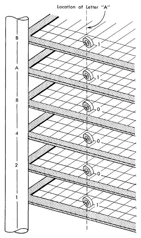
The diagram in the reference manual shows how the character 'A' is stored in memory.
Since the IBM 1401 was a business computer, he used decimal arithmetic, not binary; each character is a binary-decimal code, along with two additional “zone bits” for alphanumeric characters. The mainframe used addresses from three digits, it would seem, it can get access only to one thousand locations. But the trick is that two bits of the zone for the discharge of hundreds gave a thousandth digit from 0 to 3. As a result, addresses above 1000 became alphanumeric instead of digital; 2345 location was designated as L45.
Properties of ferrite cores
The physical properties of ferrite cores are critical to the functioning of memory, so it is very important to understand them. First, if a strong current passes through the core through the core, the core will be magnetized in accordance with the direction of the current (according to the crawl rule ). A current in one direction will write “one” into the core, a current in the opposite direction will cause the opposite magnetization and write “zero” into the core.
Hysteresis is a key property of the core: the current must exceed a certain threshold in order to affect the magnetization of the core. A small current will have no effect, but a current above the threshold will lead to a “click” with a transition to the magnetized state in accordance with the direction of the current.
Close-up of IBM 1401 ferrite cores with 4K memory. Four wires pass through each core: two excitation wires X and Y, S (sense, read wire) and Z (inhibit, wire ban)
The hysteresis property makes it possible to select a particular core. The “half” current is directed through the appropriate excitation wire X, and the “half” current through the corresponding excitation wire Y. Thus, only a single core among thousands of others will receive a current sufficient to change its state.
The last important property is that when the core changes the direction of magnetization, it induces a current in the read wire passing through this core. If the direction of magnetization does not change, then there is no current there. This induced current is used to read the state of a bit of memory. As a result, when reading information from the core, the information is erased and must be overwritten.
Core Level Structure
Each level consists of 4000 cores located in a 50x80 grid. To reduce pickups, ferrite cores are arranged in a checkerboard pattern, where each core is located diagonally in the opposite direction from its neighbors. Four wires run through each of them. Horizontal wires are the excitation wires X and the inhibit wires Z, which are used for recording. The vertical wires are the excitation wires Y and the sense wires S. The excitation wires X and Y go through all levels, so that all levels are accessible in parallel.
IBM 1401 ferrite memory. Each level contains 4000 cores in the 80x50 grid
To read the state of the memory bit, the excitation wires X and Y magnetize the selected cores in the “0” direction. If the core was previously in the “1” state, then a state change induces a current in the reading wire S. If the core was already in the “0” state, no current is induced. Thus, the read wire allows you to determine which bit is stored in memory. The reading procedure destroys the previous state of the core, putting it in the state "0". At each level there is a wire reader, stretched across all level cores.
To record information, the current in the opposite direction is directed through the excitation wires X and Y to magnetize the core to the state "1". In order to keep the core in the “0” state, the current is directed along a wire prohibiting this level. The inhibit wire passes through all the cores of the level parallel to the excitation wires X. If there is current in the opposite direction in the inhibit wire, the current in the conductor X is compensated and the state of the core remains unchanged. The inhibit current is too small to change the state of the bit itself, so that the other cores are not reset.
The diagram below shows the topology of the level in the memory module on the IBM 1401 magnetic cores. Most cores are cut from the diagram, as indicated by the gray dotted lines. The sides of the level are marked with letters from A to D, in accordance with documentation 140. There are 56 contacts on sides A and C, while 104 contacts on sides B and D. Not all contacts are connected.
Topology of wires in the level of the memory module on the magnetic cores IBM 1401
The excitation wires X are green and the excitation wires Y are red. The excitation wires are controlled in a complex way via matrix switches , so that the addresses of the cores are not arranged sequentially. Each matrix switch receives two sets of incoming lines and activates the outgoing current, depending on the incoming values. The 5x10 matrix switchboard of excitation wires X has five incoming lines horizontally and ten incoming lines vertically, yielding 50 outgoing values that correspond to the excitation wires X. Ten incoming lines vertically correspond to the unit ones, and five horizontal ones to the even hundreds digit.
The 8x10 matrix switch of the Y excitation wires has eight incoming lines horizontally and ten incoming lines vertically, yielding 80 outgoing values that correspond to the excitation wires Y. thousand.
The scheme may seem too complicated, but it minimizes the amount of equipment needed to decode addresses in memory.
Each half of the level (0-1999 and 2000-3999) is equipped with a separate loop of the reading wire, but usually they are connected together. The two read wires are shown in blue and installed in the Y direction. The read wires are neatly arranged so as not to suffer from interference. The wires intersect in the middle to cancel the pickups from the excitation wires Y - the read wires run in the opposite direction along half of each excitation wire Y, so any induced signal is nullified. In addition, the sensing wires are twisted at the exit from the middle of the level to avoid interference. (Many other memory systems on magnetic cores avoid interference due to the length of the read wires diagonally, but in 1401 a rectangular layout is used).
On each half of the level there is a separate wire ban. Two wires of the ban are shown in brown and pass next to the excitation wires X, which they should block. Two wires are usually controlled separately to reduce interference, but they have the same signal. Since the ban wires change direction in each row, the alternative excitation wires X also have a different current direction in each row.
How magnetic core memory is mounted in the mainframe
The following photo shows a rack-mounted memory module along with a large number of transistor boards ( SMS cards ) that are needed for its operation. Each of the SMS (Standard Modular System) cards, the size of a deck of playing cards, contains several transistors and other components. On the left - DKA and AQW cards for matrix switches, as well as AQV cards for wire barring. In the next column are maps for decoding addresses. In the third column are the WX and AQX cards for excitation wires. Next, the memory module itself is attached with matrix switches on top.
IBM 1401 Mainframe Memory and Memory Module
In the photo below, the memory module is installed inside the mainframe, in front of it hangs a bunch of black and yellow wires, mainly address ones. Matrix switches on the left.
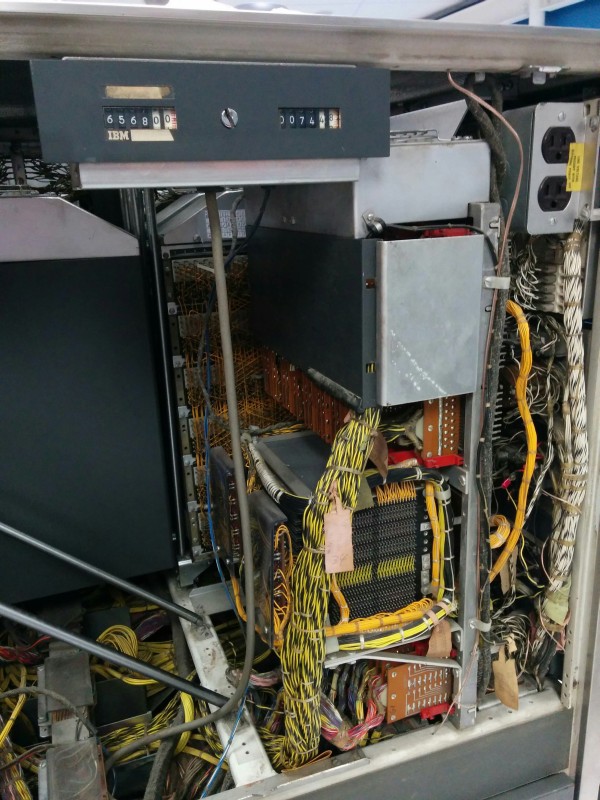
By the way, one of the interesting features of the 1401 is noticeable in the photo. A counter is installed on the computer at the top, which records the operating time of the computer. IBM usually leased the mainframe on the condition that it was used no more than eight hours a day, otherwise it would have to be paid in addition. (Of course, if you only initially did not choose the rate 24/7).
In the upper right corner you can see the power outlet - the usual electrical outlet, but installed inside the computer.
Conclusion
Magnetic core memory has been the leading memory technology since the mid-50s, until semiconductor memory supplanted it in the early 70s. For its time, ferrite memory provided a compact, reliable and inexpensive data storage, but since then technologies have taken a significant step forward. In the memory of the 1401 mainframe, the machine cycle speed was 11.5 microseconds, compared with 5 nanoseconds in modern RAM. The memory capacity was 4K (expanded to 16K), and in modern computers it is measured in gigabytes. Upgrading the mainframe with the addition of another 4K module cost $ 20,100 ($ 162,000 for modern dollars). Now the 16 gigabyte module costs less than a hundred dollars. Despite everything, outdated memory on magnetic cores is an interesting technology to learn.
The author is grateful for the help of the participants of the restoration group 1401 and the staff of the Computer History Museum in California, where this rarity is exhibited to the public on Wednesdays and Saturdays .
Translation published with abbreviations
Source: https://habr.com/ru/post/266425/
All Articles