Qt Augmented Reality
Now augmented reality is one of the most interesting directions. That's why I took up the study, and the result was my own implementation of cross-platform markerless augmented reality on Qt. This article is about how it was implemented (or how to implement it yourself). Under the cut, you can find a demo and a link to the project on the githaba.
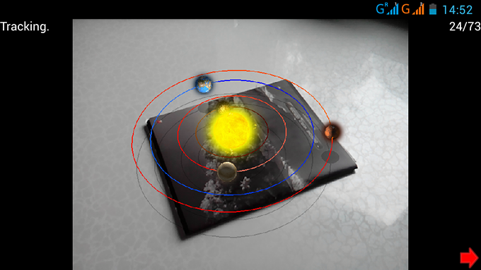
For the operation of augmented reality does not require any markers, any picture will do. It is only necessary to perform initialization: point the camera at a point on the picture, press the start button and move the camera around the selected point.
Here you can download demos for Windows and Android (for some reason it does not work on windows 10).
about the project
The project is divided into three parts:
AR is all about augmented reality. Everything is hidden in the namespace AR, ARSystem - the main object of the system, in which all calculations are carried out.
QScrollEngine is a graphics engine for Qt. Is in the namespace - QScrollEngine. There is a separate project on the githaba .
')
App - actually described here is an application using the augmented reality system and the graphics engine.
Everything described below is based on the PTAM and SVO projects : Fast Semi-Direct Monocular Visual Odometry .
Input data
Our input data is a video stream. By video stream, in this case, we mean a sequence of frames, where information from frame to frame does not change very much (which allows us to determine the correspondence between frames).
Qt has defined classes for working with a video stream, but they do not work on mobile platforms. But you can make it work. It describes how, in this article I will not dwell on this.
General work algorithm
Most often, for the work of augmented reality, some markers are used to help determine the position of the camera in space. This limits its use, because, firstly, the markers must be constantly in the frame, and secondly, they must first be prepared (printed out). However, there is an alternative - the structure from motion technique, in which the data on the camera position are found only by the movement of image points through the frames of the video stream.
It is difficult to work with all points of the image at once (although it is quite possible ( DTAM )), but to work on mobile platforms you need to simplify. Therefore, we will simply select individual “special” points on the image and monitor their movements. Find "special" points in different ways . I used FAST. This algorithm has a disadvantage - it only finds angles of a given size (9, 10 pixels). In order to find points of different scale, a pyramid of images is used. In short, the image pyramid is a set of images, where the first image (base) is the original image, and the next image is two times smaller. Finding singular points at different levels of the pyramid, we find “special” points of different scale. And the pyramid itself is also used in the optical flow to obtain the trajectories of the movements of our points. You can read about it here and here .
So, we have the trajectories of the points and now we need to somehow determine the position of the camera in space. To do this, as can be understood from the application, first initialization is performed on two frames in which the camera is directed at approximately the same point, only at different angles. At this moment, the position of the camera in these frames and the position of “special” points are calculated. Further, using the known three-dimensional coordinates of points, you can already calculate the camera positions in each subsequent frame of the video stream. For more stable operation, we add new points to the tracking process, making a map of the space that the camera sees.
Converting to screen coordinates
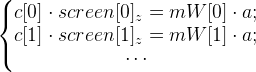
To begin with, let's look at how the three-dimensional coordinates of “special” points pass into screen ones. For this we use this formula (we denote it as formula 1):

world [i] are “special” points in world coordinates. In order not to complicate your life, suppose that these coordinates do not change throughout the time. Prior to initialization, these coordinates are not known.
screen [i] - the x and y components are the coordinates of the “singular” point in the image (they are given by the optical flow), z is the depth relative to the camera. All these coordinates will already be their own on each frame of the video stream.
mProj is a 3 by 3 projection matrix and looks like
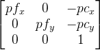 , here pf is the focal distance of the camera in pixels, pc is the optical center of the camera also in pixels (usually approximately the center of the image). It is clear that this matrix should be formed under the parameters of the camera (its viewing angle).
mWorld is a matrix describing the transformation of 3 by 4 points (i.e. the last world matrix from which the last line was removed ( 0 0 0 1 ). This matrix contains information on camera movement and rotation. And this is what we are primarily looking at every frame.
In this case, the distortion is not taken into account, but we will assume that it has almost no effect, and it can be neglected.
We can simplify the formula by getting rid of the mProj matrix (in formula 1):

 .
.We introduce
 which we consider in advance. Then formula 1 is simplified to
  (let it be formula 2).
Initialization
As already mentioned, initialization occurs in two frames. Let's designate them as A and B. So we will have matrices
 and
and  . Points c [i] on frames A and B are denoted as cA [i] and cB [i] . Since we are free to choose the origin, let us assume that the camera in frame A is just there, therefore - this is the identity matrix (only in 3 by 4 size). But the matrix will still have to calculate. And it can be done with the help of points located on one plane. For them, the following formula will be true:
 where the matrix H is a flat homography .
Rewrite the expression in this way (removing the index i for clarity):
And now we turn to this view, getting rid of
 :
:
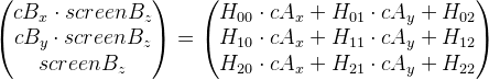
Representing the matrix H as a vector
 , we can present these equations in matrix form:
 .
.Let's denote the new matrix as M. We get M * H ' = 0. All this was written for only one point, therefore there are only 2 rows in the matrix M. In order to find the matrix H ' , it is necessary that the matrix M has the number of rows greater than or equal to the number of columns. If we have only four points, then we can simply add another line of zeros, a 9 by 9 matrix will come out. Then, using a singular decomposition, we find the vector H ' (by itself, it should not be zero). The vector H ' is, as we recall, the vector representation of the matrix H , so that we now have this matrix.
But as mentioned above, all this is true only for points located on the same plane. And which of them are located and which are not, we do not know in advance, but we can assume using the Ransac method in this way:
- In a loop, with a predetermined number of iterations (say 500), perform the following actions:
- Randomly select four pairs of points of frames A and B.
- Find the matrix H.
- Consider how many points give an error less than the specified value, i.e., let
 and then the condition -
 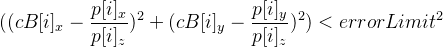 .
.
- Choose H at the iteration in which the most points are obtained.
The H matrix can be obtained using the function from the OpenCV library - cvFindHomography.
From matrix H, we now obtain the position transition matrix from frame A to frame B and call it mMotion .
To begin with, we perform the singular decomposition of the matrix H. We get three matrices:
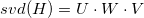 . We introduce in advance some values:
 - in the end, should be equal to ± 1;

Arrays (well, or vector), indicating the desired character:

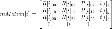
And then we can get 8 possible options for mMotion :

 ;
; where R [i] is the rotation matrix,
t [i] is the displacement vector.
And matrices
 . The parameter i = 0, ..., 7, and accordingly we get 8 variants of the mMotion matrix.
In general, we have the following relation:
= mMotion [i] * , because - this is the identity matrix, it comes out = mMotion [i] .It remains to choose one matrix of 8 mMotion [i] . It is clear that if rays are released from the points of the first and second frames, they must intersect, and in front of the camera, both in the first and in the second case. So, we count the number of intersection points in front of the camera in the first and in the second frame using the resulting mMotion [i] , and discard options for which the number of points will be smaller. Leaving a couple of matrices in the end, choose the one that gives less errors.
So, we have matrices
and , now knowing them you can find the world coordinates of the points by their projections.Calculation of world coordinates of a point by several projections
It would be possible to use the least squares method, but in practice the following method worked better for me:
Let's go back to formula 2. We need to find the point world , which we denote as a . Suppose we have frames in which the mWorld matrices are known (we denote them as mW [0], mW [1], ... ) and the coordinates of the projections of the point a are known (take immediately from [0], from [1], ... ).
And then we have the following system of equations:
But you can imagine them in this form, getting rid of
 (just like they did before):
 where s is any non-zero number,
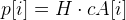
 - system of equations in matrix form. T is known, f is necessary to calculate to find a.
Solving this equation using a singular value decomposition (as well as H 'was found), we obtain the vector f . And accordingly the point
 .
.Calculating the camera position using known world coordinates of points
An iterative algorithm is used. The initial approximation is the previous result of the determination. At each iteration:
- We carry more points
 . Ideally, the points c [i] should be equal to the points b [i] , since the current mWorld approximation is only as long as the approximation (plus other computation errors), they will differ. Calculate the error vector as follows:
 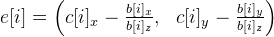 . Solve the system of equations using the least squares method:
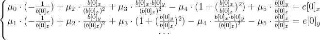
Find the necessary six-dimensional vector - vector exhibitors.
 - Find the displacement matrix of the vector : dT = exp_transformMatrix (mu).The code for this function is:
TMatrix exp_transformMatrix(const TVector& mu) { // mu - 6- TMatrix result(4, 4);// 4 4 static const float one_6th = 1.0f / 6.0f; static const float one_20th = 1.0f / 20.0f; TVector w = mu.slice(3, 3);// 3 mu TVector mu_3 = mu.slice(0, 3);// 3 mu float theta_square = dot(w, w);//dot - float theta = std::sqrt(theta_square); float A, B; TVector crossVector = cross3(w, mu.slice(3));//cross3 2 3- if (theta_square < 1e-4) { A = 1.0f - one_6th * theta_square; B = 0.5f; result.setColumn(3, mu_3 + 0.5f * crossVector);// 4 } else { float C; if (theta_square < 1e-3) { C = one_6th * (1.0f - one_20th * theta_square); A = 1.0f - theta_square * C; B = 0.5f - 0.25f * one_6th * theta_square; } else { float inv_theta = 1.0f / theta; A = std::sin(theta) * inv_theta; B = (1.0f - std::cos(theta)) * (inv_theta * inv_theta); C = (1.0f - A) * (inv_theta * inv_theta); } result.setColumn(3, mu_3 + B * crossVector + C * cross3(w, crossVector)); } exp_rodrigues(result, w, A, B); result(3, 0) = 0.0f; result(3, 1) = 0.0f; result(3, 2) = 0.0f; result(3, 3) = 1.0f; return result; } void exp_rodrigues(TMatrix& result, const TVector& w, float A, float B) { float wx2 = w(0) * w(0); float wy2 = w(1) * w(1); float wz2 = w(2) * w(2); result(0, 0) = 1.0f - B * (wy2 + wz2); result(1, 1) = 1.0f - B * (wx2 + wz2); result(2, 2) = 1.0f - B * (wx2 + wy2); float a, b; a = A * w(2); b = B * (w(0) * w(1)); result(0, 1) = b - a; result(1, 0) = b + a; a = A * w(1); b = B * (w(0) * w(2)); result(0, 2) = b + a; result(2, 0) = b - a; a = A * w(0); b = B * (w(1) * w(2)); result(1, 2) = b - a; result(2, 1) = b + a; } - We update the matrix
 .
.
10-15 iterations are enough. However, you can insert some additional condition that removes from the loop if the value of mWorld is already close enough to the desired value.
As the position is determined at each frame, some points will be lost, which means that it is necessary to look for lost points. Also, it will not interfere with the search for new points to which you can navigate.
Bonus - three-dimensional reconstruction
If you can find the position of individual points in space, so why not try to determine the position of all visible points in space? In real time, doing this is too expensive. But you can try to make a record, and the reconstruction to perform later. Actually, I tried to implement it. The result is clearly not perfect, but something comes out:
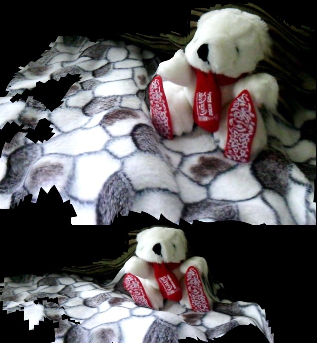
Link to github source code .
UPD: Updated version for windows, so if the previous version did not work for you, then this version will probably work. Plus added the ability to select the camera (if there are several).
Source: https://habr.com/ru/post/265713/
All Articles