Practice Mikrotik settings for dummies
UPD: 01/08/2018
There is a task: to configure the device based on RouterOS as a replacement for the SOHO router for a home or small office. This is a HOWTO, because there will be a minimum of technical details, Next-Next-Next-Ok and you get a device ready for operation, so let's get started.
Everything described has been tested on RouterBOARD RB 951G-2HnD, but can serve as an instruction for configuring any device based on RouterOS 6.25 and higher. To configure the device, you will need a proprietary winbox utility (for windows), or mactelnet-client (for linux), of course RouterOS has telnet / http / ssh, but for now let's forget about them.
We connect the PC to the fifth port of Mikrotik (in general, you can use any except the first one), turn the device over and see the mac address range on the sticker with the bar code, the latter refers to the fifth port, enter it into the winbox connection window, or use it as a mactelnet argument. User admin, password is missing.
')
A suggestion appears: save the base configuration, or reset the device. Select [Remove Configuration] . The device will reboot.

First of all, we create a new user and delete the admin, but everybody forgets about it.
Moving on: [System] ➙ [Users] ➙ [+] .
Name: login ;
Group: full (full access);
Password: password ;
Confirm Password: Password again .
Confirm by clicking on [Ok] .
In the table with users, select admin and press [] .


Disconnect and go to the device under the new user.
The provider will connect to the first port of RouterBOARD, the other four and the wireless interface are assigned to the home subnet 192.168.10.0/24, the router's address in the home subnet is 192.168.10.1, the network clients will receive addresses from the range 192.168.10.100-192.168.10.200.
There are various ways to connect to the provider, and if we have Ethernet at the physical level (even if it comes from an xDLS modem), then IPoE (Static or DHCP), PPPoE, L2TP, PPTP or a combination of them (generally PPTP, L2TP without configured IP will not work), in addition to everything, there may be a binding to the mac address. I will try to consider the most frequent cases.
But first, rename the ether1 interface to eth1-wan, for convenience: [Interfaces] ➙ [Ether1] ➙ [Name: eth1-wan] ➙ [OK] .

We connect the provider cable to the first port of the device.
Not to say that all providers use mac bindings, but they are quite common, especially if you use IPoE to bind IPs and protect against freeloaders.
Substitution can only be done through command mode, so click [New Terminal] and enter:
where 00: 11: 22: 33: 44: 55 - mac reserved by the provider.
The simplest option: [IP] ➙ [DHCP Client] ➙ [+] ➙ [Interface: eth1-wan] ➙ [OK] .

Also a simple option, but you will need to clarify the following parameters with the provider (the value is indicated as an example):
IP (ip address): 192.0.2.10;
mask: 255.255.255.0 (or / 24);
gateway: 192.0.2.1;
DNS1: 192.0.2.2;
DNS2: 192.0.2.3.
Add IP to the interface: [IP] ➙ [Addresses] ➙ [+] ➙ [Address: 192.0.2.10/255.255.255.0; Interface: eth1-wan] ➙ [OK] ;
Add default route: [IP] ➙ [Routes] ➙ [+] ➙ [Dst.Address: 0.0.0.0/0; Gateway: 192.0.2.1; Check gateway: ping; Distance: 1] ➙ [OK] ;
Add DNS: [IP] ➙ [DNS] ➙ [Servers: 192.0.2.2; 192.0.2.3] ➙ [OK] .


PPPoE is a tunnel protocol that does not require IP preconfiguration. Of course, the provider may have peering with other networks or access to its network without speed limits that work outside the PPPoE interface and require the addition of a separate route (DualAccess or Russian PPPoE in SOHO routers), but this configuration is beyond the scope of HOWTO for beginners.
To configure PPPoE, you will need to know the login and password to connect to the network (usually issued when entering into an agreement).
Add a tunnel interface: [PPP] ➙ [+] ➙ [PPPoE Client] .
On the [Genaral] tab, specify the interface name Name = tap1-wan and the interface interface Interface = eth1-wan .
On the [Dial Out] tab, we specify the login and password for the connection, the other options on the screenshots.


Important: If you are using PPPoE, then in the future, use the tap1-wan interface instead of eth1-wan.
Here we come to the richest pitfalls connection method. Both protocols are configured in a similar way, but they require IP pre-configuration (using DHCP or statically). The problem with mikrotik is that by specifying the address of the server with a domain name, it recognizes it into the address once and will only use this address, if the address changes (or the provider uses RoundRobin DNS and the server is overloaded), then it is likely to remain without the Internet. From the provider side, there can also be funny things, for example, DNS servers available only from the local network, or the need to pre-register a static route to the PPTP / L2TP server, if you are lucky enough to become a client of a yellow-striped provider, you can safely download and study the corresponding instructions . Option with DualAccess L2TP / PPTP is also possible.
But we will assume that everything is fine with you, you received the IP address by means of DHCP, check with your provider: login, password and vpn server, you can proceed to setup.
Add PPTP / L2TP interface: [PPP] ➙ [+] ➙ [PPTP Client or L2TP Client] .
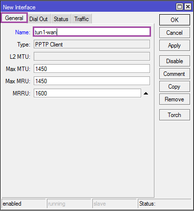
On the [General] tab, specify the name of the connection: Name = tun1-wan .
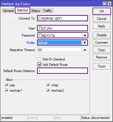
On the [Dial out] tab, we specify the PPTP or L2TP server, login and password.
Important: If you are using L2TP / PPTP, then later use tun1-wan interface instead of eth1-wan.
And just. If you get a USB modem, then most likely it will be defined as an ethernet interface in [Interfaces] ➙ [LTE] and it is enough to take IP from it using DHCP. But for the initial activation of the modem will have to connect to the PC. I don’t know with all the modem models that way or another I got caught up, but he refused to work on a PC without prior activation.
If the modem is not defined as a network card, but Mikrotik sees it in [System] ➙ [Resources] ➙ [USB] , then you will need to create a PPP connection for the usb1 interface, in some situations the device must first be switched to modem AT mode with a command (look at the corresponding forums). In any case, a great many options, one of them is described here .
At the moment, the ether2-ether5 and wlan1 interfaces work independently of each other, they need to be combined into a single data transmission medium.
Ethernet interfaces can be combined at the hardware level, which will increase the speed of data transmission and reduce the load on the CPU (compared to the software bridge). As the master port, ether5 will be used, you can assign any, but if another provider appears, then it will be logical to connect it to the second port (and disable the master port on it).
For RoS below 6.41:
Rename ether5 to eth5-lan: [Interfaces] ➙ [ether5] ➙ [Name: eth5-lan] ➙ [OK] ;
Rename ether2-ether4 and set master port for them: [Interfaces] ➙ [ether2-4] ➙ [Name: eth2-4-lan; Master Port = eth5-lan] ➙ [OK] .


An interesting moment. Means master port can combine the interfaces belonging to one chipset, on older models of chipsets can be several (switch column), the interfaces from different chipsets are combined through software Bridge, well, or patchcords.
Now all local Ethernet interfaces are combined under the name eth5-lan.
The wireless interface exists separately from Ethernet, for association it is required to resort to the program bridge (bridge).
Create a bridge interface: [Bridge] ➙ [+] ➙ [Name: br1-lan] ➙ [OK] ;
Add interfaces: [Bridge] ➙ [Ports] ➙ [+] ➙ [Interface: eth5-lan; Bridge: br1-lan] ➙ [OK]
[Bridge] ➙ [Ports] ➙ [+] ➙ [Interface: wlan1; Bridge: br1-lan] ➙ [OK]


For RoS 6.41 and up:
In the current version of RouterOS there is no master-port option anymore, now all settings are made inside the bridge interface
Create the br1-lan interface:
Add interfaces to the bridge:
Everything can be done through the GUI, the hw option is called hardware offload.
We draw attention to the hw option on wired interfaces, it is she who is now responsible for loading the switch (if possible). If you have several bridge interfaces and the hw option is enabled everywhere, then the device will independently choose which of the bridges to do with hardware, respectively, disable hw where it is least important independently.
Now all local Ethernet and wlan interfaces are united under the name br1-lan.
Thing dreary (or rather dreary to describe it), but necessary.
Add a security profile and specify the password for the wireless connection: [Wireless] ➙ [Security Profiles] ➙ [+]
Name - the name of the profile;
WPA / WPA2 Pre-Shared Key - keys for WPA / WPA2 (wi-fi password);
The rest of the screenshot, in the end [OK] .

Enable and configure the wireless interface: [Wireless] ➙ [wlan1] ➙ [Enable] .
On the [Wireless] tab:
Mode: ap bridge;
Band: 2gHz-b / g / n. If your wireless devices were released several years ago, then it is more logical to choose 2gHz-B / G. ;
Frequency: auto. In SOHO devices, this parameter is called Channel matching can be viewed by reference . If you are not sure what to choose, leave auto. ;
SSID: name of the access point;
Wireless Protocol: 802.11;
Securiity Profile: wpa2-protect. Profile created in the previous step .;
Bridge Mode: enabled;
Default Authenticate: yes;
Default Forward: yes;
Hide SSID: no. You can hide the access point. But do not consider this a panacea. ;
Next tab [Nstreme] .
Disable everything.
Once finished, click [Ok] and try to connect (the phone will not receive ip, but the connection should be established).


Add ip to the interface br1-lan: [IP] ➙ [Addresses] [+] ➙ [Address: 192.168.10.1/24; Interface: br1-lan] ➙ [OK]

Create an address pool for dhcp: [IP] ➙ [Pool] [+] ➙ [Name: dhcp-pc; Addresses: 192.168.10.100-192.168.10.200] ➙ [OK]

We enable wiretapping of dhcp requests on the br1-lan interface: [IP] ➙ [DHCP Server] ➙ [+] ➙ [Name: dhcp-pc; Interface: br1-lan; Lease Time: 08:00:00; Address Pool: dhcp-pc] ➙ [OK]

Now we need to decide which parameters will be given via dhcp: [IP] ➙ [DHCP Server] ➙ [Networks] ➙ [+]
Address: 192.168.10.0/24;
Gateway: 192.168.10.1;
Netmask: 24;
DNS Servers: 192.168.10.1.
At the end of [Ok] .

In the screenshot, the address of the router is specified as the NTP server, but Mikrotik does not know how to distribute the exact time in the base delivery, you can specify any other server from the network, or add and configure the ntp package (described at the end of the HOWTO).
If you are not satisfied with the DNS from the provider, you can add your own to the list (you can completely remove the provider DNS by turning off the Use peer DNS option in the corresponding connections).
Turn on DNS queries: [IP] ➙ [DNS] ➙ [Allow Remote Requests: yes] ➙ [OK]

Now the local network is working, restarting the network interface (or dhcp-client) to get ip from the router and can be used to connect via winbox / http / ssh / telnet / ftp / scp ip: 192.168.10.1.
A connection appeared between devices on the local network, when you try to ping any resource, its address is recognized, but Internet access is still missing. The time has come for the last major item: packet filter settings.
RouterOS is a type of GNU / Linux OS, netfilter is used as a packet filter, I can’t say the interface works directly with the kernel module or with iptables, but the developers have tried to make the syntax as close as possible to the latter.
In order not to describe each command separately, let's understand a little. The packet filter is configured in [IP] ➙ [Firewall] , we will be interested in tabs (tables in iptables terminology) [Filter] , [Nat] and [Mangle] . A number of rules can be added to each table (as elsewhere with the [+] button), the rules are processed alternately from top to bottom, so order is important. Each rule consists of Conditions separated into three tabs: General, Advanced, Extra and Actions, Action tab, there are statistics of the rule, but we are not interested in it. A rule can contain many conditions, the main thing is not to make them contradictory. If passing by the rules of the package fits all conditions, it is processed by the appropriate action and no longer goes ( in fact, some actions skip the package further, just remember this fact if you plan to deal with netfilter in the future ). In the variant for beginners, the conditions from the General tab will suffice.

What will be the settings? Users from the local network will have access to the Internet. Access to mikrotik from the local network will be limited to the services used (web, winbox, ssh, dns, ntp), from the external network access will be open via the web, but with the changed port address to 9999.
All the necessary rules are described in the form of tables, if you are afraid to make a mistake or just lazy, open [New terminal] and copy the lines from the console version at the end of the section into it.
Now the Internet should be available, if that’s enough for you, then close the HOWTO and use it if you want to learn more.
Give the device a name: [System] ➙ [Identity] ➙ [Name: MikRouter] ➙ [OK]
And we set it in dns: [IP] ➙ [DNS] ➙ [Static] ➙ [+] ➙ [Name: mikrouter; Address: 192.168.10.1] ➙ [OK]
Now the device can be accessed by the domain name mikrouter , but only from the local subnet.
Adjust the clock: [System] ➙ [Clock] ➙ [Time] ➙ [Time Zone Name: Time Zone ; Time: Current time ; Date: Current Date ] ➙ [OK]
We update the device and add packages.
Go to the site Mikrotik and download the archive with updates (Extra Packages) for your router. Unpack and leave the following (6.30.2 - the current version at the time of writing, updates are released quite often):
In Winbox, open [Files] and drag the selected packages using drag'n'drop (alternatively, you can download via the web interface or via ssh using scp).
To update, just restart the device: [System] ➙ [Reboot] ➙ [Yes]
Further, for updating it is not necessary to download packages: [System] ➙ [Packages] ➙ [Check for updates] ➙ [Channel: current] ➙ [Download & Install]
In previous additions, we set up the clock and added the NTP package, now it needs to be configured.
We enable ntp-client and set the server addresses (you can set your favorite ones) of the exact time: [System] ➙ [NTP Client] ➙ [Enabled: yes; Primary: 48.8.40.31; Secondary: 91.206.16.4] ➙ [OK]
Enable snooping ntp requests: [System] ➙ [NTP Server] ➙ [Enabled: yes] ➙ [OK]

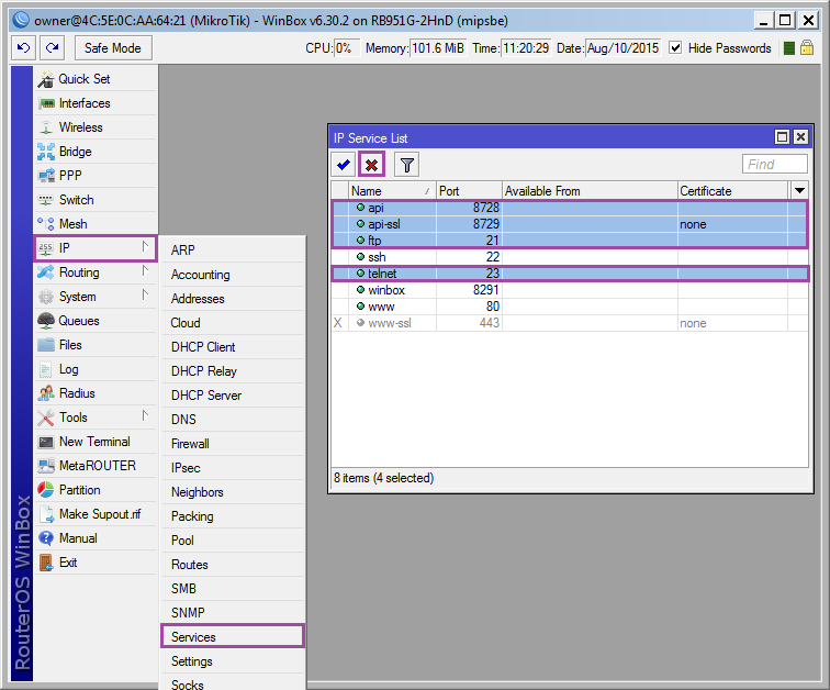
Leave the winbox / http / ssh, the rest can be enabled if necessary: [IP] ➙ [Services] select as in the screenshot and click [x] .
In winbox, there are means of detecting devices that are in the same physical network with a PC, this is convenient, but why should the neighbors know what device we have?
Disable: [IP] ➙ [Neighbor] ➙ [Discovery Interfaces] . You can leave the detection for br1-lan (local area network), you can remove your choice. For new interfaces, detection is enabled by default, do not forget about it.
Now we will restrict access to the mac-address (winbox and mactelnet): [Tools] ➙ [MAC Server] ➙ [Telnet Interfaces]
Disable ( [x] ) all and add br1-lan .
Go to [Winbox Interfaces] and repeat.
Many p2p applications and online games require UPnP (Dynamic Port Opening Service) for normal operation.
Enable: [IP] ➙ [UPnP] ➙ [Enabled: yes]
Adding interfaces: [Interfaces] ➙ [+]
External: eth1-wan;
Internal: br1-lan.
If the number of devices on the network has increased so much that the router has stopped coping, you can overclock the processor a bit: [System] ➙ [RouterBOARD] ➙ [Settings] ➙ [CPU Frequency: 750 MHz]
For RB 951G is the maximum frequency of the CPU.
Backup settings will never be over: [Files] ➙ [Backup]
Name: file name (without extension);
Password: password (if you do not specify the user password will be used);
Don't Encrypt: if there is no need to encrypt backup.
To restore, just copy the file to another device (preferably the same series and with the same version of RouterOS).
Go to [Files] ➙ [Restore] and select the file.
PS I have not raised a hand for 3 years to write something else, if there are interesting ideas for articles on RoS and Mikrotik, write in a personal.
There is a task: to configure the device based on RouterOS as a replacement for the SOHO router for a home or small office. This is a HOWTO, because there will be a minimum of technical details, Next-Next-Next-Ok and you get a device ready for operation, so let's get started.
Training
Everything described has been tested on RouterBOARD RB 951G-2HnD, but can serve as an instruction for configuring any device based on RouterOS 6.25 and higher. To configure the device, you will need a proprietary winbox utility (for windows), or mactelnet-client (for linux), of course RouterOS has telnet / http / ssh, but for now let's forget about them.
We connect the PC to the fifth port of Mikrotik (in general, you can use any except the first one), turn the device over and see the mac address range on the sticker with the bar code, the latter refers to the fifth port, enter it into the winbox connection window, or use it as a mactelnet argument. User admin, password is missing.
')
A suggestion appears: save the base configuration, or reset the device. Select [Remove Configuration] . The device will reboot.
Add user
First of all, we create a new user and delete the admin, but everybody forgets about it.
Moving on: [System] ➙ [Users] ➙ [+] .
Name: login ;
Group: full (full access);
Password: password ;
Confirm Password: Password again .
Confirm by clicking on [Ok] .
In the table with users, select admin and press [] .
Console version
/user add name= group=full password= /user remove admin Disconnect and go to the device under the new user.
Provider setting
The provider will connect to the first port of RouterBOARD, the other four and the wireless interface are assigned to the home subnet 192.168.10.0/24, the router's address in the home subnet is 192.168.10.1, the network clients will receive addresses from the range 192.168.10.100-192.168.10.200.
There are various ways to connect to the provider, and if we have Ethernet at the physical level (even if it comes from an xDLS modem), then IPoE (Static or DHCP), PPPoE, L2TP, PPTP or a combination of them (generally PPTP, L2TP without configured IP will not work), in addition to everything, there may be a binding to the mac address. I will try to consider the most frequent cases.
But first, rename the ether1 interface to eth1-wan, for convenience: [Interfaces] ➙ [Ether1] ➙ [Name: eth1-wan] ➙ [OK] .
Console option
/interface ethernet set [find default-name=ether1] name=eth1-wan We connect the provider cable to the first port of the device.
Mac address spoofing
Not to say that all providers use mac bindings, but they are quite common, especially if you use IPoE to bind IPs and protect against freeloaders.
Substitution can only be done through command mode, so click [New Terminal] and enter:
/interface ethernet set eth1-wan mac-address=00:11:22:33:44:55 where 00: 11: 22: 33: 44: 55 - mac reserved by the provider.
Automatically receive settings using DHCP.
The simplest option: [IP] ➙ [DHCP Client] ➙ [+] ➙ [Interface: eth1-wan] ➙ [OK] .
Console option
/ip dhcp-client add interface eth1-wan disabled=no Static IP Configuration
Also a simple option, but you will need to clarify the following parameters with the provider (the value is indicated as an example):
IP (ip address): 192.0.2.10;
mask: 255.255.255.0 (or / 24);
gateway: 192.0.2.1;
DNS1: 192.0.2.2;
DNS2: 192.0.2.3.
Add IP to the interface: [IP] ➙ [Addresses] ➙ [+] ➙ [Address: 192.0.2.10/255.255.255.0; Interface: eth1-wan] ➙ [OK] ;
Add default route: [IP] ➙ [Routes] ➙ [+] ➙ [Dst.Address: 0.0.0.0/0; Gateway: 192.0.2.1; Check gateway: ping; Distance: 1] ➙ [OK] ;
Add DNS: [IP] ➙ [DNS] ➙ [Servers: 192.0.2.2; 192.0.2.3] ➙ [OK] .
Console option
/ip address add address=192.0.2.10/255.255.255.0 interface=eth1-wan /ip route add dst-address=0.0.0.0/0 gateway=192.0.2.1 check-gateway=ping distance=1 /ip dns set servers=192.0.2.2,192.0.2.3 PPPoE setup
PPPoE is a tunnel protocol that does not require IP preconfiguration. Of course, the provider may have peering with other networks or access to its network without speed limits that work outside the PPPoE interface and require the addition of a separate route (DualAccess or Russian PPPoE in SOHO routers), but this configuration is beyond the scope of HOWTO for beginners.
To configure PPPoE, you will need to know the login and password to connect to the network (usually issued when entering into an agreement).
Add a tunnel interface: [PPP] ➙ [+] ➙ [PPPoE Client] .
On the [Genaral] tab, specify the interface name Name = tap1-wan and the interface interface Interface = eth1-wan .
On the [Dial Out] tab, we specify the login and password for the connection, the other options on the screenshots.
Console option
/interface pppoe-client add interface=eth1-wan name=tap1-wan disabled=no user= password= use-peer-dns=yes add-default-route=yes default-route-distance=0 Important: If you are using PPPoE, then in the future, use the tap1-wan interface instead of eth1-wan.
Configure L2TP / PPTP
Here we come to the richest pitfalls connection method. Both protocols are configured in a similar way, but they require IP pre-configuration (using DHCP or statically). The problem with mikrotik is that by specifying the address of the server with a domain name, it recognizes it into the address once and will only use this address, if the address changes (or the provider uses RoundRobin DNS and the server is overloaded), then it is likely to remain without the Internet. From the provider side, there can also be funny things, for example, DNS servers available only from the local network, or the need to pre-register a static route to the PPTP / L2TP server, if you are lucky enough to become a client of a yellow-striped provider, you can safely download and study the corresponding instructions . Option with DualAccess L2TP / PPTP is also possible.
But we will assume that everything is fine with you, you received the IP address by means of DHCP, check with your provider: login, password and vpn server, you can proceed to setup.
Add PPTP / L2TP interface: [PPP] ➙ [+] ➙ [PPTP Client or L2TP Client] .
On the [General] tab, specify the name of the connection: Name = tun1-wan .
On the [Dial out] tab, we specify the PPTP or L2TP server, login and password.
Console option
For l2tp, replace pptp-client with l2tp-client:
/interface pptp-client add name=tun1-wan disabled=no connect-to=_vpn user= password= add-default-route=yes default-route-distance=1 profile=default Important: If you are using L2TP / PPTP, then later use tun1-wan interface instead of eth1-wan.
But what about Yota?
And just. If you get a USB modem, then most likely it will be defined as an ethernet interface in [Interfaces] ➙ [LTE] and it is enough to take IP from it using DHCP. But for the initial activation of the modem will have to connect to the PC. I don’t know with all the modem models that way or another I got caught up, but he refused to work on a PC without prior activation.
Other 3G / 4G Modems
If the modem is not defined as a network card, but Mikrotik sees it in [System] ➙ [Resources] ➙ [USB] , then you will need to create a PPP connection for the usb1 interface, in some situations the device must first be switched to modem AT mode with a command (look at the corresponding forums). In any case, a great many options, one of them is described here .
LAN Interface Preparation
At the moment, the ether2-ether5 and wlan1 interfaces work independently of each other, they need to be combined into a single data transmission medium.
Ethernet interfaces can be combined at the hardware level, which will increase the speed of data transmission and reduce the load on the CPU (compared to the software bridge). As the master port, ether5 will be used, you can assign any, but if another provider appears, then it will be logical to connect it to the second port (and disable the master port on it).
For RoS below 6.41:
Rename ether5 to eth5-lan: [Interfaces] ➙ [ether5] ➙ [Name: eth5-lan] ➙ [OK] ;
Rename ether2-ether4 and set master port for them: [Interfaces] ➙ [ether2-4] ➙ [Name: eth2-4-lan; Master Port = eth5-lan] ➙ [OK] .
Console option
/interface ethernet set [find default-name=ether5] name=eth5-lan /interface ethernet set [find default-name=ether2] name=eth2-lan master-port=eth5-lan /interface ethernet set [find default-name=ether3] name=eth3-lan master-port=eth5-lan /interface ethernet set [find default-name=ether4] name=eth4-lan master-port=eth5-lan An interesting moment. Means master port can combine the interfaces belonging to one chipset, on older models of chipsets can be several (switch column), the interfaces from different chipsets are combined through software Bridge, well, or patchcords.
Now all local Ethernet interfaces are combined under the name eth5-lan.
The wireless interface exists separately from Ethernet, for association it is required to resort to the program bridge (bridge).
Create a bridge interface: [Bridge] ➙ [+] ➙ [Name: br1-lan] ➙ [OK] ;
Add interfaces: [Bridge] ➙ [Ports] ➙ [+] ➙ [Interface: eth5-lan; Bridge: br1-lan] ➙ [OK]
[Bridge] ➙ [Ports] ➙ [+] ➙ [Interface: wlan1; Bridge: br1-lan] ➙ [OK]
Console option
/interface bridge add name=br1-lan /interface bridge port add interface=eth5-lan bridge=br1-lan /interface bridge port add interface=wlan1 bridge=br1-lan For RoS 6.41 and up:
In the current version of RouterOS there is no master-port option anymore, now all settings are made inside the bridge interface
Create the br1-lan interface:
/interface bridge add name=br1-lan Add interfaces to the bridge:
/interface bridge port add bridge=br1-lan interface=eth2-lan hw=yes add bridge=br1-lan interface=eth3-lan hw=yes add bridge=br1-lan interface=eth4-lan hw=yes add bridge=br1-lan interface=eth5-lan hw=yes add bridge=br1-lan interface=wlan1 Everything can be done through the GUI, the hw option is called hardware offload.
We draw attention to the hw option on wired interfaces, it is she who is now responsible for loading the switch (if possible). If you have several bridge interfaces and the hw option is enabled everywhere, then the device will independently choose which of the bridges to do with hardware, respectively, disable hw where it is least important independently.
Now all local Ethernet and wlan interfaces are united under the name br1-lan.
Wireless security
Thing dreary (or rather dreary to describe it), but necessary.
Add a security profile and specify the password for the wireless connection: [Wireless] ➙ [Security Profiles] ➙ [+]
Name - the name of the profile;
WPA / WPA2 Pre-Shared Key - keys for WPA / WPA2 (wi-fi password);
The rest of the screenshot, in the end [OK] .
Console option
/interface wireless security-profiles add name=wpa2-protected mode=dynamic-keys authentication-types=wpa-psk,wpa2-psk unicast-chiphers=aes-ccm group-chiphers=aes-ccm wpa-pre-shared-key=_wpa wpa2-pre-shared-key=_wpa2 Enable and configure the wireless interface: [Wireless] ➙ [wlan1] ➙ [Enable] .
On the [Wireless] tab:
Mode: ap bridge;
Band: 2gHz-b / g / n. If your wireless devices were released several years ago, then it is more logical to choose 2gHz-B / G. ;
Frequency: auto. In SOHO devices, this parameter is called Channel matching can be viewed by reference . If you are not sure what to choose, leave auto. ;
SSID: name of the access point;
Wireless Protocol: 802.11;
Securiity Profile: wpa2-protect. Profile created in the previous step .;
Bridge Mode: enabled;
Default Authenticate: yes;
Default Forward: yes;
Hide SSID: no. You can hide the access point. But do not consider this a panacea. ;
Next tab [Nstreme] .
Disable everything.
Once finished, click [Ok] and try to connect (the phone will not receive ip, but the connection should be established).
Console option
/interface wireless set wlan1 disabled=no ssid=MyRouter mode=ap-bridge band=2ghz-b/g/n frequency=2412 bridge-mode=enabled wireless-protocol=802.11 security-profile=wpa2-protect default-authentication=yes default-forwarding=yes hide-ssid=no /interface wireless nstreme set wlan1 enable-nstreme=no enable-polling=no disable-csma=no Setting ip, dhcp-server
Add ip to the interface br1-lan: [IP] ➙ [Addresses] [+] ➙ [Address: 192.168.10.1/24; Interface: br1-lan] ➙ [OK]
Console option
/ip address add address=192.168.10.1/24 interface=br1-lan Create an address pool for dhcp: [IP] ➙ [Pool] [+] ➙ [Name: dhcp-pc; Addresses: 192.168.10.100-192.168.10.200] ➙ [OK]
Console option
/ip pool add name=dhcp-pc address=192.168.10.100-192.168.10.200 We enable wiretapping of dhcp requests on the br1-lan interface: [IP] ➙ [DHCP Server] ➙ [+] ➙ [Name: dhcp-pc; Interface: br1-lan; Lease Time: 08:00:00; Address Pool: dhcp-pc] ➙ [OK]
Now we need to decide which parameters will be given via dhcp: [IP] ➙ [DHCP Server] ➙ [Networks] ➙ [+]
Address: 192.168.10.0/24;
Gateway: 192.168.10.1;
Netmask: 24;
DNS Servers: 192.168.10.1.
At the end of [Ok] .
In the screenshot, the address of the router is specified as the NTP server, but Mikrotik does not know how to distribute the exact time in the base delivery, you can specify any other server from the network, or add and configure the ntp package (described at the end of the HOWTO).
Console option
/ip dhcp-server add name=dhcp-pc interface=br1-lan lease-time=08:00:00 address-pool=dhcp-pc /ip dhcp-server network add address=192.168.10.0/24 dns-server=192.168.10.1 gateway=192.168.10.1 netmask=24 Domain Name Server Setup
If you are not satisfied with the DNS from the provider, you can add your own to the list (you can completely remove the provider DNS by turning off the Use peer DNS option in the corresponding connections).
Turn on DNS queries: [IP] ➙ [DNS] ➙ [Allow Remote Requests: yes] ➙ [OK]
Console option
/ip dns set allow-remote-requests=yes Now the local network is working, restarting the network interface (or dhcp-client) to get ip from the router and can be used to connect via winbox / http / ssh / telnet / ftp / scp ip: 192.168.10.1.
A connection appeared between devices on the local network, when you try to ping any resource, its address is recognized, but Internet access is still missing. The time has come for the last major item: packet filter settings.
Packet filter
RouterOS is a type of GNU / Linux OS, netfilter is used as a packet filter, I can’t say the interface works directly with the kernel module or with iptables, but the developers have tried to make the syntax as close as possible to the latter.
In order not to describe each command separately, let's understand a little. The packet filter is configured in [IP] ➙ [Firewall] , we will be interested in tabs (tables in iptables terminology) [Filter] , [Nat] and [Mangle] . A number of rules can be added to each table (as elsewhere with the [+] button), the rules are processed alternately from top to bottom, so order is important. Each rule consists of Conditions separated into three tabs: General, Advanced, Extra and Actions, Action tab, there are statistics of the rule, but we are not interested in it. A rule can contain many conditions, the main thing is not to make them contradictory. If passing by the rules of the package fits all conditions, it is processed by the appropriate action and no longer goes ( in fact, some actions skip the package further, just remember this fact if you plan to deal with netfilter in the future ). In the variant for beginners, the conditions from the General tab will suffice.
What will be the settings? Users from the local network will have access to the Internet. Access to mikrotik from the local network will be limited to the services used (web, winbox, ssh, dns, ntp), from the external network access will be open via the web, but with the changed port address to 9999.
All the necessary rules are described in the form of tables, if you are afraid to make a mistake or just lazy, open [New terminal] and copy the lines from the console version at the end of the section into it.
[Filter] tab
| Conditions | Act | |||||||||
|---|---|---|---|---|---|---|---|---|---|---|
| # | Chain | Src. Address | Dst. Address | Protocol | Dst.Port | In. Interface | Out. Interface | Connection mark | Connection state | |
| 0 | Input | icmp | accept | |||||||
| one | Input | 192.168.10.0/24 | tcp | 80,8291,22 | br1-lan | new | accept | |||
2 | Input | tcp | 80 | eth1-wan | allow_in | new | accept | |||
| 3 | Input | 192.168.10.0/24 | udp | 53,123 | br1-lan | new | accept | |||
| four | Input | established, related | accept | |||||||
| five | Output | [!] Invalid | accept | |||||||
| 6 | Forward | 192.168.10.0/24 | br1-lan | eth1-wan | new, established | accept | ||||
| 7 | Forward | 192.168.10.0/24 | eth1-wan | br1-lan | established, related | accept | ||||
| eight | Input | reject | ||||||||
| 9 | Output | reject | ||||||||
| ten | Forward | reject | ||||||||
[NAT] tab
| Conditions | Act | ||||||
|---|---|---|---|---|---|---|---|
| # | Chain | Src. Address | Protocol | Dst.Port | In. Interface | Out. Interface | |
| 0 | srcnat | 192.168.10.0/24 | eth1-wan | masquerade | |||
one | dstnat | tcp | 9999 | eth1-wan | redirect | ||
[Mangle] tab
| Conditions | Act | |||||
|---|---|---|---|---|---|---|
| # | Chain | Protocol | Dst.Port | In. Interface | Connection state | |
0 | prerouting | tcp | 9999 | eth1-wan | new | mark connection |
Console option
/ip firewall filter add chain=input protocol=icmp add chain=input connection-state=new dst-port=80,8291,22 in-interface=br1-lan protocol=tcp src-address=192.168.10.0/24 add chain=input connection-mark=allow_in connection-state=new dst-port=80 in-interface=eth1-wan protocol=tcp add chain=input connection-state=new dst-port=53,123 protocol=udp src-address=192.168.10.0/24 add chain=input connection-state=established,related add chain=output connection-state=!invalid add chain=forward connection-state=established,new in-interface=br1-lan out-interface=eth1-wan src-address=192.168.10.0/24 add chain=forward connection-state=established,related in-interface=eth1-wan out-interface=br1-lan add action=drop chain=input add action=drop chain=output add action=drop chain=forward /ip firewall nat add action=masquerade chain=srcnat out-interface=eth1-wan src-address=192.168.10.0/24 add action=redirect chain=dstnat dst-port=9999 protocol=tcp to-ports=80 /ip firewall mangle add action=mark-connection chain=prerouting dst-port=9999 new-connection-mark=allow_in protocol=tcp connection-state=new Now the Internet should be available, if that’s enough for you, then close the HOWTO and use it if you want to learn more.
Addition 1. Device name
Give the device a name: [System] ➙ [Identity] ➙ [Name: MikRouter] ➙ [OK]
And we set it in dns: [IP] ➙ [DNS] ➙ [Static] ➙ [+] ➙ [Name: mikrouter; Address: 192.168.10.1] ➙ [OK]
Now the device can be accessed by the domain name mikrouter , but only from the local subnet.
Console option
/system identity set name=MikRouter /ip dns static add name=mikrouter address=192.168.12.10 Addition 2. Time setting
Adjust the clock: [System] ➙ [Clock] ➙ [Time] ➙ [Time Zone Name: Time Zone ; Time: Current time ; Date: Current Date ] ➙ [OK]
Addition 3. Update
We update the device and add packages.
Go to the site Mikrotik and download the archive with updates (Extra Packages) for your router. Unpack and leave the following (6.30.2 - the current version at the time of writing, updates are released quite often):
advanced-tools-6.30.2-mipsbe.npk dhcp-6.30.2-mipsbe.npk multicast-6.30.2-mipsbe.npk ntp-6.30.2-mipsbe.npk ppp-6.30.2-mipsbe.npk routing-6.30.2-mipsbe.npk security-6.30.2-mipsbe.npk system-6.30.2-mipsbe.npk user-manager-6.30.2-mipsbe.npk wireless-6.30.2-mipsbe.npk In Winbox, open [Files] and drag the selected packages using drag'n'drop (alternatively, you can download via the web interface or via ssh using scp).
To update, just restart the device: [System] ➙ [Reboot] ➙ [Yes]
Console reboot option
/system reboot Further, for updating it is not necessary to download packages: [System] ➙ [Packages] ➙ [Check for updates] ➙ [Channel: current] ➙ [Download & Install]
Console option
/system package update download /system package update install Appendix 4. Configuring ntp
In previous additions, we set up the clock and added the NTP package, now it needs to be configured.
We enable ntp-client and set the server addresses (you can set your favorite ones) of the exact time: [System] ➙ [NTP Client] ➙ [Enabled: yes; Primary: 48.8.40.31; Secondary: 91.206.16.4] ➙ [OK]
Enable snooping ntp requests: [System] ➙ [NTP Server] ➙ [Enabled: yes] ➙ [OK]
Console option
/system ntp client set enabled=yes primaty-ntp=48.8.40.31 secondary-ntp=91.206.16.4 /system ntp server set enabled=yes Addition 5. Disable extra services
Leave the winbox / http / ssh, the rest can be enabled if necessary: [IP] ➙ [Services] select as in the screenshot and click [x] .
Console option
/ip service set telnet disabled=yes set ftp disabled=yes set api disabled=yes set api-ssl disabled=yes set https disabled=yes set www-ssl disabled=no set winbox disabled=no set www disabled=no Addition 6. Disable detection and limit access to mactelnet
In winbox, there are means of detecting devices that are in the same physical network with a PC, this is convenient, but why should the neighbors know what device we have?
Disable: [IP] ➙ [Neighbor] ➙ [Discovery Interfaces] . You can leave the detection for br1-lan (local area network), you can remove your choice. For new interfaces, detection is enabled by default, do not forget about it.
Console option
/ip neighbor discovery :foreach i in=[find] do={ set $i discovery=no } Now we will restrict access to the mac-address (winbox and mactelnet): [Tools] ➙ [MAC Server] ➙ [Telnet Interfaces]
Disable ( [x] ) all and add br1-lan .
Go to [Winbox Interfaces] and repeat.
Console option
/tool mac-server set [ find default=yes ] disabled=yes add interface=br1-lan /tool mac-server mac-winbox set [ find default=yes ] disabled=yes add interface=br1-lan Addition 7. We include UPnP
Many p2p applications and online games require UPnP (Dynamic Port Opening Service) for normal operation.
Enable: [IP] ➙ [UPnP] ➙ [Enabled: yes]
Adding interfaces: [Interfaces] ➙ [+]
External: eth1-wan;
Internal: br1-lan.
Console option
/ip upnp set enabled=yes /ip upnp interfaces add interface=eth1-wan type=external add interface=br1-lan type=internal Addition 8. Overclocking
If the number of devices on the network has increased so much that the router has stopped coping, you can overclock the processor a bit: [System] ➙ [RouterBOARD] ➙ [Settings] ➙ [CPU Frequency: 750 MHz]
For RB 951G is the maximum frequency of the CPU.
Console option
/system routerboard settings set cpu-frequency=750MHz Supplement 9. Backup settings
Backup settings will never be over: [Files] ➙ [Backup]
Name: file name (without extension);
Password: password (if you do not specify the user password will be used);
Don't Encrypt: if there is no need to encrypt backup.
Console option
/system backup save name=router6.30.2 dont-encrypt=yes To restore, just copy the file to another device (preferably the same series and with the same version of RouterOS).
Go to [Files] ➙ [Restore] and select the file.
Console option
/system backup load name=router6.30.2.backup PS I have not raised a hand for 3 years to write something else, if there are interesting ideas for articles on RoS and Mikrotik, write in a personal.
Source: https://habr.com/ru/post/265387/
All Articles