Local network organization with simultaneous connection to two Internet providers using MikroTik router
Suppose we have two ISPs. The first one receives the settings via L2TP, for the second one it is necessary to set the settings statically, and we need to organize a trouble-free Internet connection. That is, in case of failure of the first Internet provider, the router should automatically switch to the second (backup) provider. And when the connection with the first provider is restored, the router should start working with it again.

To solve the problem, we will use a router configured on the basis of RouterOS. In this example, MikroTik rb951ui (5-port). Provider “1” (ISP1) via L2TP will be connected to port No. 1 accordingly. In the second port provider "2" (ISP2) with StaticIP. Ports №3, №4, №5 will serve to connect network clients. IP addresses on the local network will be distributed via DHCP. The availability of the first or second channel will be judged by the availability of the IP address. For example, take DNS google.com, the probability of failure of which is very small.
Sequencing. We connect the router to port number 3 and, accordingly, the LAN interface of the PC. To configure RouterOS, the winbox utility will be used. Go to the MAC-address and log in. We see the router configuration interface. (Fig. 1)
')
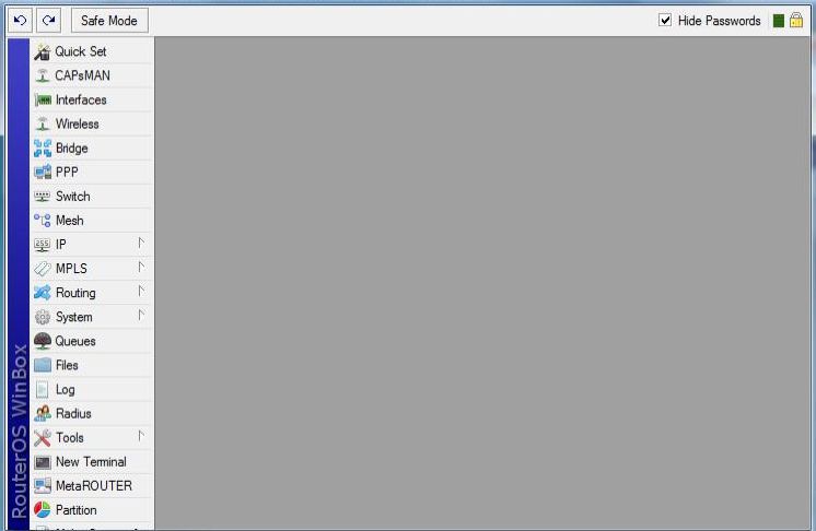
Fig. 1. RouterOS configuration interface
The first thing we do is configure the interfaces of provider “1” and provider “2” Fig.2, as well as configure the LAN for ports 3, 4 and 5.
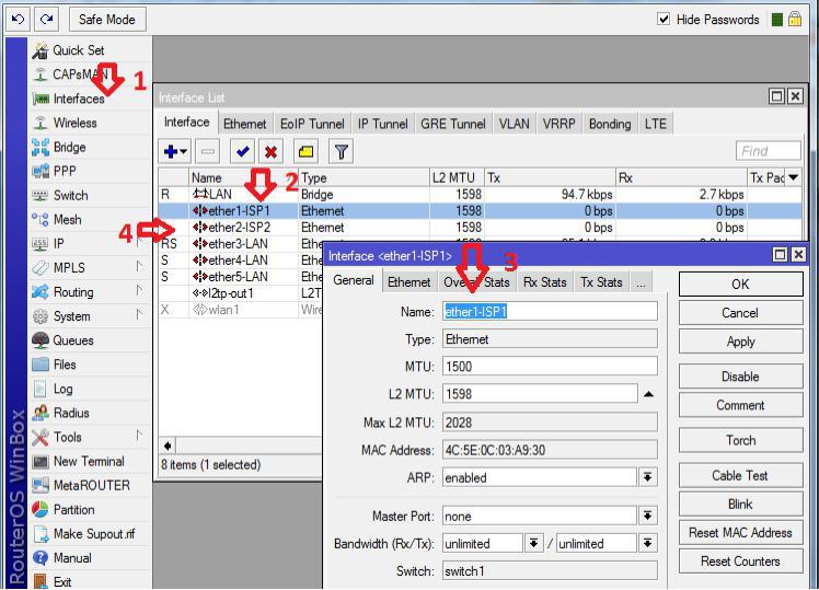
Fig. 2. Setting up provider "1" and provider "2"
In this case, Interface-1 belongs to provider “1” (ISP1 is a name for convenience) Interface-2 belongs to provider “2” (ISP2). For LAN organization, go to the “Bridge” menu item and add an interface with the name LAN. (Fig.3).
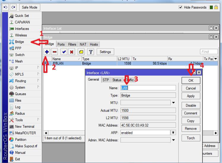
Fig. 3. Organization of LAN
Indicates the ports that will belong to the internal network (Figure 4)
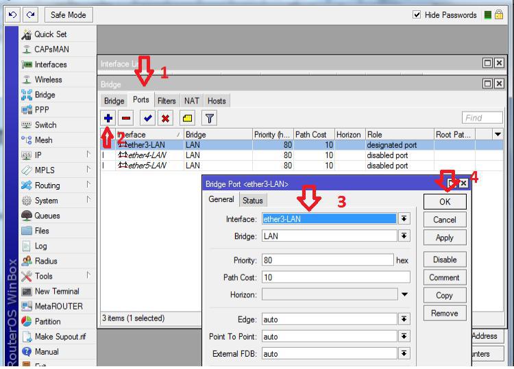
Fig. 4. Adding Ports to LAN
Now you need to add the IP addresses of the providers, as well as specify the IP address of the gateway to our local network (Fig. 5).
Description: The first thing we do is add a local area network gateway (numbers 4, 5). Interface we specify LAN. Second, add the static address of the second provider (numbers 6, 7)
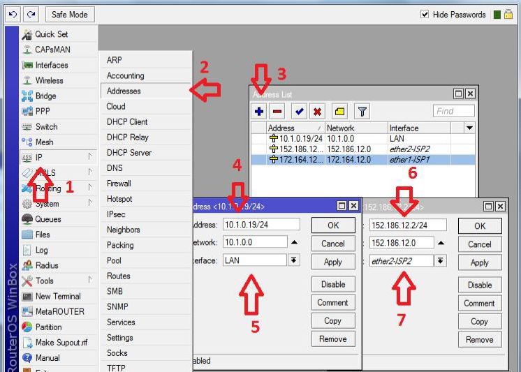
Fig. 5. Adding Addresses for Interfaces
Since the organization of the connection with the first provider is carried out via L2TP, it is necessary to add an L2TP client (Fig. 6)
Note: Add L2TP-client (Number 2). We indicate the corresponding parameters in the Dial-out tab, namely the server address, login and password, which are issued by the first provider (numbers 4, 5 and 6).
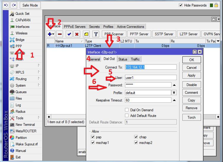
Fig. 6. Adding an L2TP Client
After adding a client in the status tab, we get a connection. (Fig. 7)
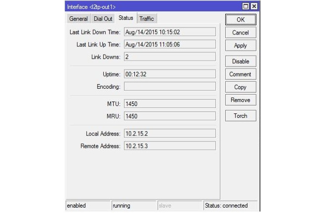
Fig. 7. Status of L2TP Connection
Now we are going to organize a DHCP server to distribute addresses to our internal network clients. The first thing we will do is create a pool of issued addresses (Figure 8), and then configure the DHCP server itself. (Figure 9).

Fig. 8. Creating a pool of issued addresses

Fig. 9. Adding and configuring a DHCP server
Description of the DHCP server: Add the server with the name (server1) to the internal LAN interface with the address pool that was created earlier. In the network we specify which parameters to transfer to the server to the clients.
Now we need to add static routes, since all interaction between networks is carried out in accordance with the routing table. It is controlled in RouterOS in the “Routes” menu. Addressing with a local network and with internal networks of providers was added dynamically. It remains to add routes to the Internet (to the address 0.0.0.0/0) through provider gateways. (Fig. 10).
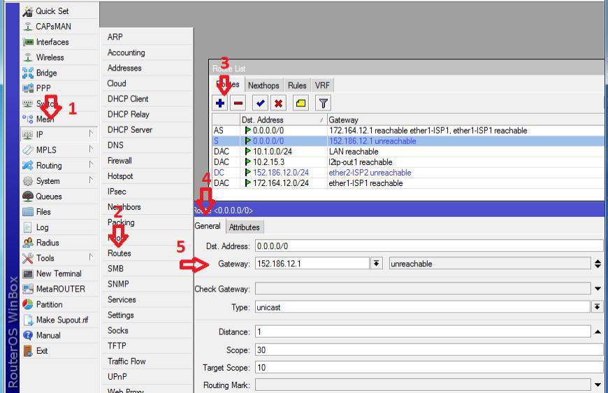
Fig. 10. Adding static routes
Further, it is necessary to organize switching of channels in case of unavailability of 1 channel. The router's OS has a built-in utility “Netwatch”, which allows you to monitor the status of hosts on your network by sending ICMP requests (ping) and perform any actions based on their availability. We will track the IP address 8.8.4.4 through the first channel, and if it is not available, switch routes to work on the second one.
We create a new “Netwatch host”, in the “Host” column we indicate the monitored IP address, and in “Interval” we indicate the frequency of the checks being made. (Fig. 11).
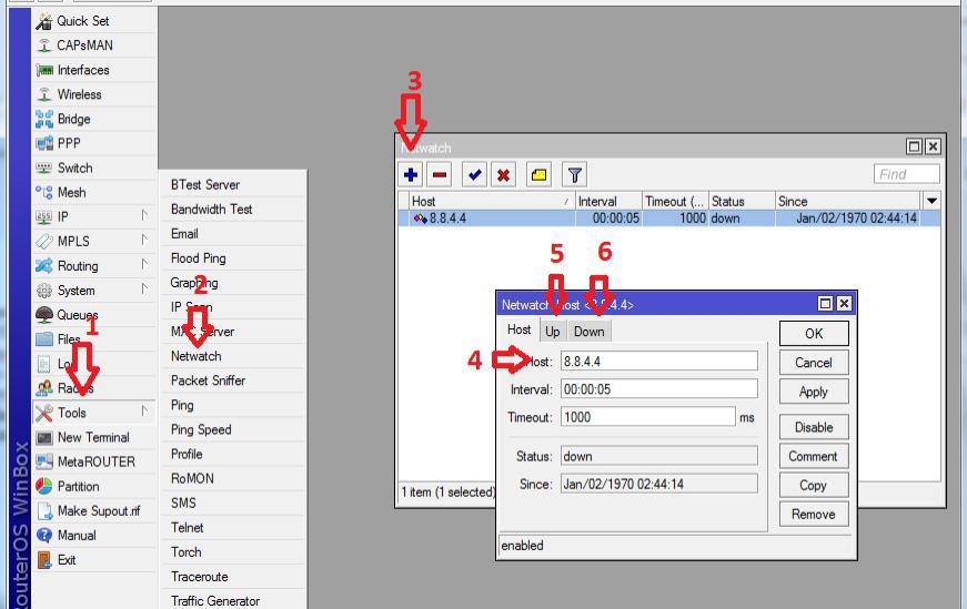
Fig. 11. Configure channel switching
And finally, in the Up tab (number 5) you need to write the following rule:
# turn on the route with the comment "ISP1" (main channel)
/ ip route set [find comment = "ISP1"] disabled = no
# disable the route with the comment "ISP2" (backup channel)
/ ip route set [find comment = "ISP2"] disabled = yes
In the Down tab, write the following rule:
# disable the route with the comment "ISP1" (backup channel)
/ ip route set [find comment = "ISP1"] disabled = yes
# we include the route with the comment "ISP2" (main channel)
/ ip route set [find comment = "ISP2"] disabled = no
Setting rules for passing traffic
Using the built-in firewall, you can control absolutely all traffic; we need to disable ping on ISP2. To do this in the terminal window we will write the following:
# approve use of icmp protocol
ip firewall filter add chain = input comment = "Permit icmp"
# limit ping 8.8.4.4 via ISP2
ip firewall filter add action = drop chain = output comment = "Deny 8.8.4.4 to reserved internet-channel" dst-address = 8.8.4.4 out-interface = "ether2 - internet II (reserve)" protocol = "icmp"
The material is introductory and intended to familiarize with the issue of managing a network with two providers.
To solve the problem, we will use a router configured on the basis of RouterOS. In this example, MikroTik rb951ui (5-port). Provider “1” (ISP1) via L2TP will be connected to port No. 1 accordingly. In the second port provider "2" (ISP2) with StaticIP. Ports №3, №4, №5 will serve to connect network clients. IP addresses on the local network will be distributed via DHCP. The availability of the first or second channel will be judged by the availability of the IP address. For example, take DNS google.com, the probability of failure of which is very small.
Sequencing. We connect the router to port number 3 and, accordingly, the LAN interface of the PC. To configure RouterOS, the winbox utility will be used. Go to the MAC-address and log in. We see the router configuration interface. (Fig. 1)
')
Fig. 1. RouterOS configuration interface
The first thing we do is configure the interfaces of provider “1” and provider “2” Fig.2, as well as configure the LAN for ports 3, 4 and 5.
Fig. 2. Setting up provider "1" and provider "2"
In this case, Interface-1 belongs to provider “1” (ISP1 is a name for convenience) Interface-2 belongs to provider “2” (ISP2). For LAN organization, go to the “Bridge” menu item and add an interface with the name LAN. (Fig.3).
Fig. 3. Organization of LAN
Indicates the ports that will belong to the internal network (Figure 4)
Fig. 4. Adding Ports to LAN
Now you need to add the IP addresses of the providers, as well as specify the IP address of the gateway to our local network (Fig. 5).
Description: The first thing we do is add a local area network gateway (numbers 4, 5). Interface we specify LAN. Second, add the static address of the second provider (numbers 6, 7)
Fig. 5. Adding Addresses for Interfaces
Since the organization of the connection with the first provider is carried out via L2TP, it is necessary to add an L2TP client (Fig. 6)
Note: Add L2TP-client (Number 2). We indicate the corresponding parameters in the Dial-out tab, namely the server address, login and password, which are issued by the first provider (numbers 4, 5 and 6).
Fig. 6. Adding an L2TP Client
After adding a client in the status tab, we get a connection. (Fig. 7)
Fig. 7. Status of L2TP Connection
Now we are going to organize a DHCP server to distribute addresses to our internal network clients. The first thing we will do is create a pool of issued addresses (Figure 8), and then configure the DHCP server itself. (Figure 9).
Fig. 8. Creating a pool of issued addresses
Fig. 9. Adding and configuring a DHCP server
Description of the DHCP server: Add the server with the name (server1) to the internal LAN interface with the address pool that was created earlier. In the network we specify which parameters to transfer to the server to the clients.
Now we need to add static routes, since all interaction between networks is carried out in accordance with the routing table. It is controlled in RouterOS in the “Routes” menu. Addressing with a local network and with internal networks of providers was added dynamically. It remains to add routes to the Internet (to the address 0.0.0.0/0) through provider gateways. (Fig. 10).
Fig. 10. Adding static routes
Further, it is necessary to organize switching of channels in case of unavailability of 1 channel. The router's OS has a built-in utility “Netwatch”, which allows you to monitor the status of hosts on your network by sending ICMP requests (ping) and perform any actions based on their availability. We will track the IP address 8.8.4.4 through the first channel, and if it is not available, switch routes to work on the second one.
We create a new “Netwatch host”, in the “Host” column we indicate the monitored IP address, and in “Interval” we indicate the frequency of the checks being made. (Fig. 11).
Fig. 11. Configure channel switching
And finally, in the Up tab (number 5) you need to write the following rule:
# turn on the route with the comment "ISP1" (main channel)
/ ip route set [find comment = "ISP1"] disabled = no
# disable the route with the comment "ISP2" (backup channel)
/ ip route set [find comment = "ISP2"] disabled = yes
In the Down tab, write the following rule:
# disable the route with the comment "ISP1" (backup channel)
/ ip route set [find comment = "ISP1"] disabled = yes
# we include the route with the comment "ISP2" (main channel)
/ ip route set [find comment = "ISP2"] disabled = no
Setting rules for passing traffic
Using the built-in firewall, you can control absolutely all traffic; we need to disable ping on ISP2. To do this in the terminal window we will write the following:
# approve use of icmp protocol
ip firewall filter add chain = input comment = "Permit icmp"
# limit ping 8.8.4.4 via ISP2
ip firewall filter add action = drop chain = output comment = "Deny 8.8.4.4 to reserved internet-channel" dst-address = 8.8.4.4 out-interface = "ether2 - internet II (reserve)" protocol = "icmp"
The material is introductory and intended to familiarize with the issue of managing a network with two providers.
Source: https://habr.com/ru/post/265225/
All Articles