Mobile printing

In our time, no one will be surprised by printing pictures on a sheet of paper. There is a huge selection of printers (including pocket). Many of my friends are buying or collecting 3D printers. I want to tell you how I reinvent the wheel. So, again, a step back is a story about 2D printing. A story about how I made a mobile printer for a phone based on a thermal printer (a printer that prints on thermal paper — no ink is needed, only special paper and electricity), a bluetooth module, and a few other little things.
I want to immediately warn you that in electronics and electrical engineering I don’t understand anything, that I basically did not use ready-made solutions and libraries. Therefore, this is a story about the handle and bicycles, about the problems I encountered. Continue reading at your own risk.
Super technology device
I think I don’t need to be reminded that we live in the age of mobile technology. I remember how about 20 years ago I thought that there would be a little more and the world would be full of robots, flying cars and many, many more amazing things. Taking into account the fact that I thought that some more and everyone will have their own robots, it’s also symbolic that we really don’t have any robots (I’m sorry for the vacuum cleaner advocates, please forgive me the last sentence), but there’s something else ... I believed if I was then told that almost every person on earth would have a supertechnological device in his pocket, with which people would sit on the toilet, run a simulation of the physical interactions of the process of stuffing birds in pigs. And if they told me that this device would be called a telephone, I would have laughed at all in the face of the narrator.
A bit of history
The 95th year was on the nose (maybe earlier, but I already wrote in the last paragraph about “20 years ago”, and “20” is a beautiful and round number, so I will stay with him) and one of my acquaintances from the yard had Gameboy (DMG-001). I don’t think it’s worth telling how cool he was by the standards of the time and what queue lined up to watch and hold this miracle of technology in hand. In the early 2000s, this device again reminded of itself, because additional peripherals appeared to him, namely the camera and the printer. There was no real need for such a camera or printer (even more so of such quality), but the very idea of a mobile device from which it was possible to print a small picture seemed a step into the future.
')

Back to topic
So, 20 years have passed and I thought that it would be possible to make a similar device, only for a super-technological device - a telephone.
The idea was quite simple and was based on the following things:
- Thermal Printer (A2 Micro Panel Thermal Printer).
- Bluetooth module (JY-MCU BT_BOARD V1.06).
- Controller (Stellaris Launchpad LM4F120XL. To avoid the “why?” Questions, I will immediately reply that I just had this particular board at hand).
- Screen (LCD 84x48 Nokia 5110) and several led diodes for status indication.
- Battery and regulator (Turnigy UBEC 5A).
- Application for Android to manage the printer (read as "print").
- Discharge on the handle and poor knowledge of the fundamentals of electrical engineering.
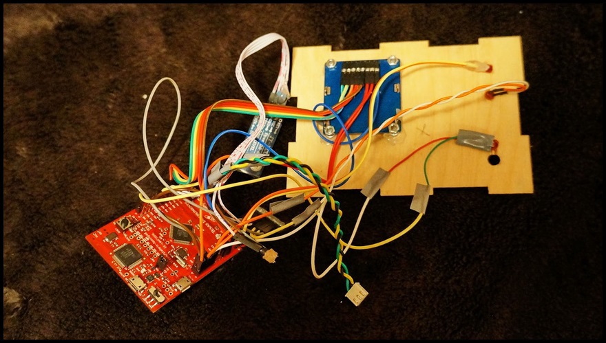
It is because of the 7th point that I have to ask for forgiveness from everyone who is upset by my implementation. Forgive me, but you will not find an adequate development of devices in this narration for making printed circuit boards, debugging a device using an oscilloscope and other goodies. I don't have the necessary tools either, because in everyday life, I don’t work in this area, and I don’t want to lose my job in handcuffing. I tried to improve my knowledge of the subject area a little, but somehow, I understand that I can be mistaken in terminology. I myself find it painful to look at the code of people far from programming, therefore, in order not to take more time from lovers of the beautiful in the field of electrical engineering, I post a photo of how everything was collected:
Well, for everyone who continued reading after the last photo, the achiveka “Experienced the hell of the perfectionist electrical engineer” is available ...

So, as I said, the idea was simple: there is a picture on the phone (it doesn't matter what the source of the picture is, just accept that there is a picture), you need to reduce it, manipulate brightness and contrast (if necessary), then dither (dither) to get a black and white image, then send via bluetooth to the printer and directly print.
Since I am developing software, there were no problems or problems with the software. A simple protocol of data exchange between the printer and the control device was implemented (since the printer accepts commands via bluetooth, it makes no sense to be limited to just the phone):
- Binary protocol is used to deceive data.
- Data is transmitted in the form of packets, each of which begins with a header (what a packet, how much data).
- There are two replies for each request packet (“request received” and “request execution complete”). It would have been possible to do with one answer, but in this mode it was possible to better control the state of the printer — there is no need to implement a command queue on the controller side, since the controller itself reports that it is ready to execute a new request.
In addition to service commands such as “is the printer alive?”, Only a few commands were implemented that are directly related to printing (image printing and paper feed).
Since the printer is capable of printing only monochrome images, a simplified Bitmap analogue with 1bpp (1 bit per pixel) was chosen as the image format. The printer is capable of printing 384 dots per line, which means that 48 bytes are needed to print one full line (not counting the header).
Communication problems
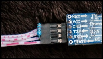
I will not focus on the fact that the controller refused to receive data from the bluetooth module due to too low voltage on the leg of the TX module, since I spent a lot of time debugging this part. I killed about two days for this, because first I checked everything I could and only then went to read the Internet, from where I found out that this is a feature of the selected module and that I would have to tighten the level to the required 3.3V myself, or I would have to force the module and solder the diode from it (which I decided not to do).
After I was able to receive packets on the controller side, another problem appeared: the data came in part. Until now, I can’t say exactly what the problem was, but here the toli is the buffer limit of the bluetooth module, toli is its data transfer / processing speed. The problem was this: we send a packet (for example, kilobytes of data), on the controller side we get 990-1023 bytes with losses in a random range (random data area, random number). Data loss occurred in about 50% of cases and was always a small percentage of the original data (no more than 50 bytes, even when sending a few kilobytes). The problem was repeated at all data exchange rates (not that I checked everything, but checked both the mean and the boundaries - 1200 and 115200 baud), but disappeared when adding the delay between sending data. In order not to embed synthetic delays, I decided that I would simply supplement the data exchange protocol:
- A checksum of the packet has been added.
- Data within the packet was transmitted by fragments, after the transmission of a fragment of data, a response was expected from the controller, which sent the sequence number of the received fragment.
- A service pack was added to set the fragment size (usually 128 bytes are used, but I left the ability to change the size of the fragment).
So, the first thing that was needed to determine the beginning of a packet is the signature (a certain sequence of bytes):
inline bool _receiveSignature( ) { unsigned char character; unsigned int offset = 0; while( offset != SIGNATURE_SIZE ) { if( _readByte( &character ) ) { if( character != SIGNATURE[offset] ) { if( character == SIGNATURE[0] ) offset = 1; else offset = 0; } else offset++; } else return false; } return true; } The idea with the signature is not new. In the event that one of the parties, for some reason, interrupted reception of the packet in the middle of the transmission, the remaining packet data should not be interpreted as the next packet. Thus, reception begins with the fact that all bytes are removed (ignored) from the buffer, before the signature - the beginning of the packet header. Thus, it is ensured that random garbage in the buffer (remnants of the past packet) will not be considered the header of the new packet.
The code for receiving data by fragments (data area, after receiving and checking the header):
unsigned char *buffer = m_buffer; unsigned int size = m_header.size; _sendCallback( 0 ); // resets fragment id while( size > 0 ) { unsigned int fragmentSize = _min( size, m_fragmentSize ); if( read( buffer, fragmentSize ) ) { size -= fragmentSize; buffer += fragmentSize; _sendCallback( ); } else { _sendCallback( 0 ); // sends wrong fragment id _setError( READ_ERROR ); return false; } // callback ( ) } unsigned int checksum = _getChecksum( m_buffer, m_header.size ); if( m_header.checksum != checksum ) { send( COMMAND_ERROR ); _setError( INVALID_CHECKSUM ); return false; } Since there is a possibility that there will be losses during data transmission, it is necessary to check the sequence number of the packet. For example, a print request has been sent, and no response has been received. In this case, the request will be sent again, but you do not need to fulfill it, because simply answer the status of the previous request. Each of the parties considers the packages and if the sequence number of the package is incorrect, then you should start the communication “from scratch” (reset the counters).
In addition to the printer itself
In addition to the printer, controller and communication module (bluetooth), several elements were added to indicate the status. 3 LEDs have been added:
- Power indicator.
- Indicator of the connection with the phone (it is on, if during the last 5 seconds there was data transfer).
- Print Indicator (lit when printing occurs).

In addition to simple indicators, a monochrome screen was added to display progress, status and other trifles.
The general scheme looks like this:

Appearance
For the case, I decided to use 4mm plywood, I trusted the plywood cutting machine with a laser. All I needed was a vector drawing and money for the work. The drawing came out like this:

Red marked areas that were necessary to burn, not cut. The result pleased. Of the minuses of this box, I can only name the fact that it is glued together and can not be parsed. Fortunately, I brought out the port for the new firmware of the controller and the port for charging the battery, so there is no need to disassemble the box:

It should be clarified that the box turned out the third time. At first, the box simply did not agree - I hurried, did not check the dimensions, and one face did not fit. Then I redid the drawing, but made a rather stupid choice in how to fix the glass protecting the screen:

As a result, the glass was hidden in the case and did not stick out from the outside (I will not insert the picture from the beginning of the article here again).
application
On the side of the phone, I made a rather primitive interface:
Select images for printing (from the camera or from the file system):

Image settings - brightness and contrast:

Several controls (connect to printer, print, feed paper, rotate image):

results
Print quality is pretty decent (for a thermal printer):

Like many printers, this is not an exception and a little bit of “striped”:

In general, what I would like to say with this story is that you should not be afraid to do things yourself, you should not be afraid of bicycles. Nowadays, the development of its devices has become much easier. Controllers are not so limited in resources, unpretentious in work and forgive some mistakes (which a person who understands in electrical engineering would not allow). Do things yourself, reinvent your bikes. Thanks to everyone who read to the end.
Source: https://habr.com/ru/post/264829/
All Articles