ARM programming on Pascal
One day, suddenly, completely unexpectedly and without a declaration of war, an idea appeared. And it was necessary for this to write and program the STM32 crystal.
But what are the actual problems? stm32vldiscovery was on the shelf and was waiting for its time, I know programming and often write “to order”. I am good friends with iron.
The first thing to ask was “what to write on”? There are many programming environments, but the language is only “C”. No options. Assembler does not consider in principle. You can blink the LED, but something more complicated requires huge labor costs.
')
But I do not know Si! At all. All his life he wrote only on Pascal / Delphi. Learn the language? Have you tried to learn a language when you are over 40 years old? When work, family and minimum free time. When the mind is not as sharp as in youth. And it makes no sense to start all this for the sake of one project, than to study for the rights and buy a car for the sake of going to the bakery in the neighboring house.
The way out was the found “mikroPascal PRO for ARM” from MikroElektronika. To be honest, I already worked with “mikroPascal PRO for PIC” at the peak of PIC chip popularity. Impressions were not very good. The compiler is “weird”, the shell is also not very stable and friendly interface.
It was especially interesting to see what has changed over the years and in what direction.
And so, what we have on hand:
Task: to master the programming of the microcontroller without a single line of C code.
So let's start ...
Creating a project is easy. File -> New -> New Project.
Specify the type of microcontroller. Ask what standard libraries we use (by default - everything). Leave. “Extra” libraries will be thrown out automatically when compiled.
Do not forget to configure the tactics. If in doubt, use one of the standard “Scheme”. This is a set of settings for clocking options.
First of all, let's play around with LEDs. Let's just ask them to burn. I remind you that the LEDs are located on the ports D12, D13, D14 and D15.
Stop! Now a huge number of people who have experience with these microcontrollers will have a question: where is the port clocking enabled ?!
Very simple: during port initialization, input or output clocking is enabled automatically. Do not believe - go View-> Statistics-> Functions Tree (my favorite!).

If there is any doubt that the compiler makes it “automatic,” go and see. Looking at the burning LED is certainly nice. But boring. Let's ask him to blink
There is a button on the board. Let's run it to work. When the button is pressed, the LEDs light up. And when you release - go out (though unexpectedly! - a joke). The button is on A0. For reading, use the Button function. It can suppress contact bounce and takes into account the logic of the button (NC or NO). In principle, you can easily read the status of the port bit "directly", but it is more readable.
Direct button polling in a loop? It is not always possible to constantly check the button. Often the crystal is busy with more important things than polling the buttons. And we can just “miss” the moment of clicking. It will be more correct when you click the button to generate an interrupt, where we process the event.
What we have is idle in the crystal? Timer? Let's play with the PWM mode. What is the conclusion? The 4th timer comes to the conclusion that it is connected to the LED. So what are we waiting for?
The timer can be used not only for PWM. Hands just itch to use a timer to perform periodic actions. Let's blink a timer for example. The timer will pull the interrupt, and the interrupt itself will control the LED.
To do this, you need long and hard to count the coefficients for writing to the timer registers. And if not - use the free software “Timer Calculator” from the manufacturer’s website.
We drive in the initial data and get the ready-made timer code. Something like this:

UART? Easy too. Connect the adapter UART-USB. Let us, for example, display the value of the processor temperature every second.
We start ... The temperature of the case is -27C. This is despite the fact that in the room 23C. In principle, nothing strange. The manufacturer itself does not recommend using this sensor to measure absolute temperatures, but use it only to measure growth / decrease in temperature. The output voltage of the temperature sensor is shifted from chip to chip, and the shift can reach 45 degrees.
Stop! Did we forget to initialize the GPIO? And then there is another “proprietary” chip: when initializing a module that works “to conclusions”, the initialization of the outputs occurs automatically. Doubts? Come View-> Statistics-> Functions Tree (my favorite!).
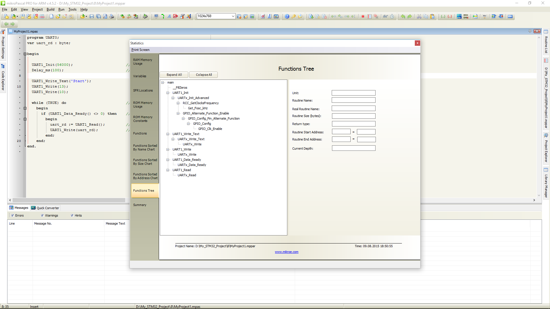
As you can see, the conclusions are automatically transferred to an alternative mode and clocking is enabled for them.
And finally - let's get to USB. The easiest. We make a HID device that simply returns the received message.
Or a similar action using Interrupt:
For normal operation of this program (and any program that uses the standard USB library), it is necessary to generate the USBdsc.mpas file. It contains the USB parameters for this device. At once I will tell, from the “Tools” menu there is a utility “HID Terminel”. This utility allows you to create the correct file, sufficient to run examples and simple applications. And if something more complicated - see the description of the USB bus. And rule the file. Fortunately, he generously provided with comments.
Using this utility, we check the operation of the example:
Of course, there will be a bunch of grunts about the “inefficiency” of the code. But look - a rather “hard” example with USB HID takes 1.7% of flash and 1.2% of operative memory.
And a small digression.
All this “magic” machinery works only with the correct setting of the clocking system. If the absolutely correct code starts to “freak out”, the external interfaces start to “disappear” and the USB interface connection generates the message “Device ID Request Error” - open the project settings and check the clocking again.

All this shows that knowledge of C is not a prerequisite for effective programming of the microcontroller. And the availability of standard libraries significantly reduces the entry threshold for unprepared people. At the same time, the code is quite compact and readable.
A detailed description of the programming environment will be written in a separate article.
PS: Actually, I know C (C ++). Freely read and understand the code. But writing programs in this language is “uncomfortable” for me. Brains automatically give access to Pascal-like code.
But what are the actual problems? stm32vldiscovery was on the shelf and was waiting for its time, I know programming and often write “to order”. I am good friends with iron.
The first thing to ask was “what to write on”? There are many programming environments, but the language is only “C”. No options. Assembler does not consider in principle. You can blink the LED, but something more complicated requires huge labor costs.
')
But I do not know Si! At all. All his life he wrote only on Pascal / Delphi. Learn the language? Have you tried to learn a language when you are over 40 years old? When work, family and minimum free time. When the mind is not as sharp as in youth. And it makes no sense to start all this for the sake of one project, than to study for the rights and buy a car for the sake of going to the bakery in the neighboring house.
The way out was the found “mikroPascal PRO for ARM” from MikroElektronika. To be honest, I already worked with “mikroPascal PRO for PIC” at the peak of PIC chip popularity. Impressions were not very good. The compiler is “weird”, the shell is also not very stable and friendly interface.
It was especially interesting to see what has changed over the years and in what direction.
And so, what we have on hand:
- Fee stm32f4discovery;
- mikroPascal PRO for ARM with a license key (taken from a friend, then have to be returned). Without a key - a limit of 2 kV on the size of the code;
- An engineer who was taught at the university exclusively Pascal.
Task: to master the programming of the microcontroller without a single line of C code.
So let's start ...
Creating a project is easy. File -> New -> New Project.
Specify the type of microcontroller. Ask what standard libraries we use (by default - everything). Leave. “Extra” libraries will be thrown out automatically when compiled.
Do not forget to configure the tactics. If in doubt, use one of the standard “Scheme”. This is a set of settings for clocking options.
First of all, let's play around with LEDs. Let's just ask them to burn. I remind you that the LEDs are located on the ports D12, D13, D14 and D15.
Code
 program MyProject1;
 begin
   // initialize the output port
   GPIO_Digital_Output (@GPIOD_BASE, _GPIO_PINMASK_12 or _GPIO_PINMASK_13 or _GPIO_PINMASK_14 or _GPIO_PINMASK_15);
   // we light
   SetBit (GPIOD_ODR, 12);
   SetBit (GPIOD_ODR, 13);
   SetBit (GPIOD_ODR, 14);
   SetBit (GPIOD_ODR, 15);

   while true do nop;
 end.
Stop! Now a huge number of people who have experience with these microcontrollers will have a question: where is the port clocking enabled ?!
Very simple: during port initialization, input or output clocking is enabled automatically. Do not believe - go View-> Statistics-> Functions Tree (my favorite!).
If there is any doubt that the compiler makes it “automatic,” go and see. Looking at the burning LED is certainly nice. But boring. Let's ask him to blink
Code
 program MyProject1;

 begin
   // set pins for exit and entry
   GPIO_Digital_Output (@GPIOD_BASE, _GPIO_PINMASK_12 or _GPIO_PINMASK_13 or _GPIO_PINMASK_14 or _GPIO_PINMASK_15);

   while true do begin
       if TestBit (GPIOD_ODR, 12) then ClearBit (GPIOD_ODR, 12) else SetBit (GPIOD_ODR, 12);
       Delay_1sec;
   end;
 end.
There is a button on the board. Let's run it to work. When the button is pressed, the LEDs light up. And when you release - go out (though unexpectedly! - a joke). The button is on A0. For reading, use the Button function. It can suppress contact bounce and takes into account the logic of the button (NC or NO). In principle, you can easily read the status of the port bit "directly", but it is more readable.
Code
 program MyProject1;

 begin
   // set pins for exit and entry
   GPIO_Digital_Output (@GPIOD_BASE, _GPIO_PINMASK_12 or _GPIO_PINMASK_13 or _GPIO_PINMASK_14 or _GPIO_PINMASK_15);
   GPIO_Digital_Input (@GPIOA_BASE, _GPIO_PINMASK_0);
   while true do
     if Button (GPIOA_IDR, 0, 10, 1) then begin
       // we light
       SetBit (GPIOD_ODR, 12);
       SetBit (GPIOD_ODR, 13);
       SetBit (GPIOD_ODR, 14);
       SetBit (GPIOD_ODR, 15);
     end else begin
       // extinguish
       ClearBit (GPIOD_ODR, 12);
       ClearBit (GPIOD_ODR, 13);
       ClearBit (GPIOD_ODR, 14);
       ClearBit (GPIOD_ODR, 15);
     end;
 end.
Direct button polling in a loop? It is not always possible to constantly check the button. Often the crystal is busy with more important things than polling the buttons. And we can just “miss” the moment of clicking. It will be more correct when you click the button to generate an interrupt, where we process the event.
Code
 program MyProject1;

 procedure INT_EXTI0 ();  iv IVT_INT_EXTI0;  ics ICS_AUTO;
 begin
   EXTI_PR: = $ FFFF;  // clear flag
   if TestBit (GPIOD_ODR, 12) then ClearBit (GPIOD_ODR, 12) else SetBit (GPIOD_ODR, 12);
 end;

 begin
   // set up conclusions
   GPIO_Digital_Output (@GPIOD_BASE, _GPIO_PINMASK_12);
   GPIO_Digital_Input (@GPIOA_BASE, _GPIO_PINMASK_0);

   EXTI_IMR: =% 1;  We allow interruption from the necessary input.
   EXTI_FTSR: = $ FFFF;  Interruption on arrival 0

   NVIC_IntEnable (IVT_INT_EXTI0);  // Enable External interrupt
   EnableInterrupts ();

   while true do;
 end.
What we have is idle in the crystal? Timer? Let's play with the PWM mode. What is the conclusion? The 4th timer comes to the conclusion that it is connected to the LED. So what are we waiting for?
Code
 program MyProject1;
 var
   ratio, tmp: word;
 begin
   ratio: = PWM_TIM4_Init (25000);
   tmp: = 0;
   PWM_TIM4_Set_Duty (0, _PWM_NON_INVERTED, _PWM_CHANNEL1);
   PWM_TIM4_Start (_PWM_CHANNEL1, @ _GPIO_MODULE_TIM4_CH1_PD12);

   while true do begin
     PWM_TIM4_Set_Duty (ratio-tmp, _PWM_INVERTED, _PWM_CHANNEL1);
     Inc (tmp);
     if tmp> ratio then tmp: = 0;
     Delay_1ms;
   end;
 end.
The timer can be used not only for PWM. Hands just itch to use a timer to perform periodic actions. Let's blink a timer for example. The timer will pull the interrupt, and the interrupt itself will control the LED.
To do this, you need long and hard to count the coefficients for writing to the timer registers. And if not - use the free software “Timer Calculator” from the manufacturer’s website.
We drive in the initial data and get the ready-made timer code. Something like this:
Code
 program ETXI;

 procedure Timer2_interrupt ();  iv IVT_INT_TIM2;
 begin
   TIM2_SR.UIF: = 0;
   if TestBit (GPIOD_ODR, 12) then ClearBit (GPIOD_ODR, 12) else SetBit (GPIOD_ODR, 12);
 end;

 procedure InitTimer2 ();
 begin
   RCC_APB1ENR.TIM2EN: = 1;
   TIM2_CR1.CEN: = 0;
   TIM2_PSC: = 2239;
   TIM2_ARR: = 62499;
   NVIC_IntEnable (IVT_INT_TIM2);
   TIM2_DIER.UIE: = 1;
   TIM2_CR1.CEN: = 1;
 end;

 begin
   // set pins to exit
   GPIO_Digital_Output (@GPIOD_BASE, _GPIO_PINMASK_12);  // Enable digital output on PORTD
   // // Timer2 Prescaler: 2239;  Preload = 62499;  Actual Interrupt Time = 1
   InitTimer2 ();

   while (TRUE) do nop;  // Infinite loop

 end.
UART? Easy too. Connect the adapter UART-USB. Let us, for example, display the value of the processor temperature every second.
Code
 program MyProject1;
 var
   uart_tx: string [20];
   tmp: integer;
   tmp1: real;

 begin
   UART2_Init (9600);  // Set the UART to 9600 bps
   ADC1_Init ();
   Delay_ms (100);  // Waiting for UART to stabilize
   TSVREFE_bit: = 1;
   UART2_Write_Text ('Hello!');
   UART2_Write (13);
   UART2_Write (10);

   while (TRUE) do
     begin
       tmp: = ADC1_Read (16);  // Read temperature data
       tmp1: = (3300 * tmp) / 4095;  // Recalculate mV.  From the calculation: 3.3 V = 4096 dc
       tmp1: = ((tmp1-760) /2.5) +25;  // Count in degrees.  V25 = 0.76VS = 2.5mV / C
       FloatToStr (tmp1, uart_tx);
       uart_tx: = 'T:' + uart_tx + 'C';
       UART2_Write_Text (uart_tx);
       UART2_Write (13);  UART2_Write (10);
       Delay_ms (1000);
     end;

 end.
We start ... The temperature of the case is -27C. This is despite the fact that in the room 23C. In principle, nothing strange. The manufacturer itself does not recommend using this sensor to measure absolute temperatures, but use it only to measure growth / decrease in temperature. The output voltage of the temperature sensor is shifted from chip to chip, and the shift can reach 45 degrees.
Stop! Did we forget to initialize the GPIO? And then there is another “proprietary” chip: when initializing a module that works “to conclusions”, the initialization of the outputs occurs automatically. Doubts? Come View-> Statistics-> Functions Tree (my favorite!).
As you can see, the conclusions are automatically transferred to an alternative mode and clocking is enabled for them.
And finally - let's get to USB. The easiest. We make a HID device that simply returns the received message.
Code
 program HID_Read_Write_Polling;

 var cnt, kk: byte;

 var readbuff: array [64] of byte;
 var writebuff: array [64] of byte;

 begin
   HID_Enable (@ readbuff, @ writebuff);
   while TRUE do
     begin
       USB_Polling_Proc ();  // Call this routine periodically
       kk: = HID_Read ();
       if (kk <> 0) then
       begin
         for cnt: = 0 to 63 do
           writebuff [cnt]: = readbuff [cnt];
         HID_Write (@ writebuff, 64);
       end;
     end;
 end.
Or a similar action using Interrupt:
Code
 program HID_Read_Write;

 var cnt: byte;

 var readbuff: array [64] of byte;
 var writebuff: array [64] of byte;

 procedure USB1Interrupt ();  iv IVT_INT_OTG_FS;
 begin
    USB_Interrupt_Proc ();
 end;

 begin
   HID_Enable (@ readbuff, @ writebuff);
   while TRUE do
     begin
       while (HID_Read () = 0) do
         ;
       for cnt: = 0 to 63 do
         writebuff [cnt]: = readbuff [cnt];
       while (HID_Write (@ writebuff, 64) = 0) do
         ;
     end;
 end.
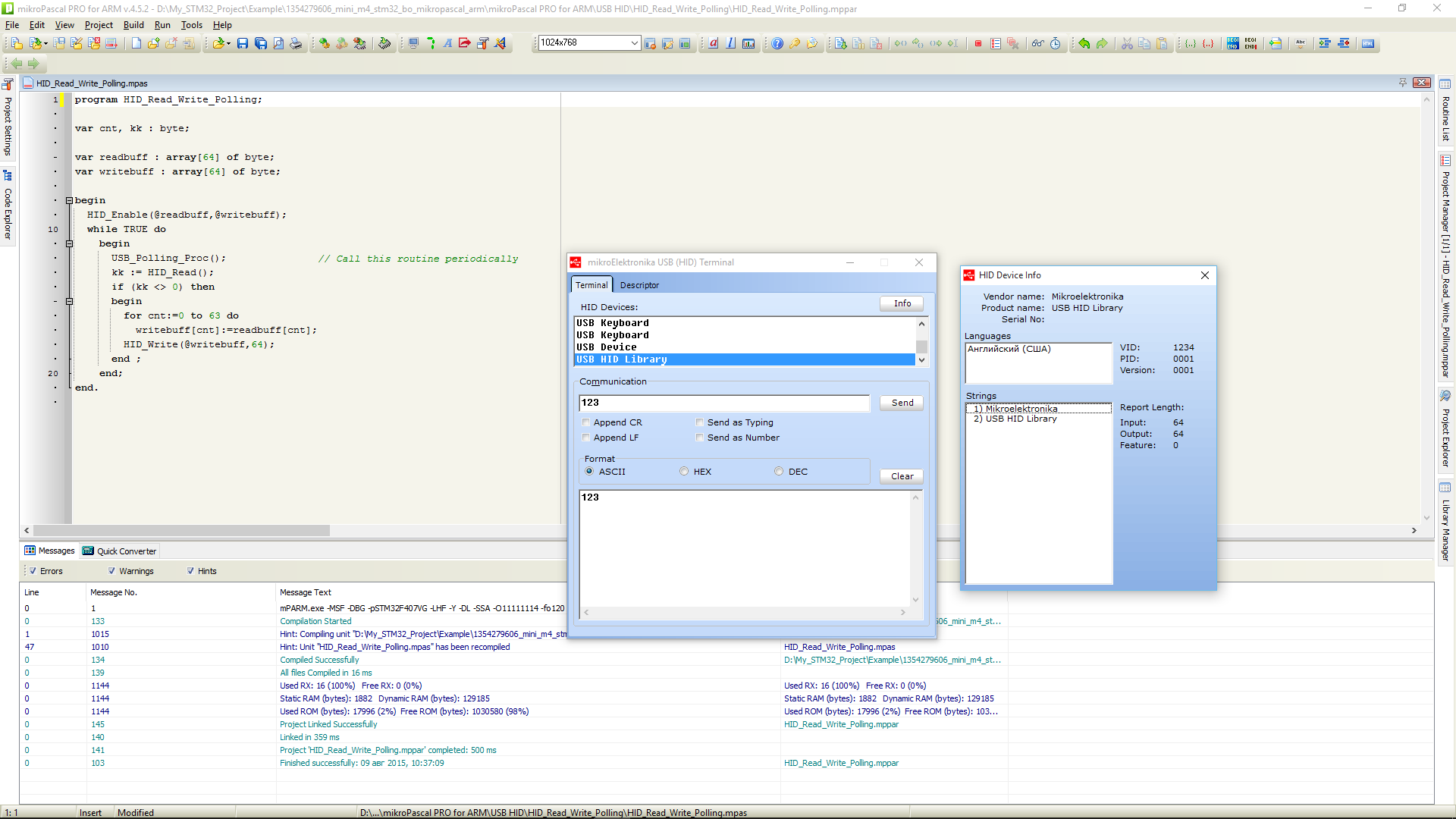
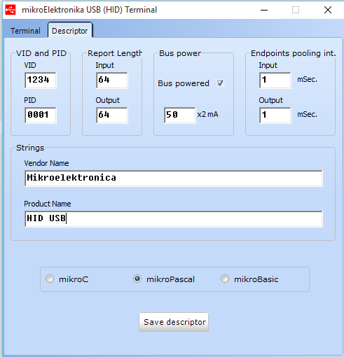
For normal operation of this program (and any program that uses the standard USB library), it is necessary to generate the USBdsc.mpas file. It contains the USB parameters for this device. At once I will tell, from the “Tools” menu there is a utility “HID Terminel”. This utility allows you to create the correct file, sufficient to run examples and simple applications. And if something more complicated - see the description of the USB bus. And rule the file. Fortunately, he generously provided with comments.
Using this utility, we check the operation of the example:
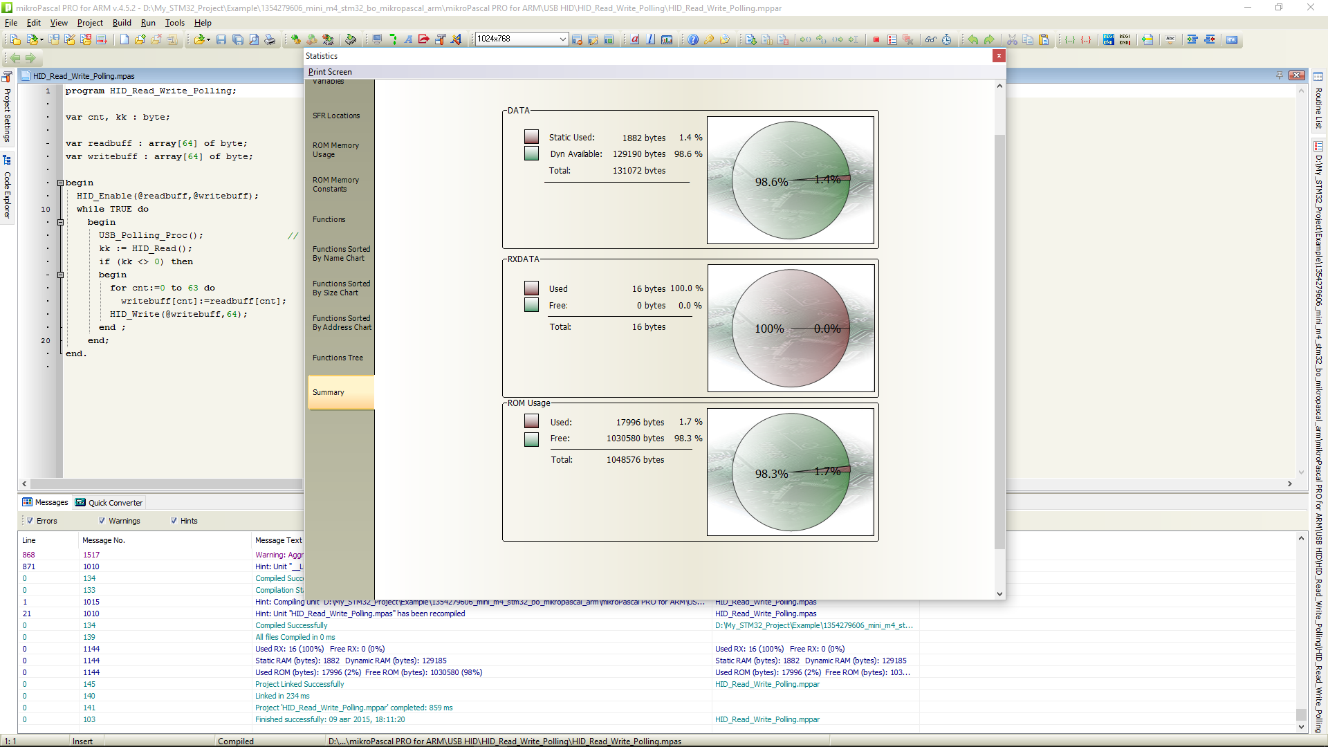
Of course, there will be a bunch of grunts about the “inefficiency” of the code. But look - a rather “hard” example with USB HID takes 1.7% of flash and 1.2% of operative memory.
And a small digression.
All this “magic” machinery works only with the correct setting of the clocking system. If the absolutely correct code starts to “freak out”, the external interfaces start to “disappear” and the USB interface connection generates the message “Device ID Request Error” - open the project settings and check the clocking again.
All this shows that knowledge of C is not a prerequisite for effective programming of the microcontroller. And the availability of standard libraries significantly reduces the entry threshold for unprepared people. At the same time, the code is quite compact and readable.
A detailed description of the programming environment will be written in a separate article.
PS: Actually, I know C (C ++). Freely read and understand the code. But writing programs in this language is “uncomfortable” for me. Brains automatically give access to Pascal-like code.
Source: https://habr.com/ru/post/264441/
All Articles