CAD technology
In this article, I offer a brief overview of geometric modeling libraries from the point of view of the developer of a specialized CAD system and share my experience in integrating the C3D core.
If the market for “large” design programs has long been divided between several large players like AutoCAD, SolidWorks, NX, Creo Elements and CATIA, etc., then the market for specialized design programs for everything and everything - windows and stairs, cabinet and upholstered furniture, pipelines and Shells are very wide and dynamic. There are two reasons for this, in my opinion: first, the high cost of buying a large CAD system and an employee who knows how to work effectively in it. And, secondly, the lack of adaptation for the design of specific products in a large CAD system leads to the fact that the speed of designing specialized products in them is low.
Specialized CAD systems are the answer to the indicated problems and there are two ways for a programmer to create them. The first is the refinement of a major CAD system using the provided API, plug-ins and all sorts of scripts. This approach is not always justified, since As a result, the cost of CAD increases for the user (you need to pay for both large CAD and adaptation), and the required qualifications of the engineer (and, consequently, the cost of his training and maintenance) to work with such a combine are quite high. The second way is the creation of a system from scratch. This path is undoubtedly more difficult, because huge functionality needs to be developed from the very beginning. But despite this, it can be much cheaper and easier to use for the end user, which determines the success of the product.
Creating a niche CAD system is undoubtedly a very expensive development, in which the algorithms of geometric modeling of three-dimensional models bear enormous complexity. Libraries that will help you in this task will be discussed further. But before starting the review, I want to determine the functionality that we wanted to get from the geometric kernel. Since our CAD is designed for furniture design, the requirements are as follows: the ability to model flat plates of arbitrary shape with cutouts, profiles with a constant cross section, bodies of rotation and, so-called curved panels and the operation of constructive geometry on these bodies, building projections and sections.
')
From an applied point of view in CAD, all geometric modeling solutions can be divided into three groups - using a polygonal, voxel and boundary representation. Polygonal modeling of objects is the generation of objects as a set of polygons, usually triangles, which are further visualized using graphic APIs like OpenGL or DirectX. This method is the easiest to implement. Creating polygonal bodies and constructive operations with them can be written independently or use open libraries, for example, CGAL. We have used such a self-described implementation for many years and it has fully justified itself: cheap and cheerful. Thus, for quite a long time we modeled rather complex furniture products, for example, curved facades, without much hassle. However, polygonal representation has significant drawbacks, which ultimately forced us to look for alternative solutions. These drawbacks are the following: in polygonal models there is no information about the bounding bodies of curves (arcs, circles, splines) on surfaces, and this significantly complicates the work of the designer, making it difficult to build accurately from non-planar surfaces (for example, cylindrical, conical, spherical, parabaloid), the quality of geometry is reduced in constructive CSG operations, it makes impossible the creation of correct drawings of the designed objects, the calculation of the exact areas of surfaces, volumes of bodies, etc. Voxel modeling is also quite specific and not intended for solving typical construction problems.
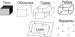
An alternative solution is to model objects using a BREP boundary view. BREP is a representation of three-dimensional bodies that describes the boundary of these bodies as a set of connected faces, and each face is a contour on the surface (for example, flat, cylindrical, spherical, conical, or NURBS).
 This method is free from the drawbacks of polygonal models (although it uses polygonal models as an intermediate step for visualization or calculations) and it is used in the vast majority of CAD systems. However, the mathematical apparatus for such modeling is incommensurably more complicated, and the choice of libraries is rather limited. Most of them are written in C ++ and some have wrappers for use in other languages.
The leaders in this area are the cores of Parasolid and ACIS . They are used in the vast majority of CAD. Along with them are known CGM and Granite , the components of large CAD systems Catia and Creo Elements, which recently became available for licensing. All of them have the most powerful functionality, are well tested and optimized. Their only drawback for our brother is the price. Very impressive annual payments, coupled with large interest payments from each sale, make the creation of small CAD on their basis a costly event.
Solids ++ and SMLib are two not very well-known commercial libraries and I could not find information about CAD systems built on their basis. According to the descriptions on their sites, both of them implement operations typical of geometric kernels. How stable and reliable they work is an open question. SMLib has a very significant advantage - unlike all other commercial libraries, it is sold along with the source code.
The only available domestic development at that time was the C3D core developed by ASCON for Compass. At the moment of choice, it only entered the market and became interested in a balanced price-performance ratio for us. At the time of the choice of the kernel, the RGK also appeared on the horizon - an ambitious domestic project, articles about which have already appeared on the habr http://habrahabr.ru/post/180455/ and http://habrahabr.ru/post/180707/ , but after a few For years, no data about him can be obtained even on the official website. And the official mail does not respond to letters.
The last kernel in question, OpenCASCADE, is the only free solution. Based on it, the famous FreeCAD package has been created. The kernel undoubtedly has developed functionality and, in my opinion, a fairly convenient API, but, unfortunately, a sufficiently large number of flaws, which, when tested, expressed in the form of irregular geometry during subtraction of bodies with coinciding edges and errors of generating projections and silhouettes of parts . But do not forget that this is an open project in which, if possible, you can correct errors yourself. This core can be used in commercial products for free, but do not forget that the additional modules ( http://www.opencascade.org/support/products ) and technical support will be paid.
Fully compare the above packages, of course, is impossible without hard work with each of them, but an approximate idea of their functionality can be obtained from CAD systems based on them. Based on our financial capabilities, we had a choice between either free OpenCASCADe or domestic C3D. The choice was made in favor of the C3D because of the greater stability, which was extremely important, because required to import a huge number of models created on your engine. And at first glance, OpenCASCADE is hard to predict how long it will take to tinker with fixing its bugs. It was also important to have the import / export of DXF and stable algorithms for generating projections and silhouettes in the C3D core. However, if our tasks were less specific, then perhaps OpenCASCADE would be a more profitable solution.
As a result, we decided to introduce the core from ASCON, which took us a long time and I want to share this experience with the readers. The C3D core represents a set of C ++ classes describing BREP models, auxiliary classes and a set of algorithms designed as global functions. At the first stage of implementation, it was necessary to decide how to connect the C ++ core to the program, which, for historical reasons, was written in Delphi. Writing a C-interface for all necessary functions seemed like a tedious and inflexible approach. The way out was found quite quickly - to write an intermediate "interface" DLL in C ++ using purely abstract classes that can be directly used in Delphi, since they contain within them a pointer to VMT, the format of which, to our happiness, is completely the same for compilers from MS and Embarcadero. As a result, I wrote a DLL-layer, which provides the necessary functionality in OOP style and exports only one function from the DLL - getting the main interface.
The next stage is the construction of all the necessary bodies in the C3D core from the initial data, their triangulation and getting the triangulation back for visualization. In this part there was no difficulty. Based on the construction functions of ExtrusionSolid, EvolutionSolid, the bodies are constructed, and using the BooleanResult functions, they are combined with each other by subtraction, addition, and intersection. At the output, they form MbSolid bodies that contain BREP data - MbFace faces, MbEdge edges, etc. Everything seemed wonderful, until I started testing more or less complex models - building a huge number of objects without caching was not very fast - the speed dropped 10 times compared to the samopisny approach, which we absolutely did not like. Here we must pay tribute to the TP of C3D - they helped to rewrite the functions of constructing the most common bodies “manually”, i.e. we began to build some bodies independently creating each facet of the body and describing all the edges on them and connecting them with each other, getting the correct closed body at the output.
The next step was visualization - pick up triangulation from C3D and draw it. The task seemed simple (considering the existing render on OpenGL), but an unexpected snag came to us: rendering objects with textures is extremely important for us, and there is no explicit support for texture coordinates in the C3D core (apparently because they are not in Compass 3D). It was necessary to get out as follows: the core allows you to generate the so-called parametric coordinates for the triangles and for each face you can calculate the scaling factors, which will allow you to impose a texture more or less realistic. However, this method does not allow to calculate the texture coordinates associated for several faces. I had to write additional “crutches” and use the attributes to associate the texture coordinates on the faces with each other. In addition, to visualize and edit models, you need to transfer various data, which I also recommended to save using attributes, which are arrays (name-value) that can be assigned to bodies, edges and edges.
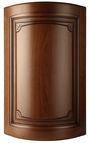
The most difficult part of the integration was the modeling of the bodies of curved facades.
Building such a body has proven to be a very time consuming task. This task revealed three major core deficiencies for our tasks: the lack of deformation operations, constructive operations in bodies containing ruled surfaces and problems with accuracy, which are aggravated by the low accuracy of the self-written core, the models from which it is necessary to maintain and the inability to control tolerances in core c3d.
The final stage of integration was various export / import operations (STEP, DXF), body relative position analysis, and the like. I want to say a single word about debugging during which a significant number of errors were detected in the kernel, which fortunately were more or less quickly resolved by the developers. Here I want to summarize the main problems we encountered:
1. Insufficiently convenient and structured API with a lot of legacy code, separation of all types into 2D / 3D and inconvenient and non-uniform functions in 2D, self-written types and structures repeating STL, but much less convenient
2. Undocumented mechanisms of forming names for all elements of the structure and the need to transmit them even if they are not used
3. The need to bring all the data to an accuracy of the order of 1e-6, the lack of precision control and the various errors that occur when it is not followed.
4. Lack of operations for constructing the path of milling and deformation of bodies.
In general, geometric modeling kernels are very complex software, and various kinds of problems with their integration are inevitable. In our case, the transition from an internal solution to a full-fledged core saved a huge amount of time and solved a whole layer of accumulated problems and the only thing we should regret is that we did not bother to search for ready-made libraries initially. We can distinguish the following advantages from the transition to a full-fledged geometric core:
1. Saving a significant amount of time (spent on creating and maintaining your own solution)
2. Improved quality of the created geometry, correct construction of curved surfaces and borders.
3. Getting quality drawings with the removal of invisible lines
4. Export / import into “Saprovsky” 3d formats (STEP, SAT, XT, DXF)
I hope that if one of the readers has experience working with similar libraries, then I will also share the experience of their implementation.
Source: https://habr.com/ru/post/264243/
All Articles