My system is testing and improving the quality of the GSM gateway. Part two
In the first part of the article I told the background of the FXS GSM gateway with the recording of the conversation, explained what mistakes were made in the first version, as were corrected in the second version. The heart of the gateway has become a microcontroller that manages everything: power, sound (digital and analog), telephone line.
A self-diagnostic function has been implemented in the circuit. For this purpose, measuring circuits, power control and handset lifting circuits, a circuit for load testing of power and critical nodes were added to the gateway. For communication with a PC and flashing a USB-USART bridge is installed, which can work as a programmer.
')
In this and the next article I will talk about the test firmware: how it tests all the peripherals, what ideas were embedded in it and how they were implemented using the example of test log analysis.
Test firmware checks:
- Clock frequency, accurate to ppm.
- All power lines.
- All the legs of the processor.
- LEDs.
- The source of the telephone line.
- Sending and receiving sound from the telephone line. Frequency response , SOI noise level.
- GSM module.
- SD card.
Test log entirely
I did not find a single article on the habr about the program of production testing of an actual product. Therefore, I hope I am the first. If not, I would love to read articles from others.
Elements of the diagnostic system
Test firmware for the initial diagnosis and screening after assembly. Performed in the device. Makes all diagnostics without the help of a PC. Produces results in a production program on a PC. When you first start, it runs all the tests. Subsequent requests that what to do: either run all the tests, or one group of tests to choose from, or manual control mode.
The main firmware for customers. Performed in the device. It is flashed automatically by the production program after successful tests without a single error.
The PC production program is a complex of several programs that flushes the gateway with test or basic firmware for the client. It connects to the device and logs data from it. Sends the pressed buttons F1 ... F9, ESC to the running firmware. Keeps an archive of logs. Logs IMEI, serials, firmware versions and user action logs. Calculates statistics, the number of errors. Performs synchronization between the workplaces of builders, developer and metrologist. Allows you to cut logs for a given parameter, etc. About this in the third part of the article.
The test echo gateway is a gateway with a special firmware, which in the echo mode produces a received sound to the GSM network. Used in the test firmware for a trial outgoing call, for testing the sound over the GSM channel and checking the stability of the GSM module.
A simple firmware program , a simplified version of the production program, allows you only to flash and get the log from the device without the ability to control the firmware and keep the remaining logs with a statistics calculation. It is provided to clients for diagnosis. It also allows you to update the firmware through our bootloader with firmware encryption.
The web server is used to synchronize data, archive and backup logs and reports, to issue the firmware GPRS-loader.
Ideas implemented in the test program
Log convenient for production. In this log, all data of the same type must be aligned into tables, the values are signed with clear values, the limits of tolerances are indicated. All actions are shown, including dummy messages that help you understand whether the program is frozen or not.
Log convenient for the developer. Intermediate indicators are derived, on the basis of which final indicators are calculated, on which conclusions are made. In the log should be service information: the date of the source, a unique ID from the MK.
Log convenient for a metrologist. All measurements must be excessively accurate (for example, millivolts, millidebicles, etc.). This allows you to see how close the value has come to the border of the range or how much it has exceeded the border. If there is a lot of data and the limits are not indicated for the entire line, then the rating of the indicator, which deviated the most, is displayed. Due to this, it is convenient to run through the eyes of the rating figures and see that some indicator has come close to the range boundary. The rating is at the end of the line the last digit from -9 to +9, where 0 is the middle of the allowed range.
Indication of communication channel failure. The log displays characters only in 7-bit ASCII mode, only in Latin on my curve aglitsky. The serial port is configured for 8 bits with parity. In a production program that displays a log, all lines with characters that have code less than 32 or more than 127 are counted as errors and are displayed in bright red.
Convenient processing by third-party programs. For this, all measured values and tables of values are framed by tabs. This format is convenient to use in the database or Excell. The production program should be able to highlight the rate of one color, and the error - a different color. For this, the standard is signed with the word “OK”, and the error - “ERROR”. Norms and errors are counted, their statistics and indexing are in progress.
The possibility of statistics. Each parameter must have its own unique name. By this name in the production program, you can cut across all the logs, see how the selected parameter has changed, and build a graph.
Self sufficiency. Tests should test multiple parameters many times and in different ways. They must be redundant. As many indicators as possible should be duplicated by other direct and indirect measurements made by other algorithms and methods. Otherwise, it will be unclear what fails: the circuit, the board, the testing algorithm itself or the wrong actions. Yes, and in the analysis it is much easier to see the totality than to make yourself a “keyhole” into one single measurement.
The log should not be huge. Part of the parameters had to be done without a signature limit, because There are a lot of them, and the log should not exceed ten pages.
The hardest part was to combine all these requirements. Due to the size limit, we had to sacrifice the convenience for production and make a crutch with a rating of -9 ... +9. Other things, such as the definition of email. parameters of each pin, also had to be turned into "magic numbers", adding some kind of conclusion for each pin. Production still criticizes me that there are quite a few obscure meanings, but this is such a compromise. Something was left, simply because it was crookedly done, and it was too late to redo it - people got used to it.
Testing Log Description
Enable and service information
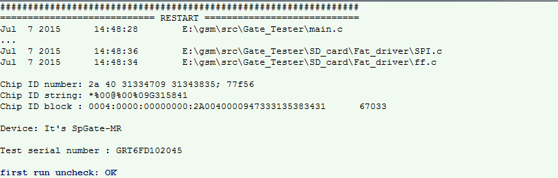
At the start of the test firmware, the header and the compilation dates of all files included in the project are displayed. Next, a unique Chip ID number is issued in three formats, two of which are protected from manual modification with a 16-bit hash, which is considered to be two different algorithms.Next, the serial number is displayed, and it defines the type of gateway and selects a testing profile. At the moment there are three types of gateways: with recording of conversations, without recording of conversations, small size and budget without recording of conversations and without USB. Circuit design of all three is the same, except for the presence of USB and SD-card.
Further the flag of the first start is checked and reset. If the first run, then run all the tests. If not, a launch menu is displayed.
Check quartz clock frequency

The following is checked: whether external quartz is running at 8 MHz, if the quartz instability protection has not worked, whether both PLLs are running and working stably, whether the final frequency corresponds to the required one. One PLL for peripherals and cores multiplies the frequency up to 160 MHz, and the other divides the frequency up to 256 kHz for digital I2S sound into a GSM module.Only after checking the clock frequency does it make sense to check the remaining parameters.
Check quartz watch

Quartz is launched, the time for which it was launched is displayed. Next, one second is measured in base frequency clock, and the deviation is calculated in ppm relative to the base frequency of 160 MHz.Verification of main voltages

Within a second, 100,000 samples are taken over a specific ADC channel.and the following indicators are calculated (from left to right):
- constant component (in millivolts taking into account dividers on resistors);
- low frequency component (if it is significantly higher than the high frequency component, then these are pickups from the network);
- high-frequency component (if it is significantly larger than the low-frequency component, then it is a crash or an unstable ADC);
- maximum range in ADC samples;
- The worst score is from -9 to +9.
This test is used further in many other tests.
Measured values:
- DIAG_SENS - GSM-module power sensor (in the initial state it is turned off and should not “miss” and make noise);
- SLIC_LINEU - voltage in the telephone line (in the initial state, the line should be turned off and not make noise);
- FXS_ADC - sound from the telephone line (not issued during the test - it means there should be silence and half power);
- DVCC - digital power supply MK (there should be no noise);
- SD_VCC - digital power to the SD card (must be turned off);
- 12V_PWR - general power supply 12 V;
- DVCC-Vbat - digital power supply of the watch module from a lithium tablet battery;
- VrefInt - internal reference voltage of 1.2 V (they check analog power supply and ADC support);
- Temp in C - temperature and its change after the second measurement after running all the tests (the gateway should not heat up).
Check for short circuit legs MK to the ground or power
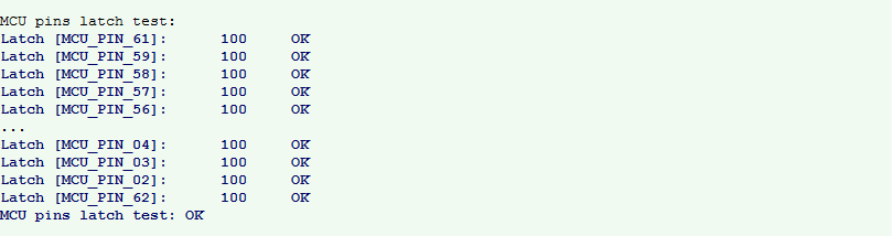
All MK legs are checked, not even connected. This is done to control the quality of the soldering.They are checked by writing “0” and checking that “0” is read. Then “1” is written and the reading of “1” is checked. So 100 times, because different peripherals are connected to a number of legs, which can give a false positive with a single test.
Check for short-circuit adjacent legs MK among themselves
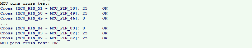
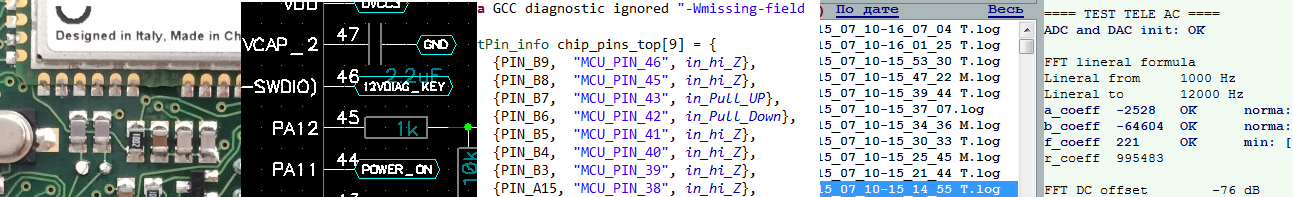
Similar to the previous test, only the recording is made on one leg of the MK, and the reading is from the next. There are also 100 attempts: 50 of them in one direction, 50 in another. Numbers indicate successful attempts. The values 25 ... 50 are obtained because part of the legs is connected to a working circuit, and a fixed value of “0” or “1” is fed to them, therefore, part of the tests reveal false positives. Because of this, the threshold is chosen close to 100.Checking the electrical parameters of the legs MK

And here is the magic that works like this:1. The foot is adjusted to the output "1", then transferred to the input mode and measured the time it takes to go to "0".
2. The foot is adjusted to the output "0", then transferred to the input mode and the time is measured, during which it will go to "1".
3. and 4. Similarly to p. 1 and p. 2, but translated into a mode with a lift to the ground or power - this helps to quickly move to "0" or "1".
These actions can measure the capacity at the leg and the presence of braces, even high resistance. But the measurement is very rough, because the delays depend on the size of the suspender inside the MC, and it can change 10 times. There is also a dependence on temperature, which can vary widely.
Time values are presented on a logarithmic scale. According to the results of the implementation of paragraphs 1..4, these values are written in the first four numbers in each line.
All legs are checked, including the UART. In this case, the UART are bad symbols.
The types of parameters in this test are:
- hi_Z is a high-impedance state with a very small capacity, less than 10 pF;
- hi_Z + C_pF - high-impedance state with a capacity of 10 ... 1000 pF;
- hi_Z + C_nF is a high-impedance state with a capacity of 1 ... 1000 nF;
- hi_Z + C_uF is a high-impedance state with a capacity of 1 µF and above;
- Pull_Down - low impedance lift to the ground;
- Pull_Down_M - high impedance lift to the ground;
- Pull_Up - low impedance power supply;
- Pull_Up_M - high impedance power lift;
- FIXED - the condition of the legs does not depend on the actions on it;
- (empty line) - the state could not be determined (for example, on the leg to which the OU output of the sound from the line is connected).
Check two color LEDs
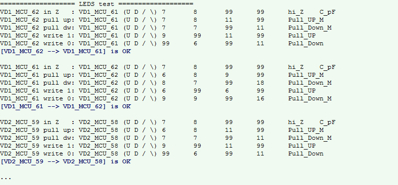
Each two-color LED represents two oppositely-on LEDs of different colors. The essence of the test lies in the fact that 1 or 0 is fed to one leg of the LED, or a pull-up to ground or power, or high impedance. And on the other leg of the LED, the reaction of the electrical state to this effect is checked. Then they switch places and the decision is made based on the results.For example, at the 62 terminals, we turn on the “VD1_MCU_62 pull up” power-up pull-up, measure the state of the 61-pin - it also became a pull-up, but high-resistance “VD1_MCU_61 Pull_UP_M”.
Not all LEDs are turned on equally, some have braces or other functions. This is taken into account in the LED test log. For example, this behavior can be seen on the test results, if you look at the full log and compare it with the MK scheme from the first article .
In the next part, I will tell you how the telephone line is checked (voltage source, sound output and reception), SD card, power supply under load, and how their parameters are calculated. And at the end of the article I will draw conclusions and conclusions on the test firmware.
Source: https://habr.com/ru/post/264045/
All Articles