Channel Status Protocols and Single-Zone OSPF (Part 1)
 Coming up with the best way to explain something, I almost always find the best way to understand it for myself.
Susskind L., Grabowski J.
The theoretical minimum.
Everything you need to know about modern physics. *
Translation of a chapter from the book by Chris Bryant "CCNP Route Study Guide". His site is thebryantadvantage.com . The book is available on amazon .
Of all the videos viewed, read books to prepare for CCNP ROUTE, the material from this seemed the easiest to learn. Allows you to sort everything out. In addition to theory, I also liked practical examples. At the end of each chapter there are links to youtube lessons.
Basics of channel status protocols
You are familiar with the behavior of the channel status protocols from the CCNA course, but now we are going to review the important points.
')
Avoid the temptation to miss a review.
In the meantime, quite a bit of you will be familiar - there are many additional details that you should master like CCNP. For those who are going to take CCIE, you need to really learn how OSPF works.
When RIP sends route updates, they contain the complete routing table. Including debugging with the debug ip rip command, you can see the routes contained in the update along with the metric.
Channel state protocols work differently. Channel state routers that have created a neighborhood exchange LSU packets that contain LSA announcements. These LSA announcements carry subnet mask information and allow OSPF to support variable length masks (VLSM).
LSA announcements are placed in the channel status database. Dijkstra's algorithm (also known as the first shortest path search algorithm, SPF) works with the contents of this database to create an OSPF routing table.
Routers must synchronize their link state databases.
To view the contents of the link state database, enter the show ip ospf database command. This command shows the channels and connection types, sequence numbers and how long a certain LSA announcement was received. This value in seconds can be viewed in the "age" column.
Dijkstra's algorithm works with the contents of the database ...
R1#show ip ospf database OSPF router with ID (1.1.1.1) (Process ID 1) Link ID ADV Router Age Seq# Checksum 1.1.1.1 1.1.1.1 1286 0x80000006 0x0057A7 8.8.8.8 8.8.8.8 795 0x8000000C 0x00085E Net Link States (Area 0) Link ID ADV Router Age Seq# Checksum 10.1.1.5 8.8.8.8 795 0x80000006 0x001CC3 ... computes routes, and these routes are placed in the OSPF routing table
R1#show ip route ospf 6.0.0.0/32 is subnetted, 1 subnets O 6.6.6.6[110/11] via 10.1.1.5, 02:32:53, Ethernet0 7.0.0.0/32 is subnetted, 1 subnets O 7.7.7.7[110/11] via 10.1.1.5, 02:32:53, Ethernet0 The SPF algorithm actually calculates the shortest path along the tree, and this tree is used to create the routing table. We should not think more about this algorithm, since it does everything perfectly well without our intervention, but we have a lot of details that are worth paying attention to!
LSA sequence numbers
In order to ensure that OSPF routers receive the latest information, LSAs are assigned sequence numbers. When a router with OSPF receives LSA, it checks against its database whether there is an entry for this channel or not.
If there is no record, the router creates it and sends this LSA announcement to all OSPF interfaces, except for the one on which this message was received.
If there is an entry, then several options are possible. Depending on the value of the LSA sequence number, it is greater, less or equal to the one contained in the database.
- If the number matches, the LSA announcement is ignored and no further action is taken.
- If the number is smaller, the router will ignore the update and send the LSU packet containing the LSA announcement back to the sender. In this situation, a router with more recent information informs the sender: “The information you send is outdated. This is the one that should be sent. ”
- If the sequence number is higher, the router will add this LSA announcement to its database and send a LSA acknowledgment. Then the router will send this LSA announcement and run the SPF algorithm to update its own routing table.
When is the LSA announcement exchange?
Remote-vector protocols send updates regularly at a certain time interval, regardless of whether there were changes in the network topology or not. For a stable network, it is a waste of resources. After the initial exchange of LSA announcements between two OSPF neighbors, another exchange of announcements does not occur until the network topology changes.
The OSPF router also sends out summary LSA announcements every 30 minutes.
Before exchanging LSA announcements, routers must become neighbors, forming a neighborhood. To do this, routers must have the same zone number, hello and dead timers, and you need to check whether the zone is a “stub” zone. If there is authentication, then it must be configured on both sides of the channel.
The OSPF process number itself is locally significant and does not affect the establishment of the neighborhood.
To check the neighborhood, enter the show ip ospf neighbor or less commonly used show ip ospf interface command. This last command is often forgotten, but it gives a lot of useful information.
Note that both commands will show you which neighborhood relationships exist, and only show ip ospf neighbor will show the status of the database load (FULL, 2WAY, etc.)
R3#show ip ospf neighbor Neighbor ID Pri State Dead Time Address Interface 1.1.1.1 1 FULL/DR 00:01:52 172.12.123.1 Serial0 1.1.1.1 1 FULL/ - 00:00:32 172.12.13.1 Serial1 4.4.4.4 1 FULL/DR 00:00:32 172.23.23.4 Ethernat0 R3#show ip ospf interface serial0 Serial0 is up, line protocol is up Internet address 172.12.123.3/24, Area0 Process ID 1, Router ID 3.3.3.3, Network Type NON_BROADCAST, Cost: 64 Transmit Delay is 1 sec, State DROTHER, Priority 0 Designated Router (ID) 1.1.1.1, Interface Address 172.12.123.1 No backup designated router on this network Timer intervals configured, Hello 30, Dead 120, Wait 120, Retransmit 5 Hello due in 00:00:16 Index 1/1, flood queue length 0 Next 0x0(0)/0x0(0) Last flood scan length is 1, maximum is 3 Last flood scan time is 0 msec, maximum is 4 msec Neighbor count is 1, Adjacent neighbor count is 1 Adjacent with Neighbor 1.1.1.1 (Designated Router) Supress Hello for 0 neighbor(s) show ip ospf interface will give you the local OSPF router identifier (RID), its role in this segment (DR, BDR, DROther), the identifier (RID) of the DR or BDR for this segment, and more. This is a great starting point for troubleshooting.
The role of DR and BDR
The main disadvantage of distance vector protocols is slow convergence.
Convergence means the state of the network when each router has a similar look to other routers and an accurate view of the network, especially after a topology change, such as when the route is disabled. Remote-vector protocols do not converge quickly enough, which can lead to non-optimal routing and routing loops.
Channel state protocols converge almost immediately after a topology change. OSPF uses dedicated routes and spare dedicated routes for fast and correct network convergence.
How DR sends network change messages
When a router in an OSPF segment with DR and BDR notices changes in the network, it does not notify all its neighbors. Instead, it sends a multicast to 224.0.0.6, the address that both routers are listening to - DR and BDR, to be aware of such changes.
Then DR sends multicast to 224.0.0.5 - notify all non-DR and non-BDR routers in the network. (Routers that are not DR or BDR are called DROthers, as shown in the show ip ospf neighbor command output). DROthers send a confirmation (LSA acknowledgment, LSAck) back to the DR to receive the update.
Two notes:
- Only DR and BDR are listening 224.0.0.6.
- Only DR sends multicast to 224.0.0.5 to notify DROthers about changes in the network. BDRs receive them, but do not notify other routers. Listening to 224.0.0.6 gives BDR the ability to have the latest changes to the database - and this is important in case it becomes DR.
DR / BDR selection process
Almost every OSPF network segment contains DR and BDR. As always there are exceptions, and we will discuss these situations further. And now, let's take a closer look at the rules for choosing DR and BDR.
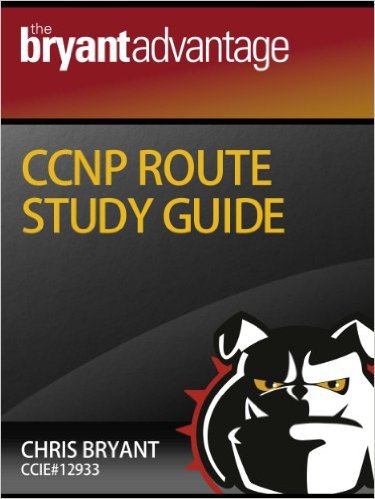
According to the following network diagram (I could put a switch in the center instead of naming an “Ethernet” segment; be prepared to see this in the network documentation).
The interfaces of the four routers are in the Ethernet segment. One will become DR, the other BDR, the rest - DROthers. Before we see how Cisco routers assign these roles, let's take a look at the process of choosing a DR / BDR.
1. All routers with interface priority 1 or higher can be selected as DR / BDR. Setting the priority to 0 deprives the router of this possibility.
2. The router with the highest priority becomes DR.
3. If they match, the values of the RID are compared. The router with the greatest wins.
4. This process is repeated to select a new BDR. The same router cannot be both DR and BDR.
Later we will discuss the interesting behavior of DROthers in the Ethernet segment. And now let's focus on the DR / BDR selection process using OSPF RID.
OSPF RID selection process
Obviously, OSPF RID plays a big role in choosing DR and BDR - but how is the RID value determined? According to the following rules:
The OSPF router RID will be the largest IP address assigned to the loopback interface, regardless of whether this interface was included in the OSPF process. It is not automatically advertised by OSPF.
If there are no loopback interfaces, the router's OSPF RID will be the highest IP address assigned to the physical interface, whether it is included in OSPF or not.
These rules can be rewritten by manually installing the OSPF RID using the router-id command, but the OSPF process (cleared) must be restarted on the router.
It seems a little strange that loopback interfaces that are not participating in OSPF determine the RID, does it?
Let's look at everything in action. R1 and R5 have formed a neighborhood in the 10.1.1.0/24 subnet. R5 has several loopback interfaces, but only two are advertised via OSPF:
hostname R5 ! interface Loopback6 ip address 6.6.6.6 255.255.255.255 ! interface Loopback7 ip address 7.7.7.7 255.255.255.255 ! interface Loopback8 ip address 8.8.8.8 255.255.255.255 ! interface Ethernet0 ip address 10.1.1.5 255.255.255.0 ! router ospf 1 network 6.6.6.6 0.0.0.0 area 0 network 7.7.7.7 0.0.0.0 area 0 network 10.1.1.0 0.0.0.255 area 0 Knowing the rules for determining OSPF RID, which OSPF RID will show R1 for R5? Look at the configuration and find out.
If you said 8.8.8.8, then you are right. To see the OSPF neighbor RID, enter show ip ospf neighbor :
R1#show ip ospf neighbor Neighbor ID Pri State Dead Time Address Interface 8.8.8.8 1 FULL/DR 00:00:37 10.1.1.5 Ethernet0 The value specified under Neighbor ID is the neighbor RID.
To illustrate another important thing regarding DR and BDR, let's go back to our four-router example. Routers have the following addresses:
RouterA: Loopback 1.1.1.1, ethernet0 172.1.1.1 RouterB: Loopback 2.2.2.2, ethernet0 172.1.1.2 RouterC: No loopback, ethernet0 172.1.1.3 RouterD: No loopback, ethernet0 172.1.1.4 RIDs will be:
RouterA: 1.1.1.1 RouterB: 2.2.2.2 RouterC: 172.1.1.3 RouterD: 172.1.1.4 The RID selection process always prefers IP addresses of loopback interfaces over physical ones.
In summary, we have three ways to influence the RID value:
- Changing OSPF priority using the ip ospf priority command
- Install RID manually using router-id
--Install RID by configuring loopback interface
None of these methods is “erroneous” or “correct” - so know all three, and know that you need to restart the OSPF processes to apply the changes.
What happens if the DR is turned off and then on?
If all four routers are on at the same time, we expect that router D will be DR and router C - BDR. But what if router D turns off and then turns on?
If there is no router D, router C becomes DR. Router B will be BDR. And then router D is turned on, but routers C and B retain their roles.
This is not like the spanning tree protocol, where the new switch, with a lower BID, becomes the root switch. In OSPF, the choice of DR / BDR does not change when you turn on the new router or turn on the one that was previously DR or BDR.
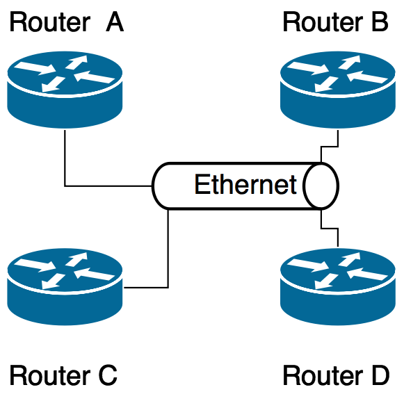
Let's look at an example with three routers in an Ethernet segment. The priority of router A is 100, B is 50, C is 10. Router A is selected by DR, B is BDR.

Everything is fine until Router A turns off. Routers B and C become DR and BDR respectively.
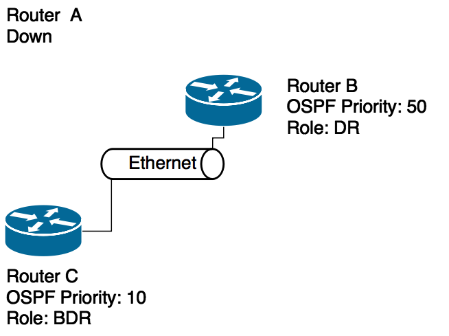
Turning on Router A is not a reason to re-select DR / BDR, even if Router A has a higher priority than DR and BDR. When enabled, Router A becomes DROther.

In order for Router A to become DR again, both the current DR and BDR must shut down! What happens when router B turns off?
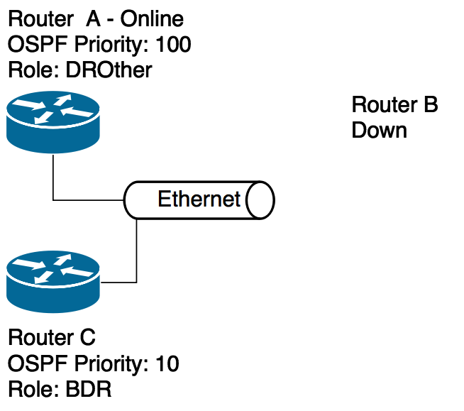
Router C becomes DR, Router A becomes BDR. When you turn on router B, it will be DROther.
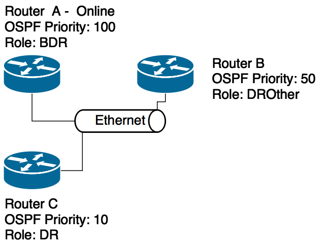
For final installation as the DR of router A, turn off router C. Now router A from BDR will become DR, and router B will become BDR.
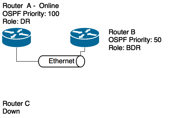
When you turn on router C, it will become DROther, and we will get the same network layout!
* I did not dare to make a headline, but still let it be PS:
Since the quote is taken from a book published by the Dynasty Foundation, then, recalling the call to progchip666 , I am writing here - “ Dedicating the Dynasty Foundation” to the liquidation.
UPD: poll updated, thanks for the tip.
UPD2: github .
Source: https://habr.com/ru/post/263943/
All Articles