Configure Ubiquiti Wi-Fi and Cisco (Guest DHCP and VLANs)
This article describes one of the ways to configure guest and corporate wireless networks using Enterprise Wi-Fi Ubiquiti UniFi and Cisco Integrated Services Routers solutions.
Recipe
Create a corporate SSID network
Create a guest SSID network
Create VLAN networks on one physical port
Configure DHCP Forwarding
Isolate guest VLAN
Release clients under different static IP
')
Ingredients
Router: Cisco 2901 Router
OS for controller: Ubuntu server 12.04
Software: Ubiquiti UniFi Controller 4.6.6
Switch: Ubiquiti TOUGHSwitch PoE Pro
Points: Ubiquiti UniFi AP LR
Topology

Cooking Cisco
Create a VLAN database
VLAN id you can use at your discretion
cisco#vlan database cisco(vlan)#vlan 1 VLAN 1 added: Name: VLAN0001 cisco(vlan)#vlan 2 VLAN 2 added: Name: VLAN0002 cisco(vlan)#vlan 3 VLAN 3 added: Name: VLAN0003 cisco(vlan)#apply APPLY completed. cisco(vlan)#exit cisco#wr Configure and create VLANs
Here we immediately nail down NAT for our clients with the ip nat inside command .
cisco#conf t cisco(config)#interface vlan 1 cisco(config-if)#ip address 172.16.1.1 255.255.255.0 cisco(config-if)#ip nat inside cisco(config-if)#ip virtual-reassembly in cisco(config-if)#ip tcp adjust-mss 1452 cisco(config-if)#exit cisco(config)#interface vlan 2 cisco(config-if)#ip address 172.15.1.1 255.255.255.0 cisco(config-if)#ip nat inside cisco(config-if)#ip virtual-reassembly in cisco(config-if)#ip tcp adjust-mss 1452 cisco(config-if)#exit cisco(config)#interface vlan 3 cisco(config-if)#ip address 172.17.1.1 255.255.255.0 cisco(config-if)#ip nat inside cisco(config-if)#ip virtual-reassembly in cisco(config-if)#ip tcp adjust-mss 1452 cisco(config-if)#exit cisco(config)#exit cisco#wr We configure and create DHCP
172.16.1.1/24 We will use for network management, namely - there our points will receive IP and knock on the controller. 172.15.1.1/24 We will distribute to guests, and we will give the network 172.17.1.1/24 to corporate devices. The example uses the DNS server Yandex: 77.88.8.8 Google: 8.8.4.4. The lease parameter indicates how many days we give IP to the client.
cisco#conf t cisco(config)#ip dhcp pool Vlan1 cisco(dhcp-config)#import all cisco(dhcp-config)#network 172.16.1.0 255.255.255.0 cisco(dhcp-config)#default-router 172.16.1.1 cisco(dhcp-config)#dns-server 77.88.8.8 8.8.4.4 cisco(dhcp-config)#lease 8 cisco(dhcp-config)#exit cisco(config)#ip dhcp pool Vlan2 cisco(dhcp-config)#import all cisco(dhcp-config)#network 172.15.1.0 255.255.255.0 cisco(dhcp-config)#default-router 172.15.1.1 cisco(dhcp-config)#dns-server 77.88.8.8 8.8.4.4 cisco(dhcp-config)#lease 1 cisco(dhcp-config)#exit cisco(config)#ip dhcp pool Vlan3 cisco(dhcp-config)#import all cisco(dhcp-config)#network 172.17.1.0 255.255.255.0 cisco(dhcp-config)#default-router 172.17.1.1 cisco(dhcp-config)#dns-server 77.88.8.8 8.8.4.4 cisco(dhcp-config)#lease 1 cisco(dhcp-config)#exit cisco(config)#exit cisco#wr We help the DHCP server
For the correct distribution of IP addresses, it is desirable to explicitly specify the ip helper-address - DHCP server on all VLANs.
cisco#conf t cisco(config)#interface vlan 1 cisco(config-if)#ip helper-address 172.16.1.1 cisco(config-if)#exit cisco(config)#interface vlan 2 cisco(config-if)#ip helper-address 172.15.1.1 cisco(config-if)#exit cisco(config)#interface vlan 3 cisco(config-if)#ip helper-address 172.17.1.1 cisco(config-if)#exit cisco(config)#exit cisco#wr Exclude the issuance of service IP addresses
cisco#conf t cisco(config)#ip dhcp excluded-address 172.15.1.1 172.15.1.3 cisco(config)#ip dhcp excluded-address 172.16.1.1 172.16.1.3 cisco(config)#ip dhcp excluded-address 172.17.1.1 172.17.1.3 cisco(config)#exit cisco#wr Configuring interfaces
After creating a VLAN and configuring DHCP, we need to configure the port on the router that will distribute these networks in a special way. In our example, we will set the GigabitEthernet 0/0 port to the primary VLAN 1 and allow us to pull the VLAN 2 and VLAN 3.
The example uses the GigabitEthernet 0/0 interface, it is assumed that you have at least 2 more ports - one for Internet access GigabitEthernet 0/1 and one port for your corporate wired network, for example GigabitEthernet 0/2.
cisco#conf t cisco(config)#GigabitEthernet 0/0 cisco(config-if)#switchport trunk encapsulation dot1q cisco(config-if)#switchport mode trunk cisco(config-if)#switchport trunk allowed vlan 1,2,3 cisco(config-if)#switchport trunk native vlan 1 cisco(config-if)#no shutdown cisco(config-if)#exit cisco(config)#exit cisco#wr Now, when the GigabitEthernet 0/0 port is connected, our controller and points will receive the 172.16.1.0/24 network, and VLAN2 and VLAN3 will be used on demand.
We tighten the nuts
Now that we have configured the primary port for all networks, it’s time to deny guest network access (VLAN2) to go to our neighboring networks.
In this example, a wired corporate network hangs on GigabitEthernet 0/2 192.168.0.0 255.255.255.0
cisco#conf t cisco(config)#access-list 110 deny ip 172.15.1.0 0.0.0.255 192.168.0.0 0.0.0.255 cisco(config)#access-list 110 deny ip 172.15.1.0 0.0.0.255 172.16.1.0 0.0.0.255 cisco(config)#access-list 110 deny ip 172.15.1.0 0.0.0.255 172.17.1.0 0.0.0.255 cisco(config)#access-list 110 permit ip any any cisco(config)#exit cisco#wr We beat this access-list 110 to our VLAN2
cisco#conf t cisco(config)#interface vlan 2 cisco(config-if)#ip access-group 110 in cisco(config-if)#exit cisco(config)# cisco#wr We route our clients with different external IPs.
In order to indicate which clients go through which external IP I use pools.
Imagine that we have 3 external IP addresses issued by our ISP: 100.100.100.101, 100.100.100.102, 100.100.100.103 with one gateway 100.100.100.1
Configuration example
interface GigabitEthernet0/0 switchport trunk native vlan 2 switchport mode trunk no ip address ! interface GigabitEthernet0/1 ip address 100.100.100.101 255.255.255.0 ip nbar protocol-discovery ip nat outside ip virtual-reassembly in duplex auto speed auto ! interface GigabitEthernet0/2 ip address 192.168.0.0 255.255.255.0 ip access-group 109 in ip nat inside ip virtual-reassembly in ip tcp adjust-mss 1452 duplex auto speed auto ! ip route 0.0.0.0 0.0.0.0 100.100.100.1 ! access-list 109 permit ip 192.168.0.0 0.0.0.255 any access-list 110 deny ip 172.15.1.0 0.0.0.255 192.168.0.0 0.0.0.255 access-list 110 deny ip 172.15.1.0 0.0.0.255 172.16.1.0 0.0.0.255 access-list 110 deny ip 172.15.1.0 0.0.0.255 172.17.1.0 0.0.0.25 access-list 110 permit ip any any So, we want clients from the 192.168.0.0 network to go to the world via IP 100.100.100.101, clients from the guest wireless network 172.15.1.0 go to the world via IP 100.100.100.102, and clients from the corporate wireless network via IP 100.100.100.103
Let's create an additional access-list 108 for clients from a corporate wireless network.
cisco#conf t cisco(config)#access-list 108 permit ip 172.17.1.0 0.0.0.255 any cisco(config)#exit cisco#wr Screw access-list 108 to VLAN3
cisco#conf t cisco(config)#interface vlan 3 cisco(config-if)#ip access-group 108 in cisco(config-if)#exit cisco(config)# cisco#wr It is assumed that you have already created the access-list 109 yourself when you set up a wired network
So, we have 3 access-list, let's go.
Create pools ( netmask should strictly correspond to the one issued by ISP )
cisco#conf t ip nat pool OFFICELAN 100.100.100.101 100.100.100.101 netmask 255.255.255.0 ip nat pool WIFIGUEST 100.100.100.102 100.100.100.102 netmask 255.255.255.0 ip nat pool WIFICORP 100.100.100.103 100.100.100.103 netmask 255.255.255.0 We beat the access-list to the pool
cisco#conf t cisco(config)#ip nat inside source list 109 pool OFFICELAN overload cisco(config)#ip nat inside source list 110 pool WIFIGUEST overload cisco(config)#ip nat inside source list 108 pool WIFICORP overload cisco(config)#ip nat inside source route-map nonat interface GigabitEthernet0/1 overload cisco(config)#exit cisco#wr At this point, the configuration of the Cisco router is complete.
Cooking controller
So, now we take the server under the controller, install Ubiquiti UniFi Controller 4.6.6 software there, I will not describe the installation process, OS of your choice, I installed Ubuntu server 12.04 and assigned IP 172.16.1.3 to the controller
Basic setting
Open the web interface of the controller 172.16.1.3 : 8443
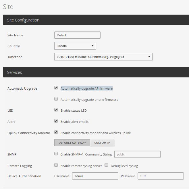
1. Go to Settings -> Site
Put the checkbox - Automatically upgrade AP firmware , and the rest to taste:
2. Go to Settings -> Controller
Register the IP address of the controller (this is the so-called inform ip)
Put the checkbox - Make controller discoverable on L2 Network

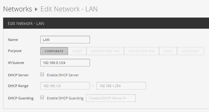
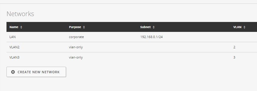
3. We pass in Settings -> Networks
We select the default network, edit, specify for example our corporate - 192.168.0.1/24
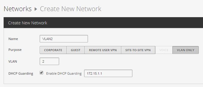
3.1 Creating VLAN2
Create New Network -> VLAN ONLY
We set the checkbox Enable DHCP Guarding and specify our DHCP server 172.15.1.1 for VLAN2
3.2 Creating VLAN3 - (all the same)
Create New Network -> VLAN ONLY
We set the checkbox Enable DHCP Guarding and specify our DHCP server 172.17.1.1 for VLAN3
We screw VLANy to SSID
We have reached the final moment of the trick - now we will attach our VLAN2, VLAN3 to the guest and corporate network
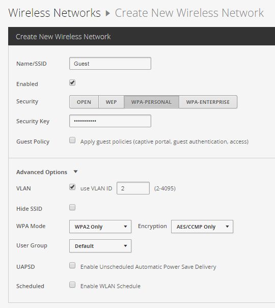
We pass in Settings -> Wireless Networks
Create a guest network with parameters:
Name / SSID: Guest
Security: WPA-PERSONAL
Security Key: password
Advanced Options ->
VLAN - Use VLAN ID 2
WPA Mode: WPA2 Only
Encryption: AES / CCMP Only
Usergroup: Default
Let's create a corporate network with parameters:
Name / SSID: Corp
Security: WPA-PERSONAL
Security Key: password
Advanced Options ->
VLAN - Use VLAN ID 3
WPA Mode: WPA2 Only
Encryption: AES / CCMP Only
Usergroup: Default
Results
At this, the basic configuration of the Ubiquiti UniFi Controller is completed, your access points now receive IP addresses from the 172.16.1.1/24 network, now the clients that connect to the Guest wireless network receive the IP addresses 172.15.1.1/24 and access the Internet under the external IP 100.100.100.102 , and clients who connect to the Corp network, go to the Internet under an external IP 100.100.100.103 and pick up 172.17.1.1/24. Your office employees go to the Internet under the external IP 100.100.100.101. We also banned guest access to all private networks except ours. You can also use the guest network without a password - this is optional. This topology may vary depending on your needs, for example, you can remove the redundant network 172.16.1.1/24 ... Have a good weekend!
PS If you find spelling errors - please email me at PM
Source: https://habr.com/ru/post/263431/
All Articles