Open design universal microcontroller module

After a brief acquaintance in the last article with the Kinetis microcontrollers from the Freescale company, I would like to present the design of the microcontroller module on these chips.
The module was created in response to the need for a multifunctional , embedded , reliable central control unit with a good supply of functionality, a large number of I / O lines and a variety of serial communication interfaces.
The module is distinguished by small dimensions, original architecture, convenient detachable connections of the board-to-board type, which provide a relatively small effort to remove the module even with a large number of contacts (over 200), specialization for use in control systems in hard real-time.
')
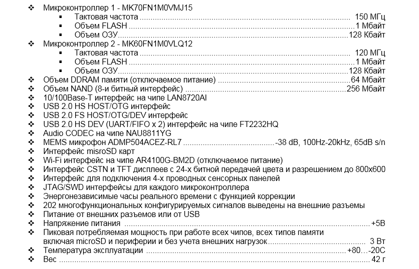
The module can be used in industrial devices and machines, for home automation , in robotics , for educational purposes to study microcontroller programming, in monitoring systems , and many other areas. Built-in Wi-Fi , Ethernet interfaces make it easy to integrate the module into global networks and the Internet of Things (IoT) . The built-in TFT display interface and fieldbus interface controllers help to make on the basis of the control panel module and logical programmable controllers. And the USB 2.0 HS interfaces and the built-in 8 independent 16-bit ADC channels with advanced programmable amplifiers make the module a good tool for recording and processing external signals on a PC.
The module contains two Kinetis microcontrollers on the ARM Cortex-M4 core from Freescale .
Why two microcontrollers and why Kinetis?
Here is a small analysis:
The market for embedded microcontroller modules today can distinguish the following trends:
- Modules on powerful chips class system on the crystal. These include boards such as BeagleBone, Raspberry Pi.
Their disadvantage is, firstly, in the very small number of available external input-output lines with functions of serial interfaces, multi-phase PWM modulators, DACs, etc. Secondly, such cards do not offer any software protection mechanisms. They are designed exclusively for public open projects. Thirdly, they cannot provide low-power modes comparable to the chips on the Cortex-M4 core. In conclusion, they are not designed to work in systems with a hard real time. Manufacturers position them mainly as platforms for general-purpose operating systems such as Linux, Windows. Attempts to work with these boards without operating systems often stumble upon the unavailability of complete documentation. - Modules on the simplest 8-bit microcontrollers, characterized by ultra-low price. This is the Arduino and its variations, and clones. Here is the problem in functionality and performance. It is solved by additional fees, as a rule, with its microcontrollers. But the functionality still leaves much to be desired. Debugging tools also limp. Low capabilities and development environment.
- Modules on FPGA. The processor core is either already built into FPGA or synthesized in it. In any case, the in-circuit debugging functions of the software and the analog functions are weaker than those in microcontrollers, power management is less flexible, and peripheral controllers have to be synthesized themselves. High-quality peripheral controllers, such as in Cortex-M4 chips, for UART, CAN, scatter / gather DMA, USB, Ethernet are expensive and must be purchased separately.
- Modules with single 32-bit microcontrollers from the families: STM32F, LPC, EFM32, etc. In general, these boards form such a mass of solutions where it is difficult not to find something suitable. But modern trends of increasing software complexity lead to difficulties in ensuring the reliability of its operation on a single chip. Reliability is traditionally provided by the use of two or more microcontrollers, and preferably by a network of microcontrollers on a chip or board scale. The middleware and application software is becoming too complicated even for coffee makers; getting it to work on a single chip more and more difficult.
Conclusion:
Two microcontrollers make it possible to isolate critical and non-critical parts of an application by dividing each part of them onto a separate chip. Add here the presence of a freely available operating system MQX , which supports the operation of multiprocessor systems. In turn, the core ARM Cortex-M4 incorporates a very effective means of in-circuit debugging, which become critical in the development of complex software. And since with the Freescale microcontrollers from the operating system MQX does not require a license purchase, the choice fell on the Kinetis family.
Technical characteristics of the module:
Structural scheme:
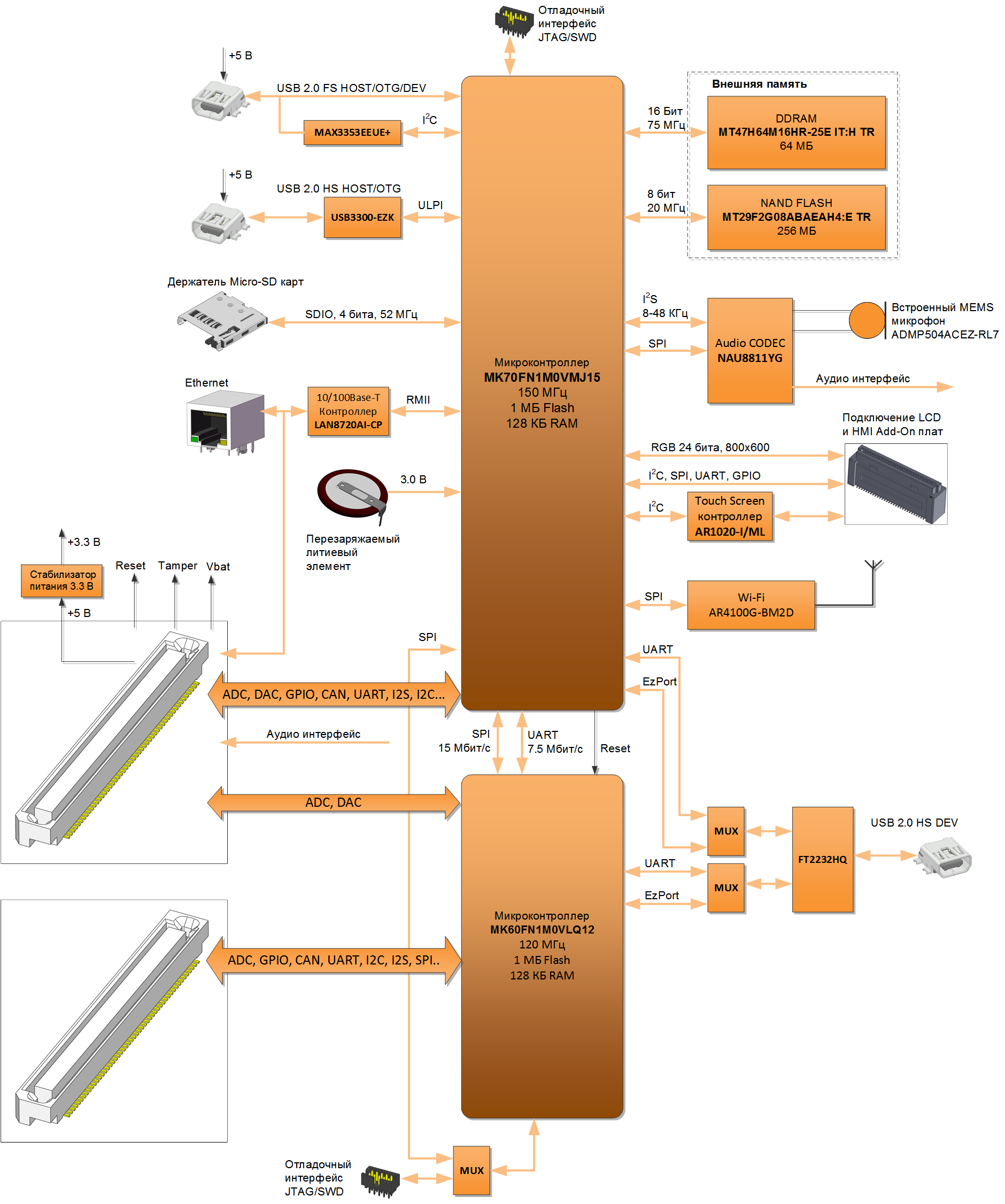
A feature of the circuit is the ability to simultaneously and simultaneously reprogram both chips on the board through a single USB HS interface, without using resident loaders. Those. even failures in the flash memory area of the loaders in the chips will not lead to the need to use special equipment to restore the module to work.
Also, one microcontroller (MK70) on the board can reprogram another (MK60) again without using resident loaders on the second. Both chips have the ability to protect software from being read.
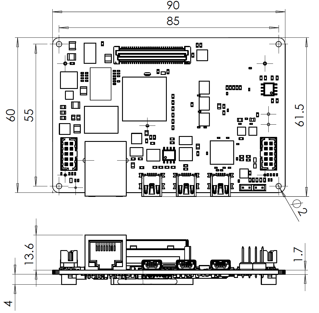
Module dimensions:
Pinout connectors:

Signals with suffix _2 belong to microcontroller 2 (MK60FN1M0VLQ12)
Unlike some similar modules, the signals output to the external connectors are not multiplexed with the peripherals located on the board and can be used without restrictions.
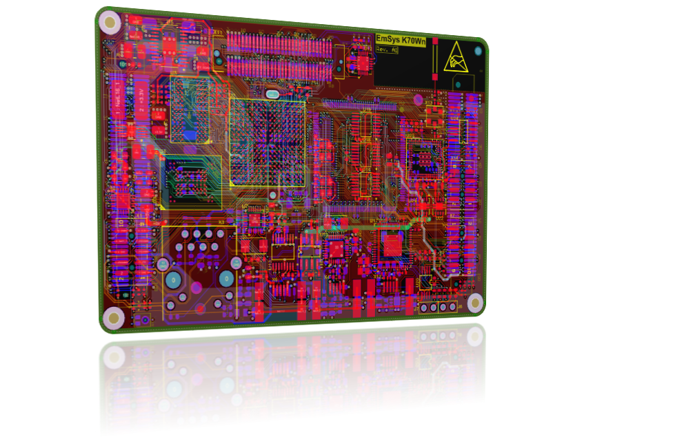
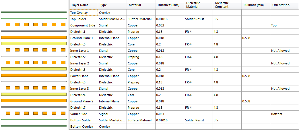
Printed circuit board:
The module board contains 8 layers of metallization, two of which are filled with earth and one is filled with 3.3 V. There is no fill under the Wi-Fi antenna. An omnidirectional antenna ANT8010LL04R2400A with a peak gain of 5.46 dBi was used.
Layer stack structure
At the moment, an additional board has been developed for the module with a 3.5 ”TFT display of 320x240 pixels and a touch screen.
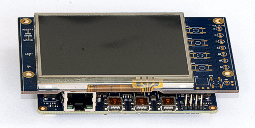
Projects of additional fees will be published later.
Complete source files for the production of the module board and the schema are here: https://github.com/Indemsys/EmSys-K70Wn-PCB
Source: https://habr.com/ru/post/262657/
All Articles