Shine always, shine everywhere. Start
Probably, this is a mental disorder - the desire to realize something of its own, whatever it takes, preferably from scratch. Especially nice to pre-shatter to the ground made by predecessors. The irrepressible desire to build your own bike is also explained by the fact that all existing solutions currently have fatal flaws - too few wheels, too many pedals, it is inconvenient to steer when landing backwards and so on. Here a wild fantasy turns on, and after a while the world community is overjoyed by a fundamentally new means of transport, exclusively adapted for two reptiloids and one raccoon.
This is me actually to the fact that I always wanted to build my home automation system. Connect a bunch of sensors and actuators, set up the work logic that I need directly, and enjoy the long catch of interesting bugs. Of course, you can use ready-made solutions. Now there are many interesting devices on the market for “smart home”, and if you approach the question in a monumental way, why not build a system based on industrial PLCs and I / O modules? To bring all this stuff into a SCADA system ... Pretty tempting. But the creative itch does not allow us to take advantage of the many years of experience of hundreds and thousands of other people, this is how capoeira begins on a rake.
')
I still have a little common sense. In addition, from the cabinets and from the shelves at me, periodically with mute reproach, I look at the unfinished devices, to which I have to get "someday." So, we need to set ourselves a relatively real task, the solution of which can be brought to its logical conclusion. Let's start with the lighting control in a small city apartment.
I am repelled by the following theses:
1) Overhaul. In terms of power and low current wiring, the hands are completely untied.
2) The ridge of the system - only wired. I do not rely on Wi-Fi or 433 MHz in critical areas.
3) Minimal use of ready-made devices and units. For self-education, pumping development skills, installation, programming.
Now concretized.
1) The main lighting - LED strip. Bulbs are sent to the dustbin of history. Additional lighting - fluorescent lamps. This is for the birds. Their vision is considerably different from ours, therefore, in order to be comfortable and comfortable, they use full-spectrum lamps with a certain amount of ultraviolet radiation.
2) On-off (for all lighting fixtures) and brightness adjustment (for tapes) should be carried out both manually and programmatically.
3) For emergency situations, an “iron” bypass of the system is necessary. Roughly speaking, the "brains" were cut off - go on manual control.
Now I focus on the second paragraph. The following tasks are highlighted here:
1) Formation of the list of executive devices. Just two. Driver LED strip and "relay". In quotes - because in fact it is a triac.
2) List of control devices. Too two. A knob with a button and just a button.
3) Select the method of communication. You need to dwell on it.
Since I decided that the wires will be used, there are few options. Ethernet can be used. One network, all on TCP / IP. It is tempting. But when I imagined a microcontroller with an Ethernet and a single button, I felt a little sad. We go further, in the direction of reducing the number of wires and minimizing the requirements for iron. The complete solution is DMX512. At the low RS-485 level, everything is fairly simple to implement, but there is no feedback. What else? CAN? Good industrial option, but I want it even easier. Modbus over RS-485? Already warmer. But what about cycling? In addition, I have already tuned in to the use of cheap microcontrollers with minimal strapping. And here it is, the decision. I’ll take RS-485 and think up my own ersatz protocol for it. In this case, however, it is necessary to leave the path to retreat. If I dig in, I'll come back to Modbus again.
So, the RS-485 network, the master computer (the malinka, most likely), all other devices are slaves. In terms of iron - ATmega328 + MAX485. The controller is exactly this because of the presence of several things, with a successful scenario in the "serial" device is replaced by ATmega8. The packet consists of five bytes. Device address, command code, two data registers and checksum. The master sends the packet, all the slaves accept and parse it. If the address is the same and the checksum is correct, certain actions are performed and a confirmation is sent. In my opinion, nowhere is easier.
I decided to take the matter "from the middle". Power wiring and any protection devices are later, because everything is relatively clear here. But in the design and debugging of new devices for me there will be a lot of fun discoveries, so I start with iron. Or rather - with two devices, the regulator and the driver of the LED tape.
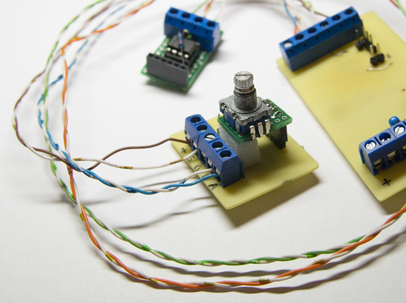
Regulator

Mechanical encoder with a button, microcontroller, RS-485 adapter. First I implement the connection, then the actual processing of the encoder. Communication works as follows:
1) When the device is turned on, the register values are set to 0. Later they will be loaded from the EEPROM. The address is clogged in the code and will also be stored in non-volatile memory in the future (there is a cap for the procedure for changing the address).
2) During the initialization process, the modes of operation of the UART and the timer are configured (used to stop receiving on timeout)
3) On the ~ RE and DE pins of the MAX485 adapter connected together, the low level is the receive mode.
4) Waiting for reception of the first packet. As we waited, we start the timer and take four more bytes.
5) If successful, the reception of the five-byte packet and the correct checksum (it is really just a sum, not a CRC) the packet can be parsed.
6) If the address in the packet matches the device address, we check the command code (the second byte of the packet), depending on it, perform the required actions (for example, write the variable values of the third and fourth byte). Within the framework of the described system, I call these variables the device registers.
7) We send confirmation: ~ RE and DE high level, transmission resolution, sending a packet (with the address of the master, some command code and the current value of the device registers).
8) GOTO 3
The receive timeout is monitored simply: the timeout flag is initially 0. When the timer is interrupted, it is set to 1. This flag is checked in the wait cycle for four bytes of the packet.
Now encoder processing. Principle I learned from here .
In short - we keep the current state of the encoder, by interrupting the timer we read the new one. Depending on what has changed - we determine where the pen turned and whether the button was pressed. So, in paragraph 2 of the above list, the initialization of Timer2 is added with the expectation that the interrupt will occur at about 1 kHz. Plus, in order not to interfere with the operation of the UART, in the process of reading or writing to 0, the enable flag of polling the encoder is set (checked in the interrupt handler of the second timer).
Actually, the regulator does not need to know anything else.

I do not describe the errors in the layout and other minor troubles. To wash the board is also no good at all - she will still get a couple of pokes with a soldering iron
About rake at this stage
I only had one trouble with the encoder. She was generally associated with all devices. Periodically, the network had an extra zero byte, which badly spoiled the picture. Given the absence of an oscilloscope and a logic analyzer, the problem had to be looked for theoretically. It turned out to be enough to pull the TX to Vcc so that when switching the "receive-transmit" no unnecessary processes occur.
Driver

We have already solved the communication problem. We take what concerns RS-485 from the implementation of the controller and add PWM to one output by means of Timer2. The first register of the device is responsible for the brightness, the second for switching the output on and off as such. In terms of iron, I use the already proven scheme of two bipolar transistors (they used to be BC639 and BC640, now I use SMD BCP53 and BCP56), the output is IRF540. There were no interesting jokes with the driver, except for such a buggy 12-volt power supply, whose operation caused the entire system to freeze at once.
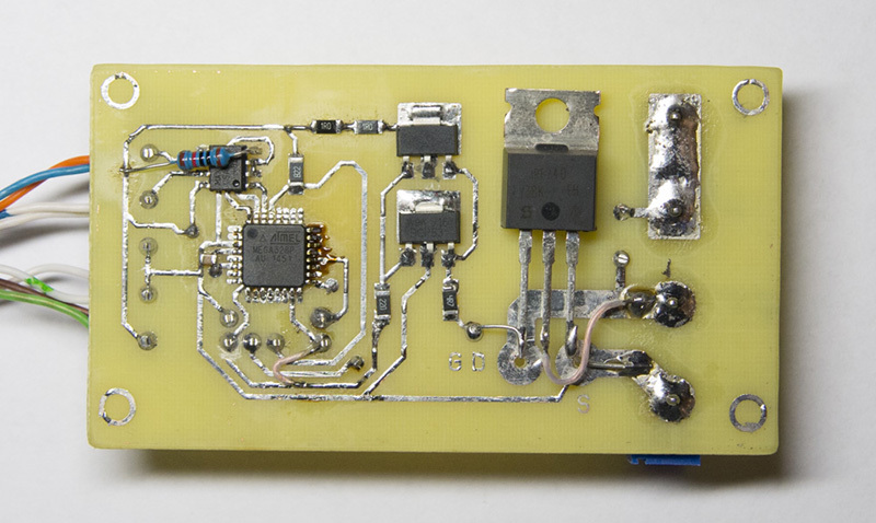
There is also a lot of mounting ugliness. An early prototype that is already there.
General notes on hardware
Microcontrollers are clocked at 8 MHz without external quartz. The power harness consists of a single 100 nF capacitor. Conclusion ~ RST pulled to power through a 10 kΩ resistor. I have already mentioned that the stability of the work has drastically improved after tightening the TX to the power line. When constructing a regulator, I did not rely on internal pull-up resistors (on the pins to which the encoder is connected), but used external ones. No more tweaks (yet?) Required. The RS-485 line is pulled to Vcc (A) and GND (B) through 560 ohm resistors from the lead adapter, terminated at both ends with 120 ohm resistors.
The project is available on github , the structure is as follows:
- avr-dimmer - driver firmware (project Eclipse + AVR);
- avr-encoder - regulator firmware;
- host - network wizard software (Python), about it next time;
- At the root are the schemes (Eagle) and PCB layout (Sprint Layout 6).
Next time I will talk about what is happening on the host side (network wizard).
UPD. 2015-07-19 the second part , in the gland, too, there are changes.
Source: https://habr.com/ru/post/262633/
All Articles