My system for testing and improving the quality of a GSM gateway, part one: functional and circuit level
The second part of
How it all began
I work in a small company that develops and produces systems for recording telephone conversations. But in some cases, customers need an analog GSM gateway as the source of the telephone line. Previously, it was purchased and resold. But what they bought was of poor quality and the marriage often came across - it was decided to develop it themselves. We have developed together: a circuit designer and I am a programmer, recent graduates without development experience in analog telephony and no implementation experience in production. It turned out, to put it mildly, not very, although the problem of marriage was solved and rather “contrary to”.
But the problem is that for us, even 1% of the marriage is unacceptable: for each case, those support and developers took a lot of time for the client. And for all of us this is unacceptable purely for reasons of professional pride. We wanted to take such a gateway out of production, even though we had a share of each product. It is very embarrassing when dealers about other products say: “Do you have a marriage at all?”, And about our “we are afraid to sell them, they will not buy anything from us later”.
')
All this became a royal kick to the complete reworking of the gateway, a detailed study of the quality and development of a testing system. What I did, and what further and tell you.
How are we from this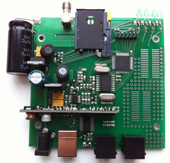
From the bottom of the board only the Chinese GSM module
From the bottom of the board only the Chinese GSM module
Come to this
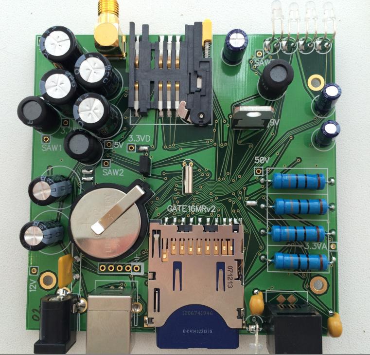
Top:
Bottom:

Bottom:
I'll tell you how the product has completely changed and a system of testing and production support has appeared. I'll tell you how the functional diagram has changed, explain how the electrical circuit of the modified version works. And in the following parts I will tell you about the logs and testing algorithms and how the board is tested. I will give a little source code. And I will tell about the distributed automated workplace for a firmware, testing and the analysis of logs that was developed on production and at developers.
The first version of the gateway: analysis of errors
Allowed to reduce the number of marriages every ten. And as a simple gateway, it basically works fine.
But due to inexperience, three significant mistakes were made:
The first mistake: we produce recording systems and everything is just waiting for them, but they were not in the gateway. Dealers and customers were disappointed.
The second error: ready-made low-quality modules were used, the Chinese GSM module was buggy, and the telephone interface was sensitive to any non-standard use - it burned. Moreover, non-standard use is not a connection to 220V, but the one to which users and communications workers are accustomed to and is considered the norm. For example, the connection to the PBX port is not intended for this: when the line source was connected to the source on the PBX.
The third mistake: the overall structure is too simple, everything is done right next to it: there are no settings, even the volume and there is no stock for the firmware - it takes 99.9% of free RAM and flash. Everything is connected directly, and not through the microcontroller. In fact, it is not possible to refine both programmatically and circuit-wise. The possibility of updating the firmware is also not.
There was no provision for any production testing - just to check that it just works - to call and check that you phoned, there is a sound in both directions and the number is issued. There was practically no interaction with production, we and they lived separately. We did not try to collect and sort out what we have developed. And did not even think how it will do.
Three months is a short period of testing, the main stream of complaints was after the first year of sales, some customers who bought the gateway many years ago, are still only now beginning to use it and ask questions.
Now many problems have been fixed: the protection was set, and the Chinese have improved the quality of GSM module firmware, but the sediment has remained. But the settings were both absent and absent, which is very inconvenient for many: the sound in the gateway turned out to be louder and clearer than most Chinese, but for some customers it is too loud. And what to hide - I’m on the line - hence the 99% flash usage and it’s impossible to fix or add anything in this pasta wretchedness.
Option Two: Work on the bugs
It was decided to completely redo everything from the organizational level to the functional and microcontroller choice. It was necessary to make not only the device and its firmware, but also to do production testing and completely think through the interaction with the production from scratch. Such a system so that you can log all the parameters of the product and the production process. And so that it was not an empty bureaucracy, but a convenient tool that helps keep everything under control and look for the cause of marriages and failures. You also need to make such circuitry and firmware so that you can manage all parameters and be able to track any parameter from any gateway, and notice that it began to deviate from the norm of such and such number when you bought such and such a batch of components.
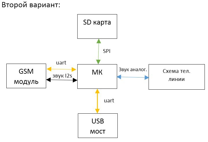
We decided to make everything possible on the microcontroller programmatically : the MC should work in a gap, process both the sound and control the telephone line with the GSM module. Fully implement on MK sound processing and telephone line, and make it so that it can not be burned even plugging in 220 or stun. The first option was on AVR atmega8512, and it somehow was enough to generate a beep and caller ID. They decided to do the second option on the ARM-Cortex M3, and later on the ARM-Cortex M4 - it was necessary to implement echo cancellation themselves. And this is a very difficult computational task of finding a global minimum in a 256-dimensional space in real-time. In the MK there should be a stock of RAM, flush and boot process, at least 50%. It must be possible to update the firmware of the client.
There were three people in the development team - a new employee was hired. He was instructed to do the main firmware, immediately agreeing that he takes care of all the work with customer support - so that he does everything at once perfectly. No “at the beginning we will roll out IT, and then we will test on users” - we have already tested it, did not like it. And since I had experience with marriage and I knew better circuitry at that time, then I took upon myself the development of a test firmware and a quality system. This allowed us to make two independent firmware, combat and test firmware, and to look at the circuitry from two independent points of view, comparing what they wanted and what they got in the circuitry. And also control each other. I did some of the work on the main firmware, and I checked, as well as taught the beginner, since he was without work experience he had to learn a lot on his own.
It was decided to collect and sort out the first batch of gateways themselves, so that they themselves could see their mistakes in technology. Production was surveyed and their wishes were taken into account. Later, I collected not only circuit design fees, but I also made a small batch, while the circuitry engineer was on vacation. And also they themselves debunked several batches of 10 ... 40 pieces, which made it possible to debug test software and interaction with production.
We decided to do it on a four-layer board - this was required by both the MK and GSM module and less analog noise when separate layers are allocated for the “ground” and power supply - their resistance is substantially less. And the GSM module is very noisy - it consumes in pulses of 2 Amperes, the frequency of the pulses as if overwhelming the broadband spectrum for the entire audible range.
The GSM module was taken without a Chinese bydlokod inside - an Italian design, but a Chinese one. Its internal firmware was an order of magnitude more thoughtful and quality. We chose a model such that the sound was immediately digital, so as not to catch analog interference at the interface between the MK and the module and reduce the number of analog circuits to a minimum.
The gateway must be able to verify itself , including the telephone jack and the presence of the telephone. This will allow to conduct self-diagnostics directly at the client at once considerably simplifying technical support. In order for him to be able to check himself, he had to add a telephone simulator inside the gateway - so that he could pick up the phone and answer calls. And also added measuring circuits of key parameters, such as: power supply current, voltage, power supply capacity - for example, to check that the conduits were not swollen.
The gateway was convenient to configure: they made a voice menu that pronounces everything: settings, their values, allowable values, how you can change the volume, speed dial, and so on. For this, Speex sound decode was used.
The gateway should be able to record conversations . Finally, the fact that everyone was waiting for us. Write to a full-size SD card - the device is large and there is no point in crushing. Moreover, microSD has more consumption and does not always support SPI. Records are added to the card in 3 compression options: pcm, a-law, adpcm. Log entries are also conducted in the html list with the ability to sort (in javascript) by any column.
It was:

It became:
Circuitry
We put 0805 resistors with an accuracy of 1% instead of the usual 5% - this will allow us to conduct tests more accurately and get more information. This is necessary, for example, in order to see a small tantalum capacitor in 330 microfarads, against the background of very large electrolytes connected in parallel in the range of 5,000 - 10,000 microfarads, and they filter different frequency ranges of sound. Similarly, capacitors 0805 with an accuracy of 10%. More accurate components allow you to avoid adjusting the firmware settings. At the same time, the difference in cost when switching to more accurate components against the background of the total cost is scanty.
Simplified electrical circuit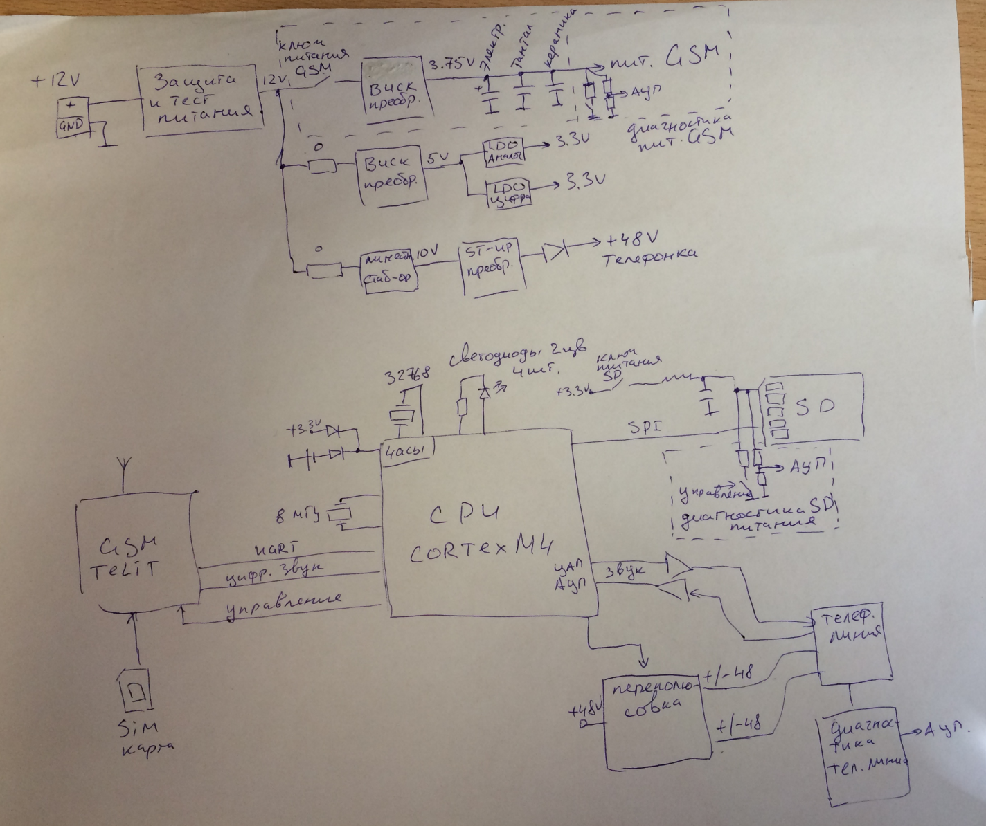
Sorry for the hand-made, but there is no strength to fight with the new office
Sorry for the hand-made, but there is no strength to fight with the new office
Supply system
The gateway is powered by a purchased 12 volt 1A stabilized power supply from 220V.
Whole Food Scheme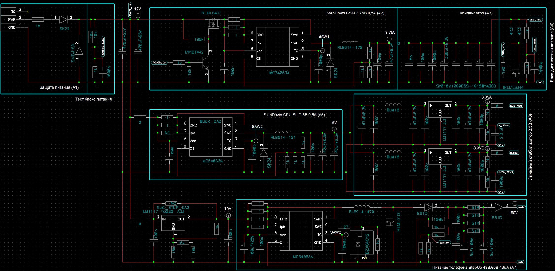
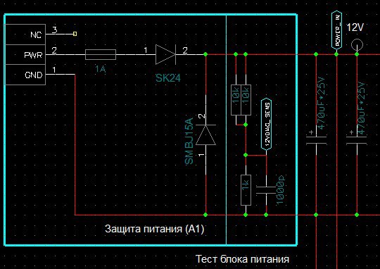
Immediately after the power connector is the power protection circuit, protection against reverse polarity - the usual schock diode. Current fuse in 1A. And an overvoltage suppressor with a 15V threshold. Next comes the supply voltage measurement circuit with a 1: 6 divider on the resistors. They will check the power supply, the load given by turning on and off all consumers (about 0.7A).
After the protection and measurement scheme, the power is divided into three branches: GSM, telephone line, digital-analog power.
For all three we use the pulse stabilizer chip MC34063A. She knows how to raise and lower the voltage. Also has current and temperature protection. Voltage and current can be set by resistors. Its advantages in price and ease of use, and also in efficiency, it stabilizes better with greater efficiency than linear stabilizers - it heats up less. But it makes noise and after it it is necessary to put filters.

For convenience of power debugging, checkpoints and solder jumpers are installed on all branches, which connect the load to the power supply. Assembly is made without jumpers. The installer immediately connects to the power supply and checks all the power lines at the control points. Only after the voltage has been checked, the jumpers are sealed. And then the test firmware is already running out.
GSM power branch

For a reliable reset of the GSM module, you must be able to control the GSM power supply - for this, at the very beginning of the branch there is a key on the field effect transistor. Next, a stabilizer of 3.75 V and 0.5 A. The GSM module consumes 500 microns in pulses during operation. sec x 2A, and this is very much and it is they who usually lead to sound pickup and therefore they need to be filtered out. For this purpose, electrolytic capacitors with low internal resistance are supplied, 4 pcs to reduce it even more. And there are tantalum and ceramic capacitors - they all filter at higher and higher frequencies. A stabilizer also contributes to filtering - it limits consumption pulses from 2 A to 0.5 A, does not allow taking all 2A from the power supply, these pulses are taken from the capacitors, thus reducing the effect on other power lines.
Next comes the power testing circuit - a power sensor and a test load of 2.15 Ohms, controlled from the MC via a field device, using it you can measure all the main power parameters: voltage, current, load resistance.
A branch of digital and analog power
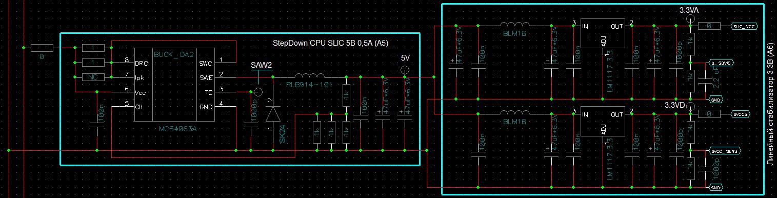
The food is divided into two sub-branches:
- Analogue power for op-amp output and reception of sound from the line, and for the DAC and ADC in the MC.
- Digital power for the MK and SD card, they also consume pulses, especially when recording sector on the SD card.
If you do not separate the analogue from the digit, then the client will hear the conversation when the SD card works and wakes up / falls asleep to the MC. The power is stabilized in two stages, at the beginning it is lowered by a puller with good efficiency up to 5V, but it is noisy, therefore it is further stabilized to 3.3 by two quiet linear stabilizers. And if you immediately put two linear, then they will be very hot because 9B will fall on them. Also, each sub-branch has voltage meter circuits on 1: 2 dividers.
Power line power supply
The telephone line is a 48V / 60V voltage source with an internal resistance of about 700 ohms.
During the call, the voltage should be 60 V and change the polarity 20-30 times per second, the rest of the time 48 V with constant polarity.
The rise of the tube is detected by the fact that the phone loads the source and, due to the internal resistance of 700 Ohms at the connector, the voltage drops to about 10 V, at a current of about 30-40 mA.
But power = power_current * voltage, and when the tube is lifted, the internal resistance drops 38V at 40mA. And this is a lot of heat. So much so that the gateway would have to do the size of an A4 sheet. It is expensive and inconvenient for customers. Therefore, we acted slyly: we made it so that when the tube was lifted, the source ceased to stabilize the voltage, and began to stabilize the current. The current remains the same, and the voltage is already 2 times less than the voltage. Less heat.
But here a problem arises - when the current is limited, the stabilizer no longer stabilizes the voltage, and all voltage disturbances directly pass through it. But the sound is given in the telephone line by modulation of 1V of the telephone voltage of 48V or 10V if the handset is lifted, i.e. interference is amplified from 10 to 50 times.

To solve this problem, at the very beginning we put the LM1117 linear stabilizer on 10V. And then after it is a pulse stabilizer MC34063A, which stabilizes either the voltage or the current if the tube is lifted using an already stable power supply. In order for the stabilizer to increase both to 48V and to 60V, a variable was made in the feedback circuit: the connection of the MK leg is indicated by a red arrow, with which it shunts the resistors in the feedback (connecting to the ground), and the stabilized voltage rises to bell , the rest of the time there is Z standing. But the impulse is noisy, so the next is a first-order P-filter on an RC circuit of 5µF and 4x51 Ohms. As well as an E1SD diode, the purpose of which is to protect against currents flowing into the circuit (for example, when connecting 220V or other interference).
Telephone line source
Whole scheme
On the left there is a telephone jack, to the right is protection in the form of a 85V suppressor and a pair of self-resetting fuses for 80mA, in parallel with them a spark gap is connected in the form of two bare pads.
It looks like this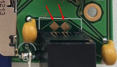
This protection well protects the power supply from 220V and from spark interference during a thunderstorm. But its speed is not high enough and quick splashes can pass through to the sound, therefore, to protect against them, all the output and reception op-amp inputs are protected by additional Schottky pair diodes BAT54S that protect against voltage above the power supply and below the ground.

This is a test tube lifting circuit, with the help of its gateway it can check itself and pick up the tube itself. The load is selected at 1kOhm because it is convenient - a 1V drop is 1mA of current.
The line of receiving sound from the line:

Made at the OS in differential switching - in such switching on, the own noise relative to the telephone line is subtracted and not heard. Only the difference between the contacts in the telephone jack is heard. To receive only the sound at the input are capacitors, a few pieces because they are 50V, and the sound can have a larger swing (when calling). The output of the shelter is an RC low-frequency filter.
The line of sound in line:

Sound must be supplied to the telephone line with current, therefore, a current source is assembled at the OS. At the input of the op-amp is an RC low-pass filter. OU itself on three resistors 27 ohm maintains the voltage the same as at the input after the RC filter, thereby setting the current.
OU feedback is protected.
By issuing a sound to the line, you can check and receive the sound from the line by issuing and listening to the result, which is used in the test firmware. It also checks the frequency response.
AFC of the real gateway and its description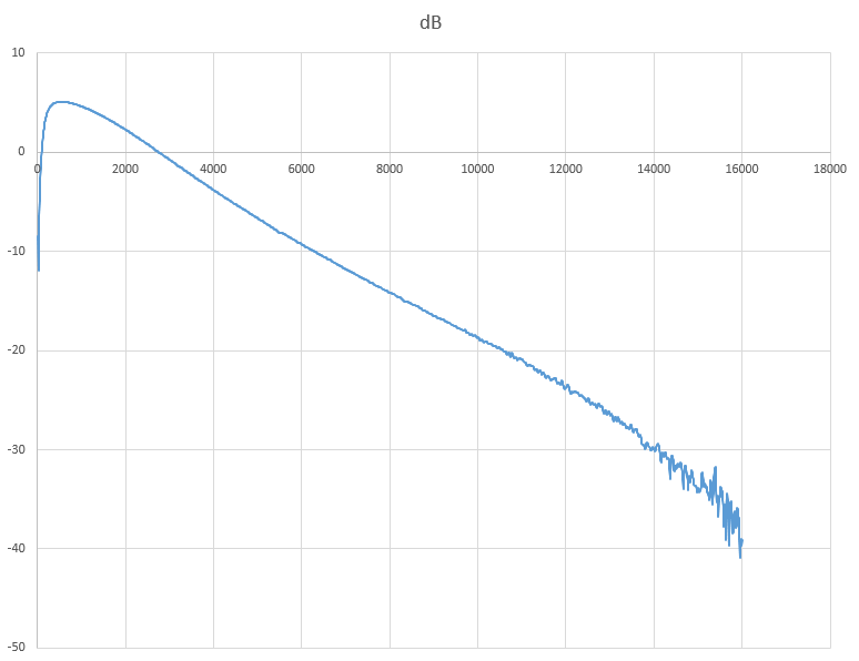
By X - Hertz, by Y - decibels.
At the lower frequencies there is a decrease due to input conders that separate the sound from the constant component.
On medium and high decay due to RC-filters on the output and reception of sound from the line - the RC-parameters of filters are measured by this decay.
Polarity reversal pattern:
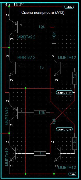
Conventional H-bridge allows you to change the polarity of the telephone line. Made from complementary pairs of transistors.
Diagram of telephone line internal resistance:


Made on large resistors, they can not be burned - the tracks burn more quickly, they have large parasitic inductances and resistances - they filter noise well. They also dissipate heat well. And paired with an RC filter on a 0.33 conductor and 51 ohm resistors, they filter the sound well from interferences, including noise from a booster.
Behind these huge resistors, the rest of the circuit is like a stone wall. The rest of the telephone line source implementations that I saw were made without such resistors and were burning because of this. Including our first version of the gateway.
USB bridge layout

Chip CP2103 is used. It is used both for communication and for flashing or resetting.
It is convenient because in addition to the RS232 handshake lines, there are GPIO - input / output legs. The problem is that when connected to a PC, the OS starts pulling acknowledgment lines, and the GPIO does not touch it, and if the MC reset buttons are connected to them, the gateway will be reset and the conversation will be interrupted. Therefore, resetting and switching to the integrated bootloader mode is connected to the GPIO. And with the help of only this bridge, the gateway is flashed both at the production site and at the customers if it is necessary to update the firmware.
GSM module circuit
Scheme
Used 2.5G dual-band Telit 868 dual module. Those. It will work only in the CIS countries. The SIM card holder is a regular tray.
Digital DVI sound (renamed I2S).
Microcontroller circuit
Scheme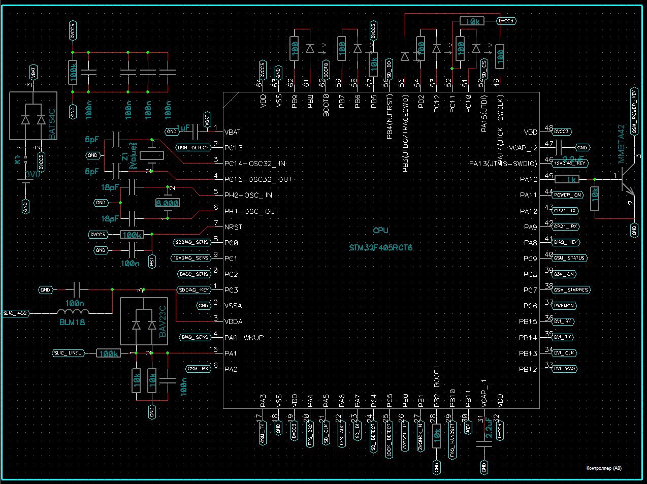
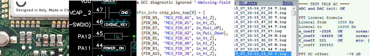
Used micron STM32F405RG with
168k of RAM and 1024k Flush, is used by 50%.
160 MHz clock frequency is used at 3/4, the main consumers are speex decode and echo cancellation
MK has a temperature sensor - it is convenient to monitor the device self-heating.
Also in MK there is an internal reference voltage, they can measure the reference voltage of the ADC and the supply voltage - in this way, the mic can check itself and its power supply. And thus make sure that he measures everything else correctly.
Provides power from a lithium battery - tablets for storing dates and times. Is able to request them from the GSM network.
Status indication on four red-green LEDs.
SD card
Scheme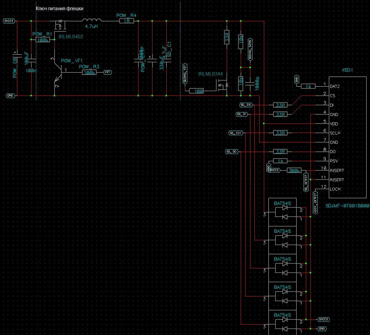
On the left you can see the on and off key, after it there are capacitors including tantalum at 330 microfarad, without it the SD card will be unstable, because when writing and erasing large blocks of data, it can consume a lot of current per pulse.
Further, the key is for testing the power supply by connecting a test load, as well as a supply voltage meter on the 1: 2 divider on the resistors. The key for testing is also important in the main firmware - they can discharge the power to zero volts, if this is not done, the SD card starts to be very buggy with the next power up.
Bottom visible dual diodes protect the SD card during a hot connection.
On the right of the diagram is a card holder with push-pull mechanics - inserted-snapped in, pressed-snapped-out.
On this with all circuitry.
The board of both options was divorced in the program TOPOR.
Continued in the next two articles. In the second, I will tell you about the test firmware, how it works, which measuring complex with a frequency analyzer, etc. I did in this firmware. In the third I will tell about the distributed automated workplace, about my server, about the loader and about the interaction with the production.
Thank you so much for your time. I hope it was not boring.
Source: https://habr.com/ru/post/262531/
All Articles